Week 10 - Challenge 3 - Door Trim Lower with Engineering Features
----------------------------------------DOOR TRIM Lower with Engineering Features ---------------------------------------
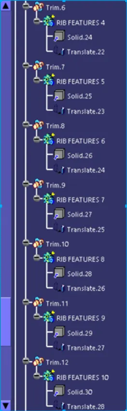
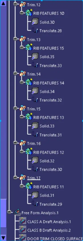
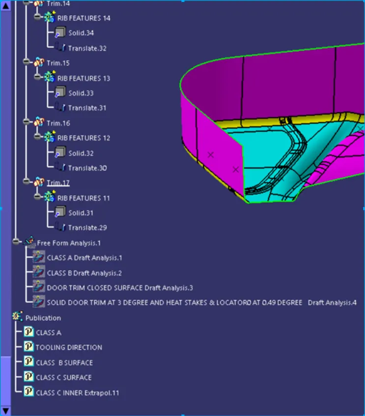
- TREE STRUCTURE
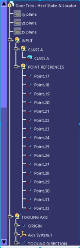
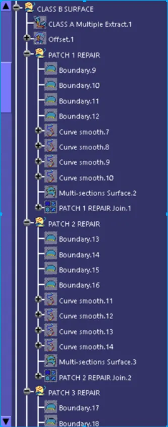
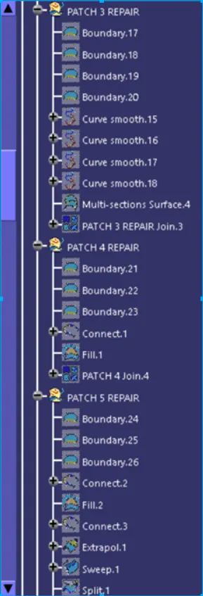
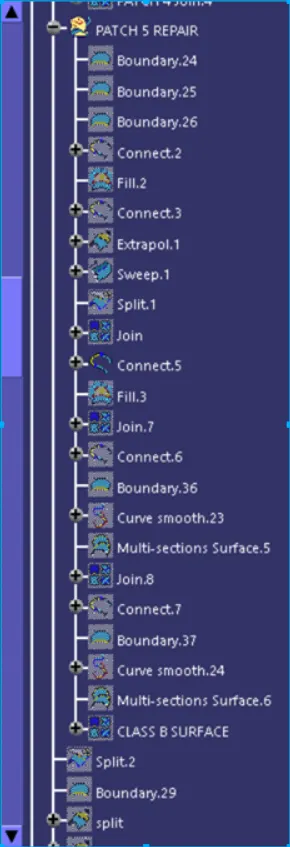
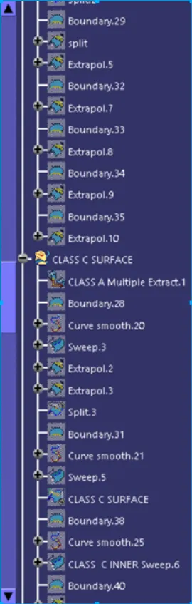
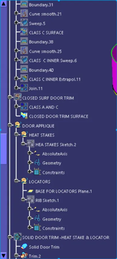
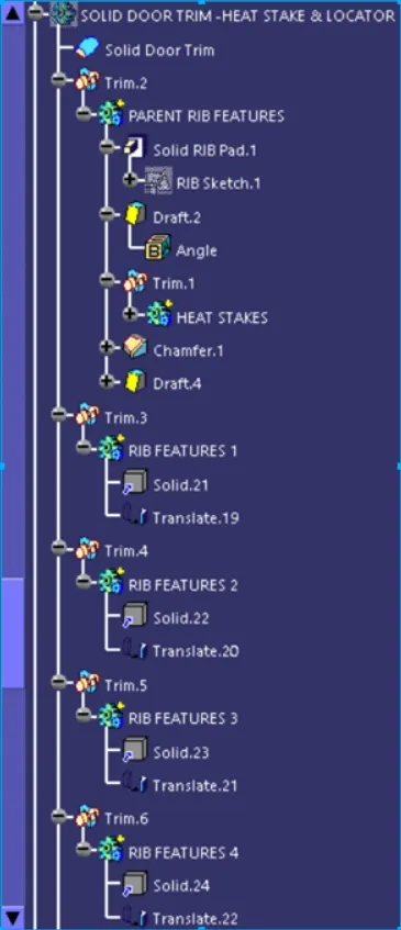
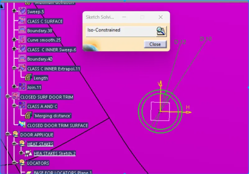
- SKETCHES
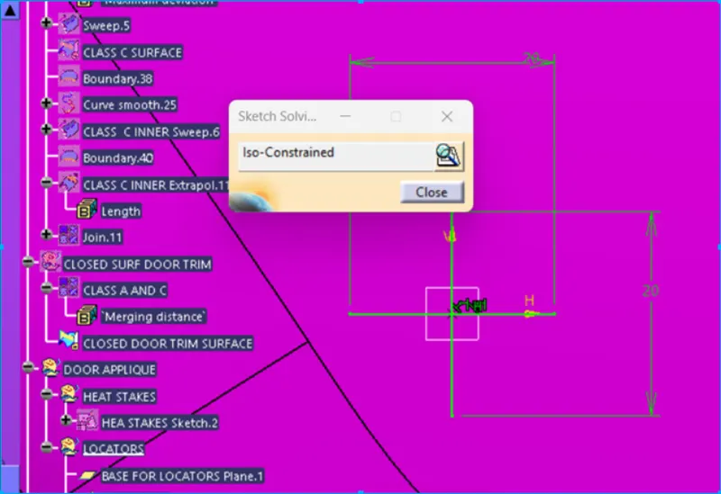
1. CREATION OF TOOLING AXIS
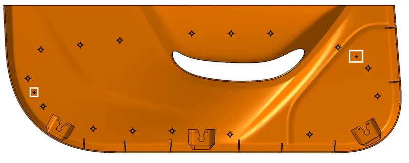
- Create a point on the CLASS A surface which is showing in below image.
- Insert axis-system at origin point.
- Create line with point and direction method in which point will origin and direction will be Y-axis.
- Now this line will be tooling axis,So for prooving this line we will test draft analysis on CLASS A surface.
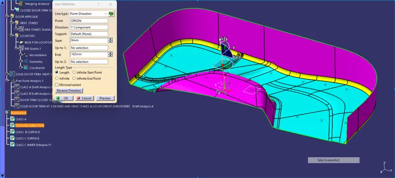
2. PERFORMING DRAFT ANALYSIS ON CLASS A SURFACE AND FINAL COMPONENT
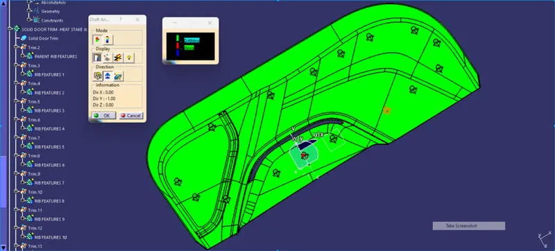
Draft analysis on class A surface with 3 degree draft
Our Tooling Axis creation is correct
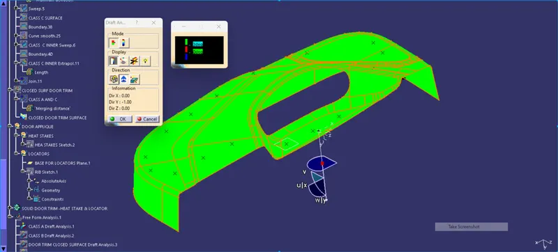
Draft analysis on Final component with 3 degree draft
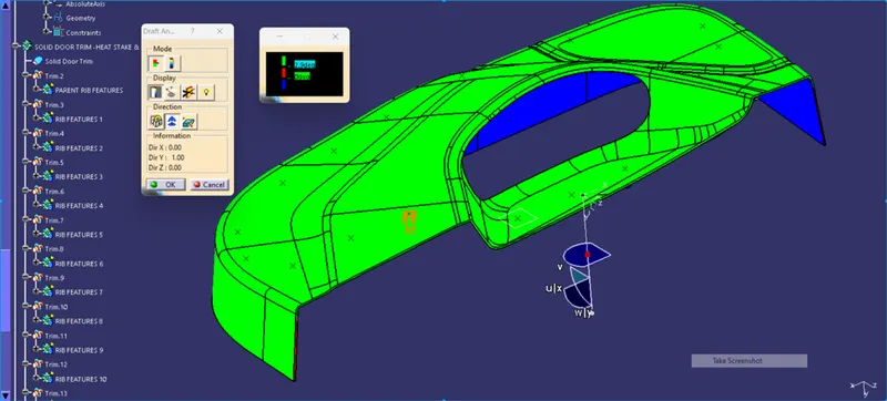
Draft analysis on Heat-Stakes with Locators at 0.45 degree draft
3. CREATION OF CLASS B AND CLASS C SURFACE
class B surface is taken offset of 2.5mm from class A surface to inside. Then some patches was repaired by fill or multisection command.
Class C surface is taken at 3 degree draft angle with reference surface and from tooling axis.
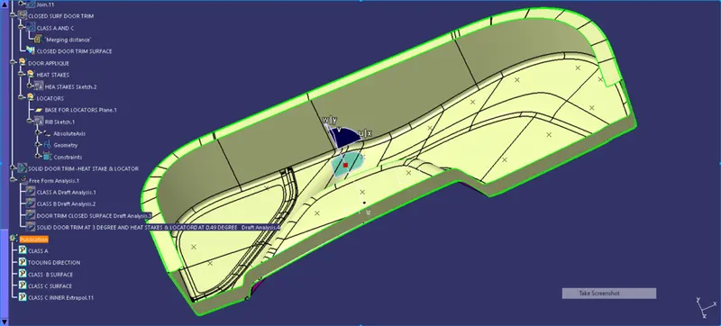
4. Heat stake and locators to the Door Applique trims
In the given Class A surface approx 16 points is given for positioning the Heat stakes with locator. So now i have to make single Heat stakes with locator then copy to all positions.
- Create sketch for locator which will same as the rib (cross sketch).
- Solid extrude according to rule of rib height (H < 5x nominal wall thickness, wall thickness = 40% of nominal wall thickness) and extend in opposite direction also(approx 4mm).
- solid draft of 0.5 degree per side on locators wall.
- Now, sketch of two circle at the same position of locators in which the outer circle is 2mm more than inner dia which means thethickness of heat stakes will be 1 mm.
- solid extrude approx 25 mm height.
- Apply the solid draft of 0.5 degree outside and inside of heatstakes.
- Use the Solid trim command and apply on locators with heatstakes in which the useless extension of locators inside of heatstakes will remove and then heat stakes and locator will be Union part. Now it is ready to Distribute at all points position.
- Copy parent heatstake & locator union part translate the all designation place.
- Now use the Union trim to join the Heatstake union part with the main door trim , because some extended length of heatstakes union parts is penitrating the class A surface.
- Now Whole Union component is ready to manufacture.
5. DETAIL REPORT BASED ON DRAFT ANALYSIS RESULT
- SCREENSHOT OF SOLID DOOR TRIM IN VARIOUS ORIENTATIONS
FRONT VIEW
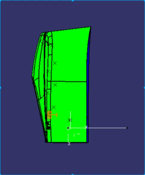
SIDE VIEW
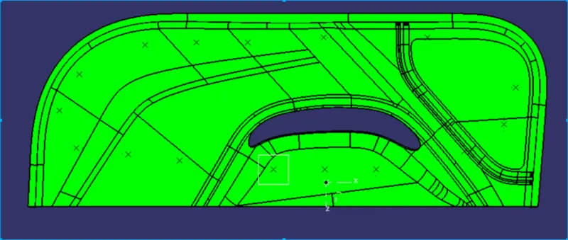
TOP VIEW
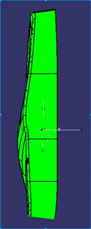
ISOMETRIC VIEW
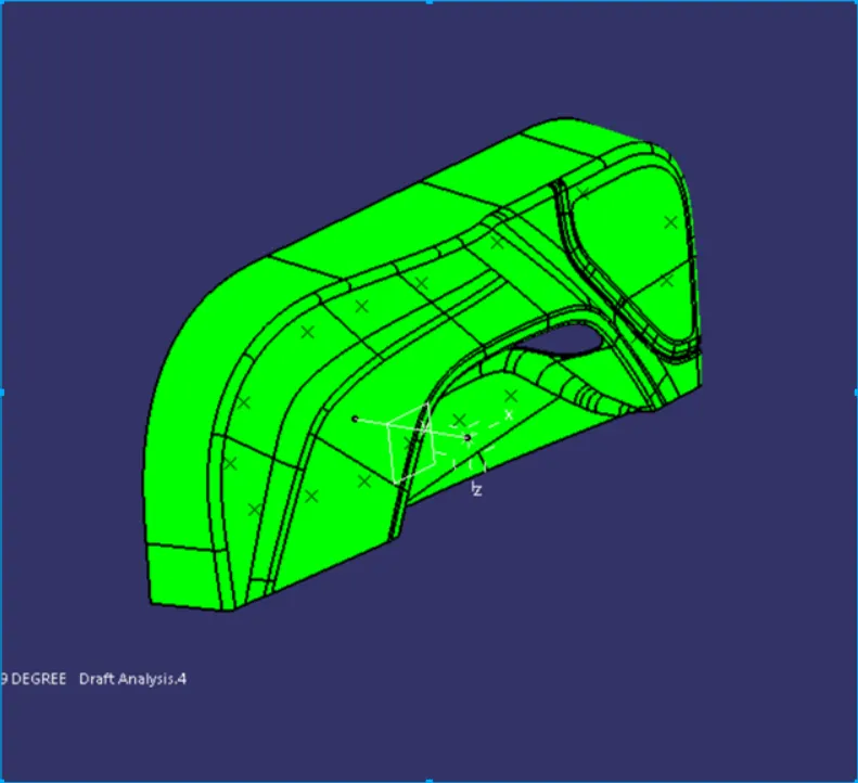
- CLASS A Surface draft analysis
Our class A surface is error less according to draft angle which is 3 degree.
- Final component Draft analysis with 3 degree draft
Our final component some places have red color means 0 degree draft real feel and there will some erosion during punch and die removing. Blue color shows the impossible to draft the component.
- Draft analysis on locators and Heat stakes with 0.49 degree draft.
I have made the all heat stakes and locators at 0.49 degree draft which is showing green and can made easily in draft direction.
Conclusion: My Door Trim part is ready for manufacturing.