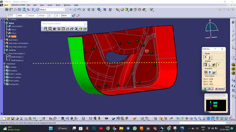
Week 10 - Challenge 3 - Door Trim Lower with Engineering Features
AIM
To create the Door Trim Lower Plastic component through the given Class-A surface and to create the Heat Stakes and the locators considering the design rules
Class A
Visible surface is a Class-A surface. It provides the style team's look for the component, which the part design engineer uses to develop the component with all of the engineering requirements.
Check for continuity of the given surface using Join or Boundary commands.
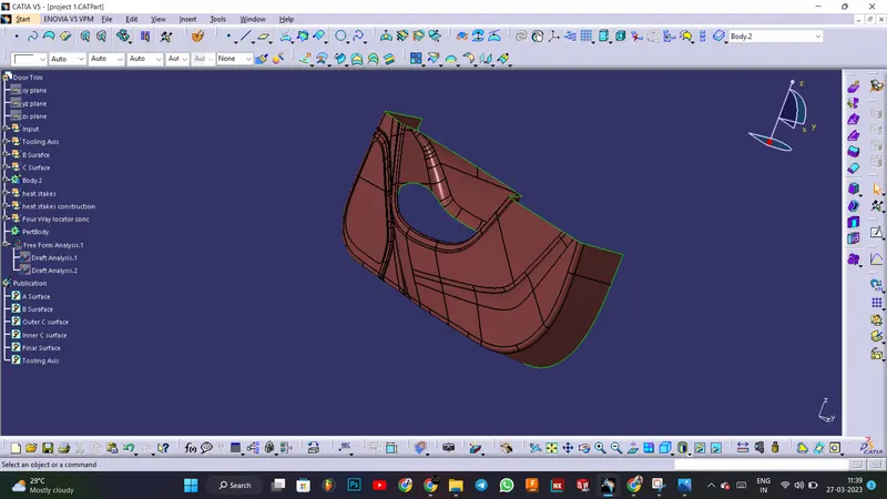
Tooling axis-Bisecting line Method
Using a dummy tooling axis, the bisecting line method is essentially used to identify the correct tooling axis. When using the bisecting line method, a line is utilized to either bisect the two lines or indicate an error, indicating that the two lines are parallel. We intersect the surface with the appropriate plane to determine whether or not the surface is toolable. This produces a drawing with two lines, which we can then bisect to produce a third line at the intersection of the two lines.
Draft Analysis of class A
Use the Featured Draft Analysis tool in the tools to now analyse the draft. After locating the compass and aligning it with the tooling axis, click on the lock symbol after aligning, and then click again on the surface after opening the draft analysis tool box.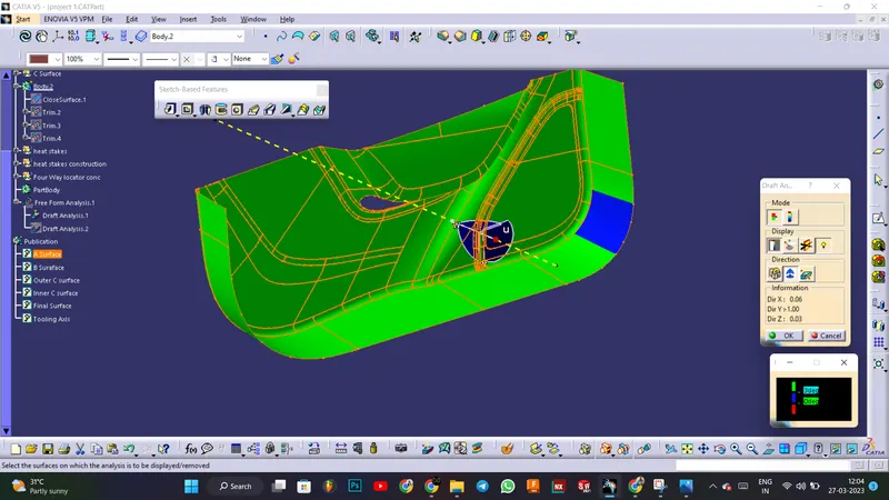
Creating Class B Surface:
First, offset the surface to 2.5mm, some errors may occur and some parts got removed. Click keep all sub-elements. And use fill, sweep, boundary, extrapolate, and trim commands to close the patches. Then join all together
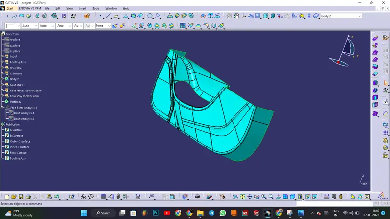
Creating Class C Surface:
At first extract the boundaries of the Class A surface and B surface, and use the sweep option to create the c surface
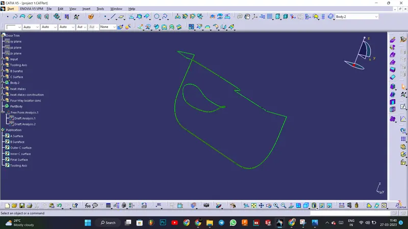
Final output :
Now trim the Class A , Class B and Class C surfaces to get the desired output. And make it as a solid body using close surface feature in part workbench.
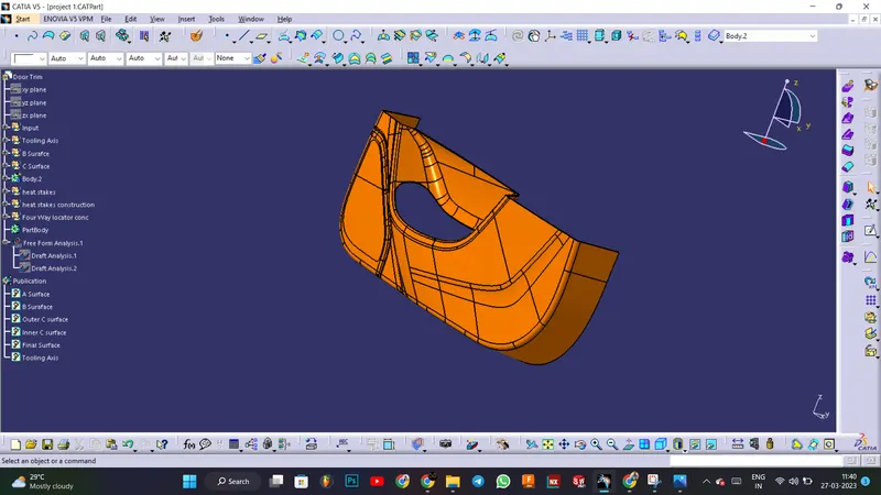
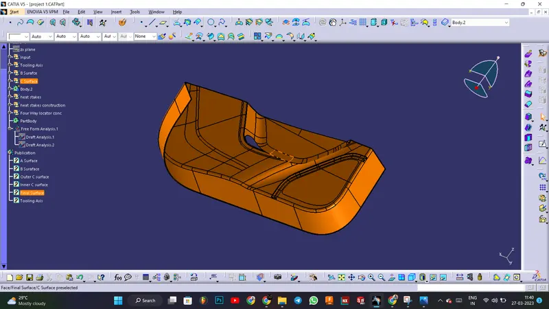
Creation of Heat stakes
Create a plane for the heat stake and draw the sketch of the heat stake and extrude it a solid and create stiffeners for the heat stakes and join them using union trim.
Make copies of the heat stake and translate it to all the provided locations
Creation of four way locators
Create the sketch in the plane and extrude it into surface and make as solid using the thicken.
Create Champfer on 4 sides and fillet the edges. Make a copy and translate to the another given location
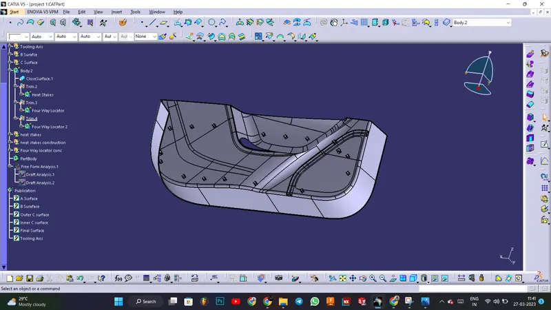
Final Draft analysis
Use the Featured Draft Analysis tool in the tools to now analyse the draft. After locating the compass and aligning it with the tooling axis, click on the lock symbol after aligning, and then click again on the surface after opening the draft analysis tool box.