Week 10 - Challenge 2- Attachment Feature Creation (Dog House)
AIM: To design the Door Trim component along with it's Dog Houses through the given Class-A surface. To start with the design, the tooling axis for the given Class-A Surface is created meeting the requirements of the draft angle and at the end perform the Draft analysis on the model.
OBJECTIVE: To design the Door Trim component design from 'Close Surface' through given Class-A surface given in .CATPart. This can be done by designing Class-B and Class-C surfaces then trimming both the surfaces to get the actual closed surface. Then designing the required Dog Houses considering the design rules mentioned in videos and in this question. The proper Tree Structure of the model is ensured. Publication is done by using the publication option by publishing the above Tooling Axis, Class A, B, and C surface from the Tree Structure. The sketches are Positioned Sketch and are ISO constriained.
DESCRIPTIONS:
Class A: It is the surface that is created by the concept sketches made by free hand sketchers. The finalised sketch is then fed to the computer and a 2D surface is created out of it by the use of a software like Alias. This computerized design is known as Class A surface.
Class B: It is a reference surface that is created by the design engineer and is a copy of the class A surface that is at a distance equal to the thickness of the part.
Class C: It is again a reference surface that is created by the design engineer to connect Class A and Class B surface also known as the side wall of the surface.
Dog House: It is an engineering feature used in plastic design which are used as support feature. Other engineering features like snaps, locators, and screw bosses are mounted on them to increase their strength. Dog houses are subjected to draft analysis to prevent breakage of the component during ejection from the mould cavity. Dog house and other engineering components are built on the B-surface.
The technique that is used to create the model is to initially create a CLASS B surface at a distance equal to thickness(2.5mm taken here) and later a vertical surface CLASS C. Then the three surfaces were trimmed to obtain the required part.
PROCEDURE:
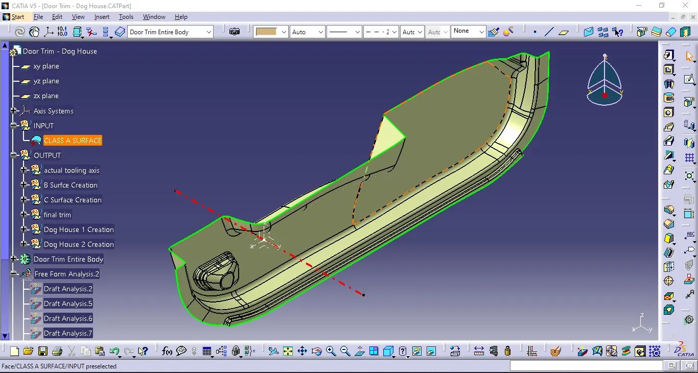
Class A Surface:
1) Open CATIA V5.
2) Open the downloaded 'Door Trim - Dog House.CATPat' in CATIA.V5 having the CLASS A SURFACE.
3) The CLASS A SURFACE was given it's shape and was saved as a .CATPart.
Tooling Axis:
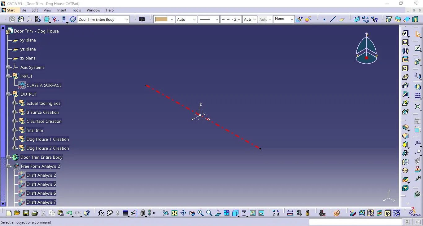
1) The surface where we want to make the tooling axis is extracted with Extract command.
2) Then a point was made at the middle of the extract.
3) A line was drawn out on the point perpendicular to the extract along Y-axis. That line was taken as dummy since it was showing negative clearance.
4) An intersection was made on the same point along X-axis on the entire part.
5) Then two lines alongside the sides of intersections are made for the perpose of making an actual tooling axis through Bisecting method.
6) Then a line between the two lines at that point is drawn through Bisecting method to get the actual tooling axis.
Class B Surface:
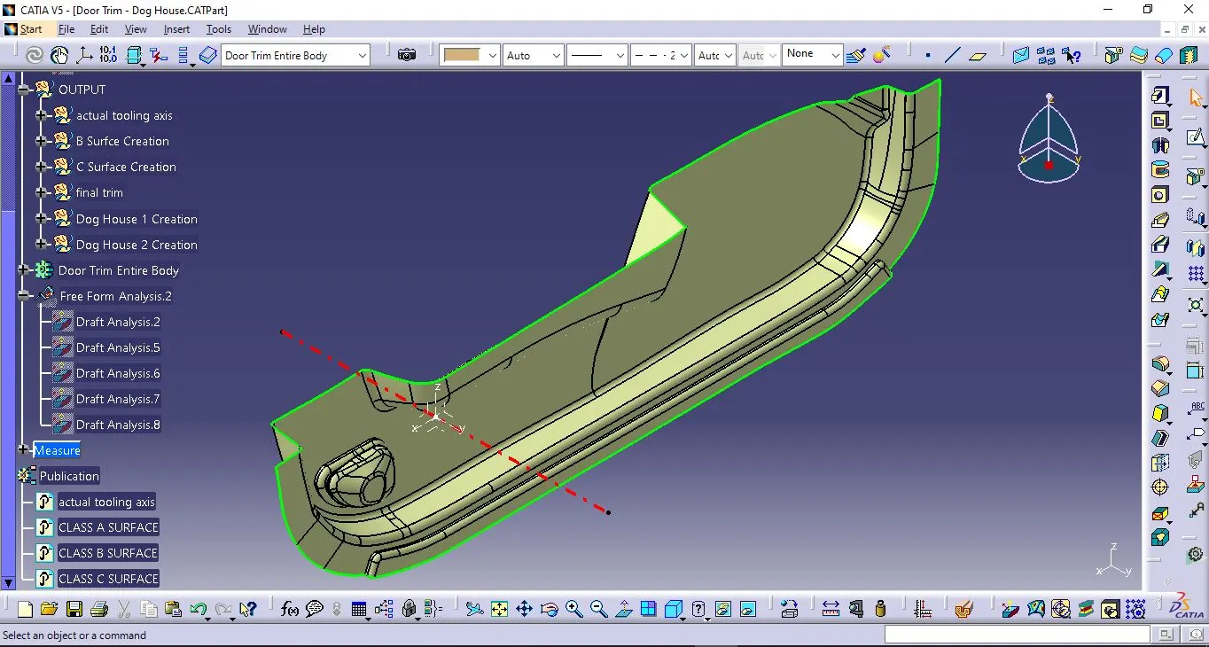
1) One of the outer surface of CLASS A SURFACE was extracted surface by surface.
2) The entire surface was the offsetted below CLASS A SURFACE at 2.5 mm distance.
3) The surface which was not offseted was later filled with Fill command.
4) The filled and offsetted part was joined with Join command.
5) The joined part was given boundary with help of Boundary command for furthur operations.
6) After the trim operations, give a fillets of radius of 6.9 mm and rest operations like extrapolations and that extrapolated part was named CLASS B SURFACE.
Class C Surface:
1) The boundary of each opening edges consisting of all four edges at the corners are obtained.
2) Then all those boundaries are subjected to swept operation with Swept command with different draft angle each.
3) Then the sides of all those swept components bounded are later extrapolated sideways.
4) Those extrapolated parts are then trimmed to each other to get a combined swept surface.
5) That combined swept surface is joined with CLASS A SURFACE and then we find something that we named as CLASS C SURFACE.
Final trimming:
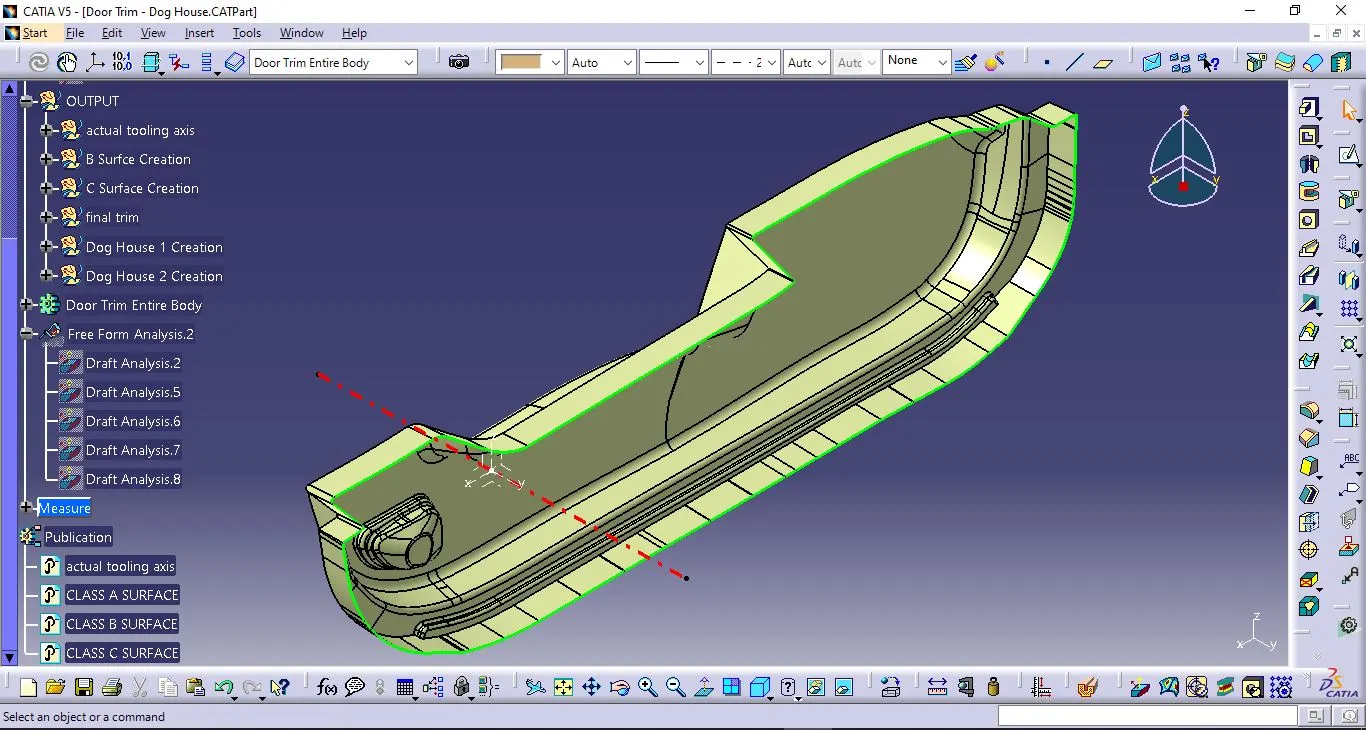
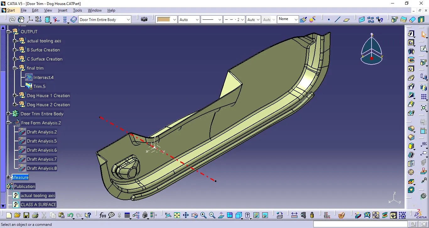
1) All the surfaces made i.e. Class A, B and C were made visible for further operations and intersected to see any further non-intersections between those three.
2) Then the surfaces were trimmed to get a model of 2.5 mm thickness(T).
Dog House:
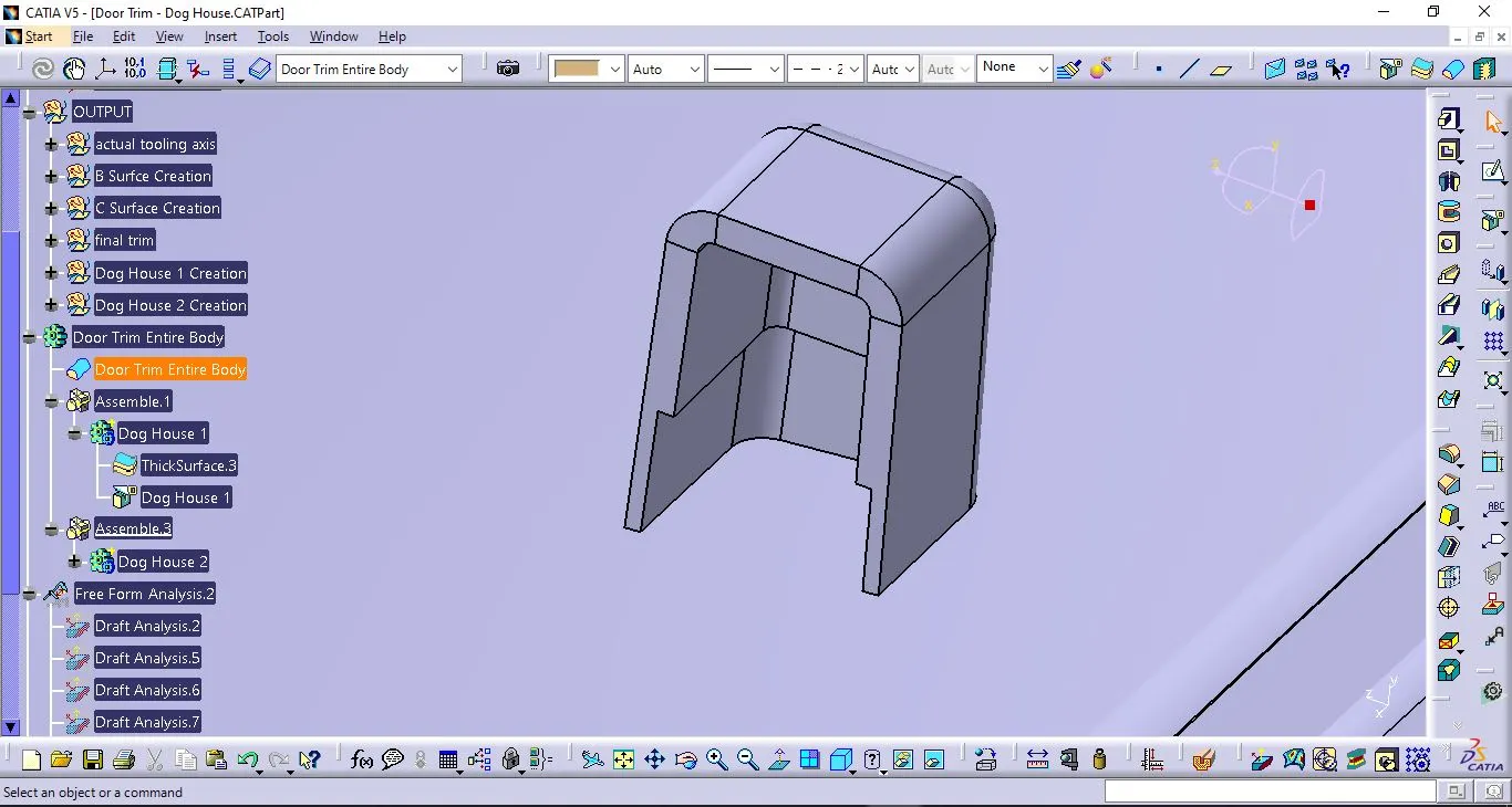
1) The surface where dog house should be created is extracted through Extract command.
2) On that surface a sketch was drawn with wisth of 6*2=12 mm at a distance of 124 and 25mm respectively from axis.
3) Through that sketch extruded a sweep through Sweep command at an angle of 1.5 degrees at a distance of +21 mm and -1 mm respectively.
4) The point where the reference was set for the position of the dog house was used to draw a line along Z-axis. Through that line an extrude was drawn along X-axis.
5) That extrused part was later offsetted at 20mm distance and then trimmed and splitted to get the dog house.
7) The faces were selected and filleted at radius of 1mm.
8) In part design, that surface was later thickened with Thick Surface till 2mm.
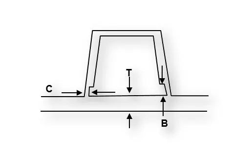
9) Then the inner part of dog house was extracted with Tangent continuity. That extract was offsetted at a distance of C=40% of T=0.4*2.5=1mm.
10) Then that extruded part below dog house is reused to extrapolate at a distance of B=3 to 6mm=4mm.
11) The two extrapolated surfaces were then trimmed to get a surface which later extrapolated and used in that thickened part to get the final design of the Dog House.
12) Then that dog house is assembled with door trim. The same process is done for another dog house with different position.
Specification of Dog House:
'C' is where the doghouse contacts the backside of the surface
Doghouse wall thickness at the intersection of the part wall (C) should be 40% or less than the main wall stock (T).
The height of (B) should be between: 3.0 – 6.0 mm
C: 40 % of T or ≤ T
B: 3 - 6 mm
Width: =>12 mm
Width to Height Ratio: 3:1
Draft: 1.5
Draft Analysis:
1) In plastic design, the draft analysis or angle that is considered in the OEMs (Original Equipment Manufacturer) is 3 degree.
2) First thing to carry out was to select the compass and set it on the tooling axis in upward direction.
3) By clicking on the surface, the whole part turned into green colour. If blue was visible that meant that the analysis was inversely done so just by flipping the direction, draft analysis.
4) Then the hollow part was lat
er created into a solid body by going the part body option and then selecting close body surface.
5) We can see draft analysis on the solid part resulted in green colours.
6) The green region shows the part which is toolable or produceable by the molding machine and the draft angle is 3 degree.
7) Blue colour region states that the part can be allowed in some OEMs but still need to be improved for the other OEMs as the draft angle is more than 3 degrees.
8) Red colour which is there in this case states that the draft angle is less than 3 or 2.8 degree and cannot be produced or if produced would be faulty.
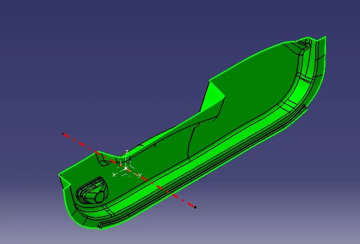
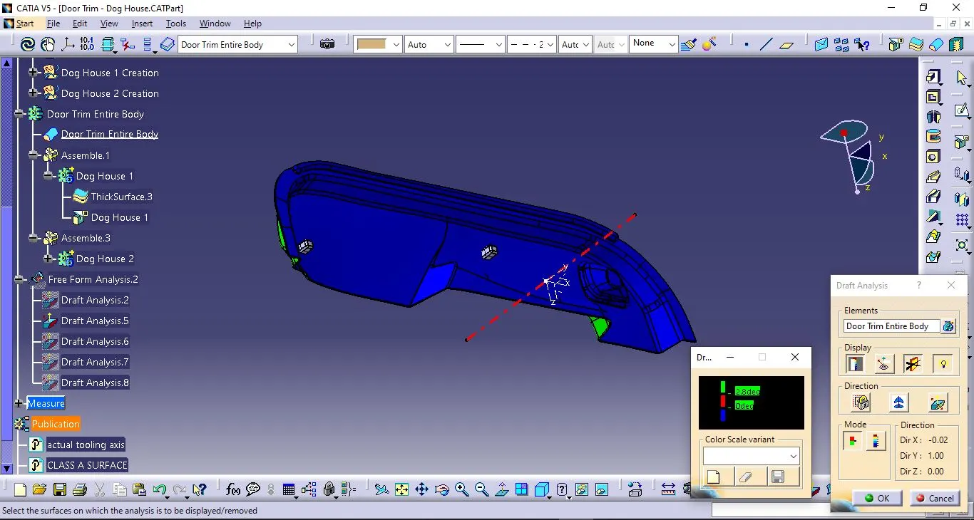
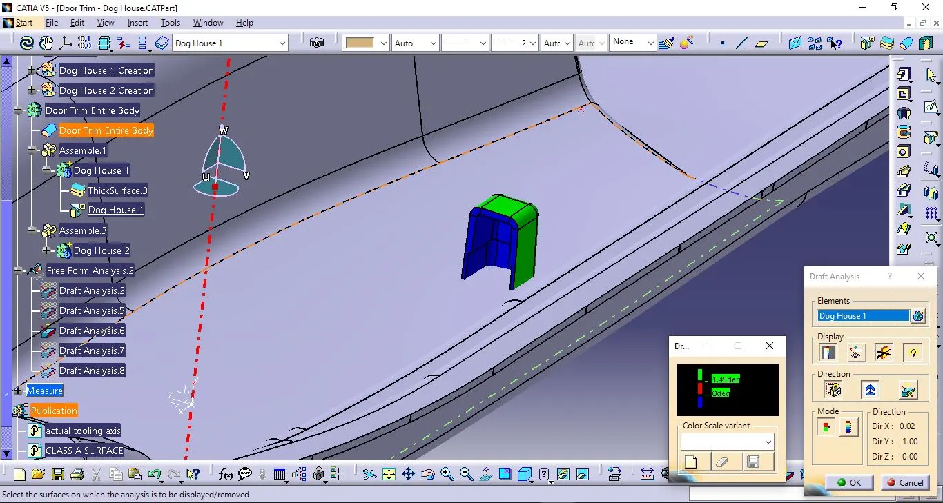
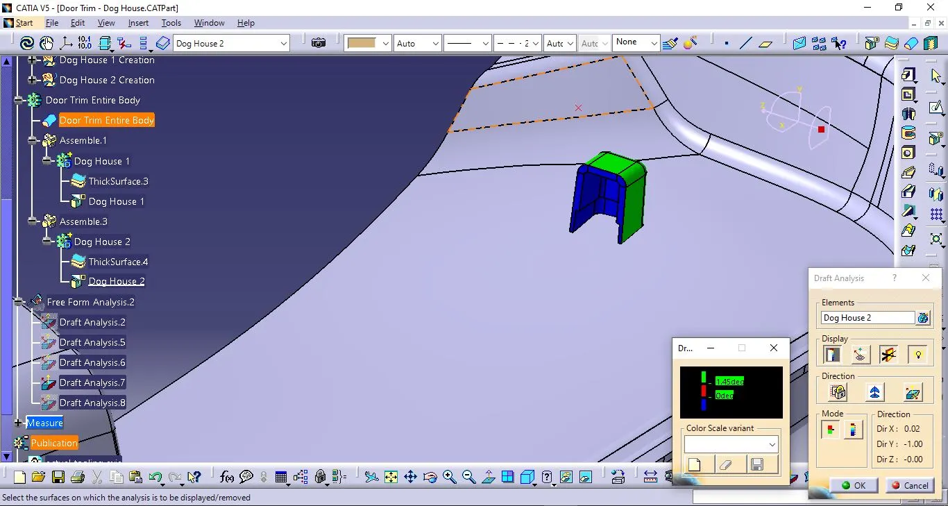
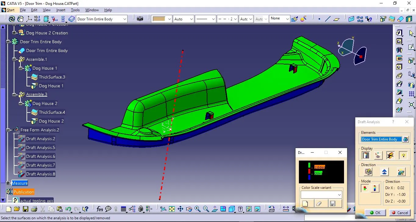
NOTE: The tooling axis was adjusted in such a way so that to mitigate the red colour fault as much as possible and get desired design to get the draft analysis correct.
OUTPUT:
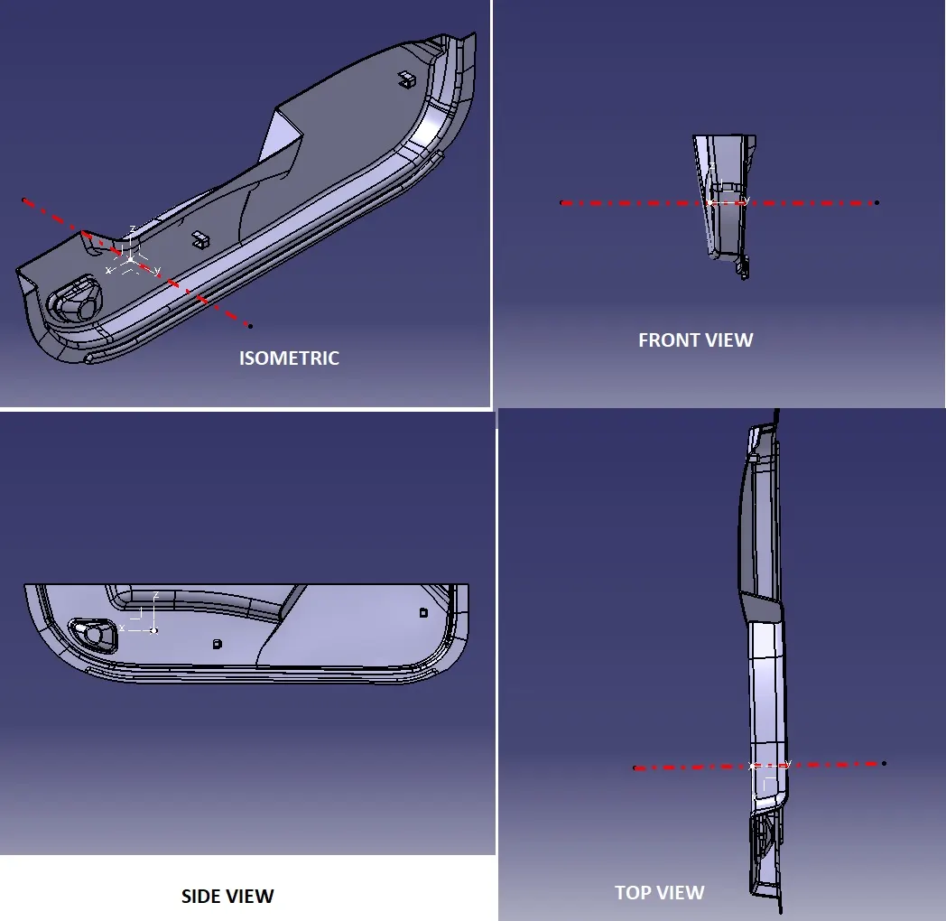
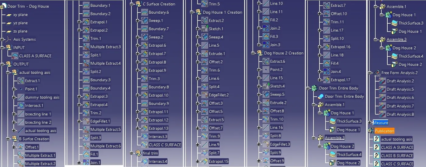
The outputs are given below in the form of screenshots of .CATPart as instructed above in the question for the completed model from 14 - Week 10 - Challenge 2- Attachment Feature Creation (Dog House).CATPart:
a) 3D views:
b) Tree Structure:
INFERENCE:
The design was achieved through the tooling axis and Class A, B and C surfaces and doing the nessesary operations to get the closed surface. Next the thickening surface was solidified through 'Thick Surface' command. After that it's .CATPart was attached below and the entire report is submitted.