Week 10 - Challenge 2- Attachment Feature Creation (Dog House)
Challenge 2 - Attachment Feature Creation (Dog House)
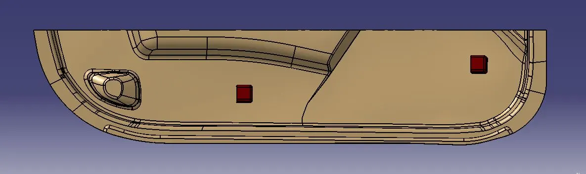
OBJECTIVE: To create a dog house feature on a plastic door trim component 3D Solid CATpart in CATIA from the given Class-A surface by meeting the requirements of the draft angle and the attachment feature guidelines.
MAIN PROJECT:
A) Door Handle Plastic Design:
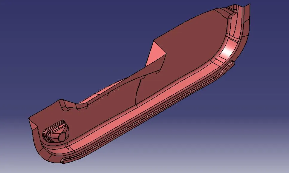
Given: Class-A Surface
Class-A surfaces refer to high-quality surfaces on a product or tooling that are critical for achieving a flawless and aesthetically pleasing finish. This surface emerges from the creative strokes of freehand sketchers by visualizing the essence of conceptual ideas. The precisely refined sketch is subsequently digitalized, and seamlessly transformed into a sophisticated 3D surface through the utilization of specialized software such as Alias.
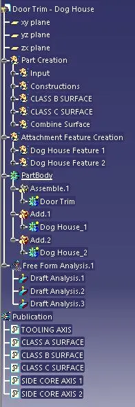
High-Level Tree-Structure of 3D CATPart:
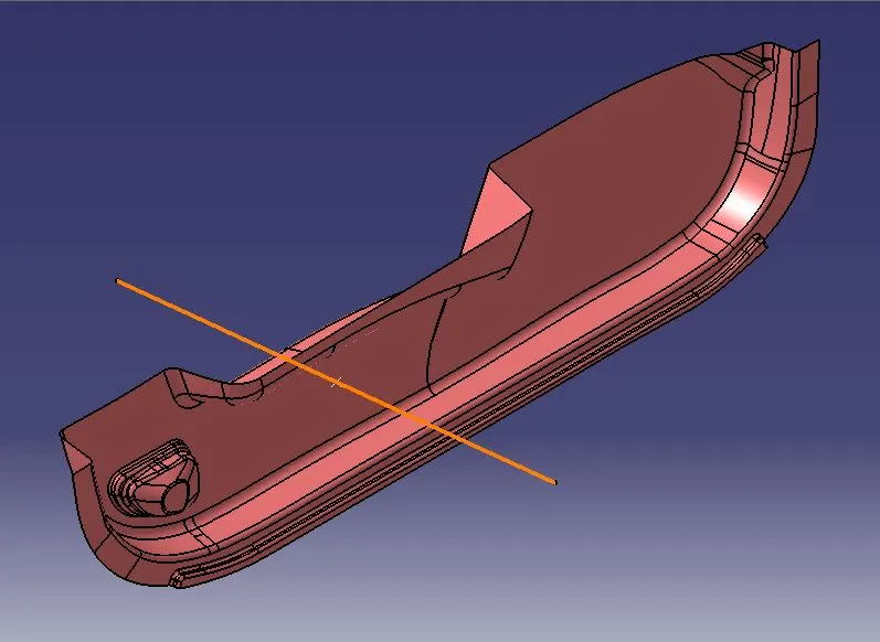
Tooling Axis:
The term tooling axis refers to the primary direction along which a mould moves during the manufacturing process. This is particularly crucial in processes such as injection moulding, where the molten plastic material is injected into a mould cavity to form a finished product.
Tooling Axis Creation:
STEP-1: Create a "Constructions" geometrical Set and construct a point on the origin (which also lies on the Class-A Surface). Draw a line along the x-axis direction and consider it as a dummy tooling axis.
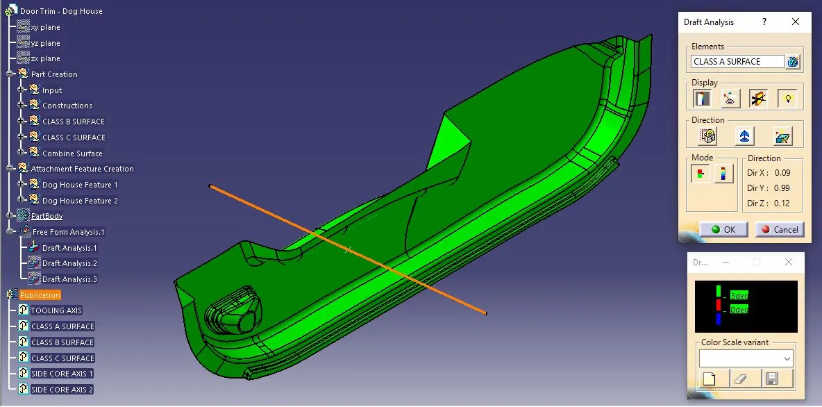
Class-A Surface Draft Analysis:
Before generating the part model, conducting a Class-A Surface draft analysis is important to check the manufacturing complexity and to ensure and understand the potential challenges.
Drafting possibilities based on various axes.
X-axis: Not possible to produce.
Y-axis: Cheap and easy way to produce the component.
Z-axis: Not possible to produce.
Class B Surface:
Class-B surfaces are interior surfaces of the part body and it does not require the same level of visual perfection as Class-A surfaces. While Class-A surfaces are primarily concerned with flawless appearance and are typically used for visible exterior parts of a product, Class-B surfaces are utilized for areas where visual perfection is not as critical as it may also contain B-side features like ribs, screw bosses and dog houses.
Class-B Surface Creation:
STEP-1: Create a "Class-B Surface" Geometrical Set and offset the Class-A Surface by 3 mm inwards.
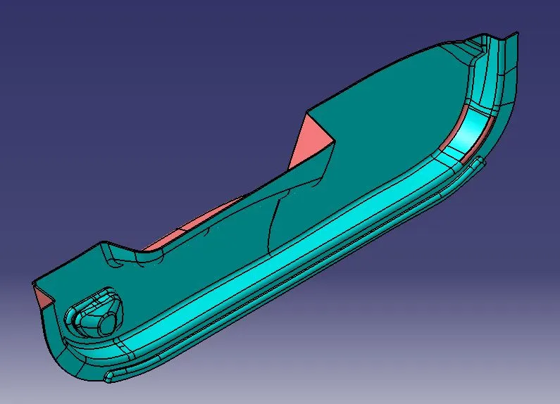
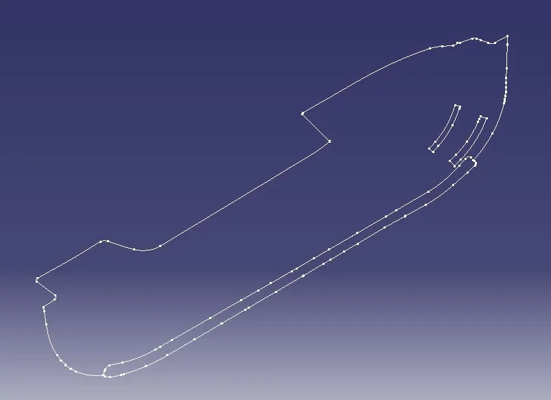
STEP-2: Take a boundary on the offset surface to know where the surfaces are missed to generate on offset operation.
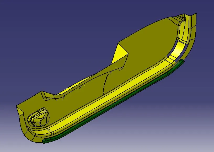
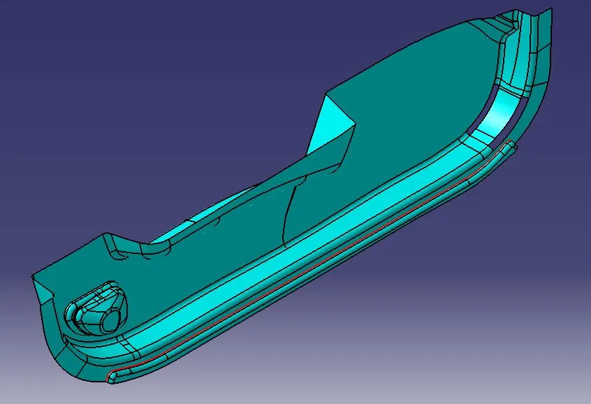
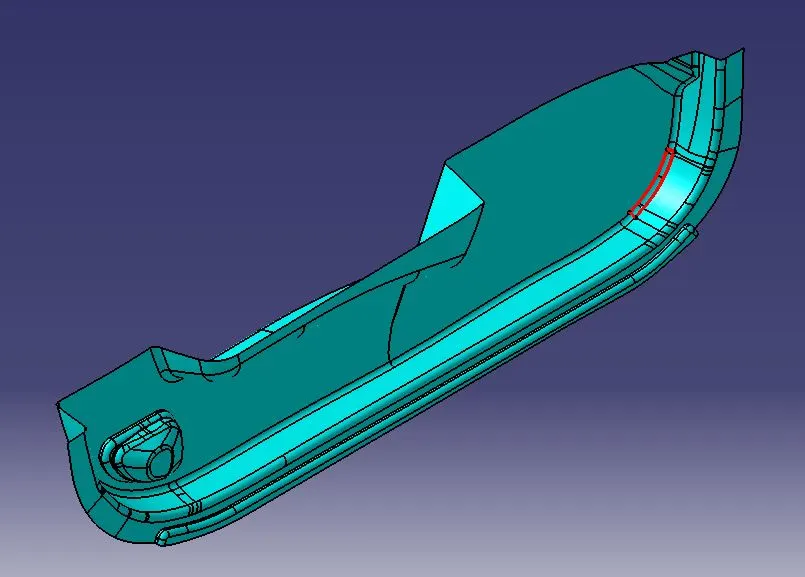
STEP-3: The surface discontinuities between the surfaces are rectified by extracting the offset surface into two parts (use the fillet section as separation criteria) and extrapolating the surface edges by 5 mm to ensure that the surfaces intersect each other. Then trim them to form a single surface. (The highlighted red line is the intersection of the two surfaces)
STEP-4: As some surfaces are missing on the fillet section, use the Join command with the "sub-elements to remove" option and remove the fillet area. Take a boundary of both edges and use the Blend option to connect the surface.
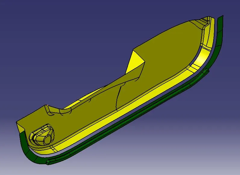
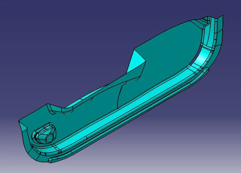
STEP-5: The remaining missed surface is formed using the Multi-Sections Surface command and joined with the main surface to form a proper Class-B Surface and publish it so that it will be easy to view for future reference.
Class C Surface:
Class-C surfaces are primarily functional and may have fewer aesthetic requirements compared to Class-A surface. These surfaces are often used in areas of a product where appearance is not a significant concern, and the primary focus is on meeting functional and manufacturing requirements.
Class-C Surface Creation:
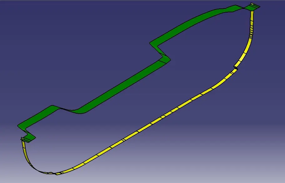
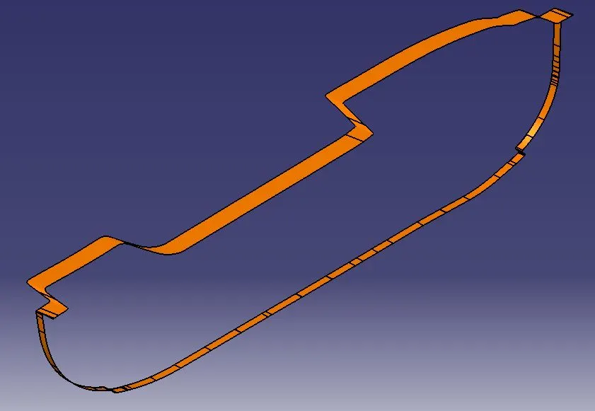
STEP-1: Create a "Class-C Surface" Geometrical Set and take boundaries with limits one by one on Class-A Surface as shown in the below image. Then generate a surface using the sweep command across each boundary with a 3-deg draft angle along the tooling axis as draft direction. The generated surface direction should be towards the Class-B Surface.
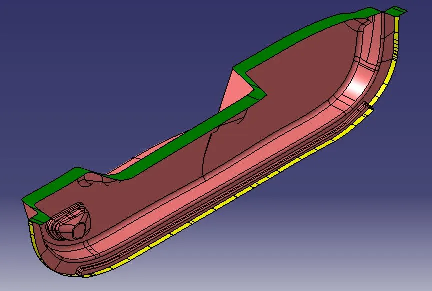
STEP-2: Extrapolate each connecting edge of the generated Class-C Surface up to a certain mm so that the surfaces intersect each other. Then Trim them to form a single surface.
Part Body Creation:
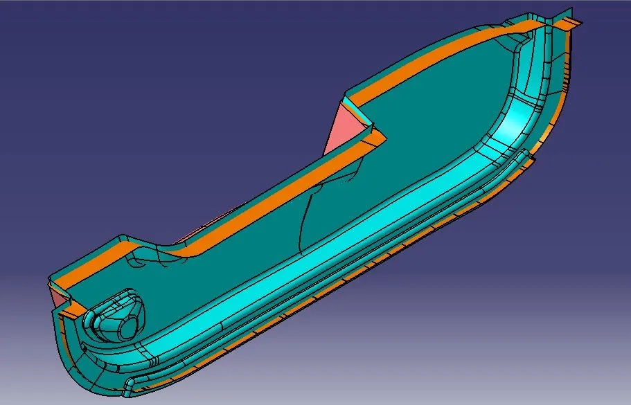
STEP-1: Join the Clas-A and Class-C surfaces and trim them with the Class-B Surface. If it fails at trim operation, take an intersection between conjoined Class-A and Class-C surface with the Class- B Surface and check on the non-intersection area, then extrapolate the Class-B Surface at the non-intersection edges and repeat the same until the Closed surface formation.
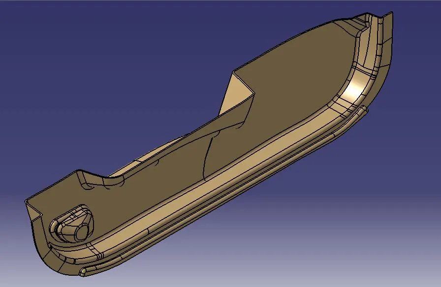
STEP-2: Finally, the Door Trim Plastic component 3D Solid is created by the Close Surface command.
STEP-2: Attachment Feature Creation:
Dog House Feature:
Design Rules:
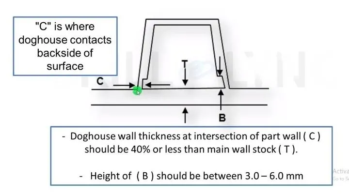
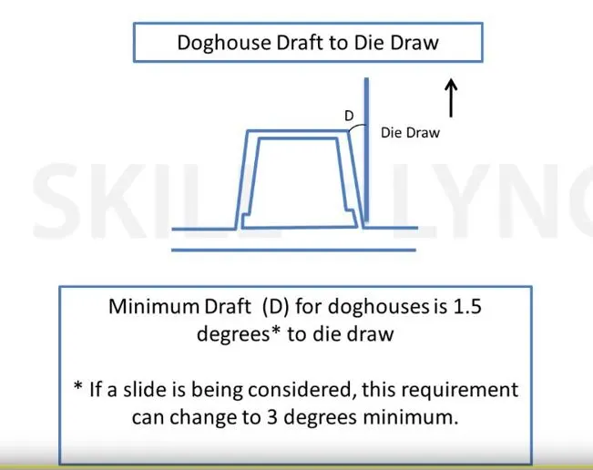
STEP-1: Extract the base surface from the part body and draw a line normal to the surface for the tooling axis. sketch the dog house profile position using the Positioned-Sketch method.
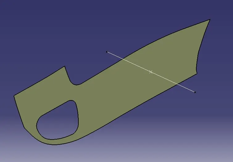
STEP-2: Create a plane tangent to the surface and sketch the dog house profile position using the Positioned-Sketch method.
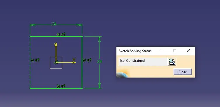
STEP-3: Construct a sweep with a 1.5 deg draft angle along the tooling axis and cover the top surface using the Multi-Sections Surface command. Then thicken the surface up to 2.5 mm outwards using the Thick Surface command.
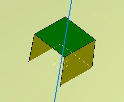
STEP-4: Construct a side core axis by normal to the surface and take a draft of 0.5 deg to maintain the design rules.
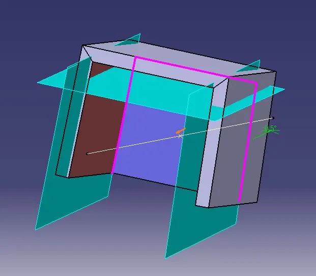
STEP-5: Split a portion from the part using the Split command as per the design rules of 40% nominal thickness and 3-6 mm height for the dog house. Then provide a fillet at the inner and outer edges.
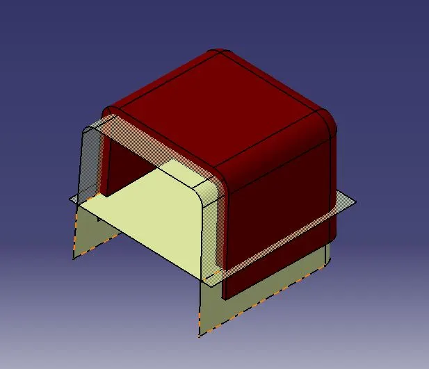
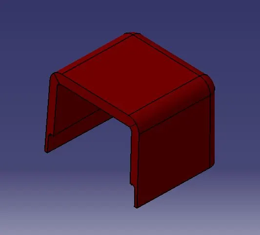
STEP-6: Follow steps 1 to 5 and create another dog house at another position.
Part-Body Draft Analysis:
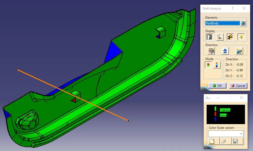
Draft analysis on the solid part resulted in green and blue regions.
1) The green region states that the part is toolable or produceable by the molding machine and the draft angle is 1.5 deg for the dog house.
2) The blue colour region in the part is shown as the tolling axis direction is opposite to the surface, which is not an issue.
3) The red colour which is not there, in this case, states that the draft angle is less than 3 degrees and cannot be produced in a normal quality moulding machine even though if produced it will result in faulty.
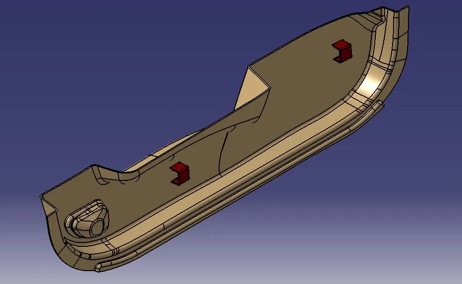
Various Views of Base Bracket:
Isometric View:
Front View:
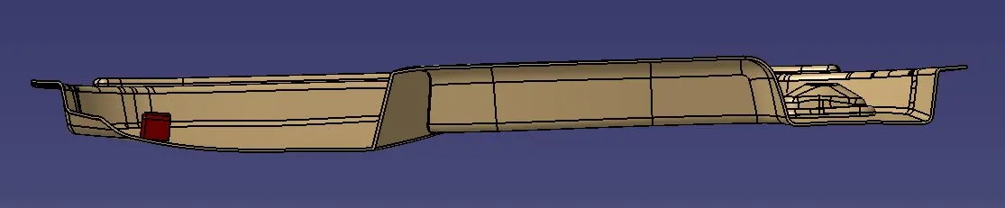
Side View:
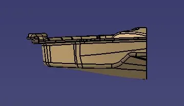
Top View:
Conclusion:
Thus, the Door Trim Plastic 3D component is created with the 2 dog houses in Catia software by following the design guidelines and standards.