Week 10 - Challenge 2- Attachment Feature Creation (Dog House)
AIM:
To create the Dog House for the Door Trim Considering the design rules.
OBJECTIVES:
- Consider the thickness of the part should be 2.5mm
- 'C' is where the dog house contact the back side of the surface
- Dog House wall thickness at the intersection of the part wall (C) should be 40% or less than the main wall stock (T).
- The height of (B) should be between 3.0 - 6.0 mm.
CLASS A SURFACES:
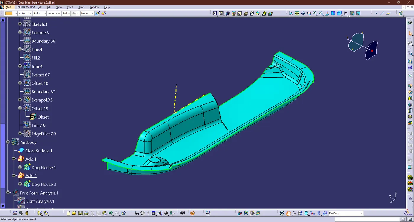
PROCEDURE:
STEPS FOR CREATING THE DOG HOUSE DOOR TRIM:
STEPS FOR CREATING THE DOOR TRIM:
- TOOLING AXIS:
- Manually arrange the view to choose the ideal tooling direction that covers the majority of the surfaces.
- Then create the boundary and made the point on the boundary line
- now create the line on the point and given name has "TOOLING AXIS"
- Then again create the line with perpendicular to the tooling axis and givEN name has "SIDE CORE AXIS"
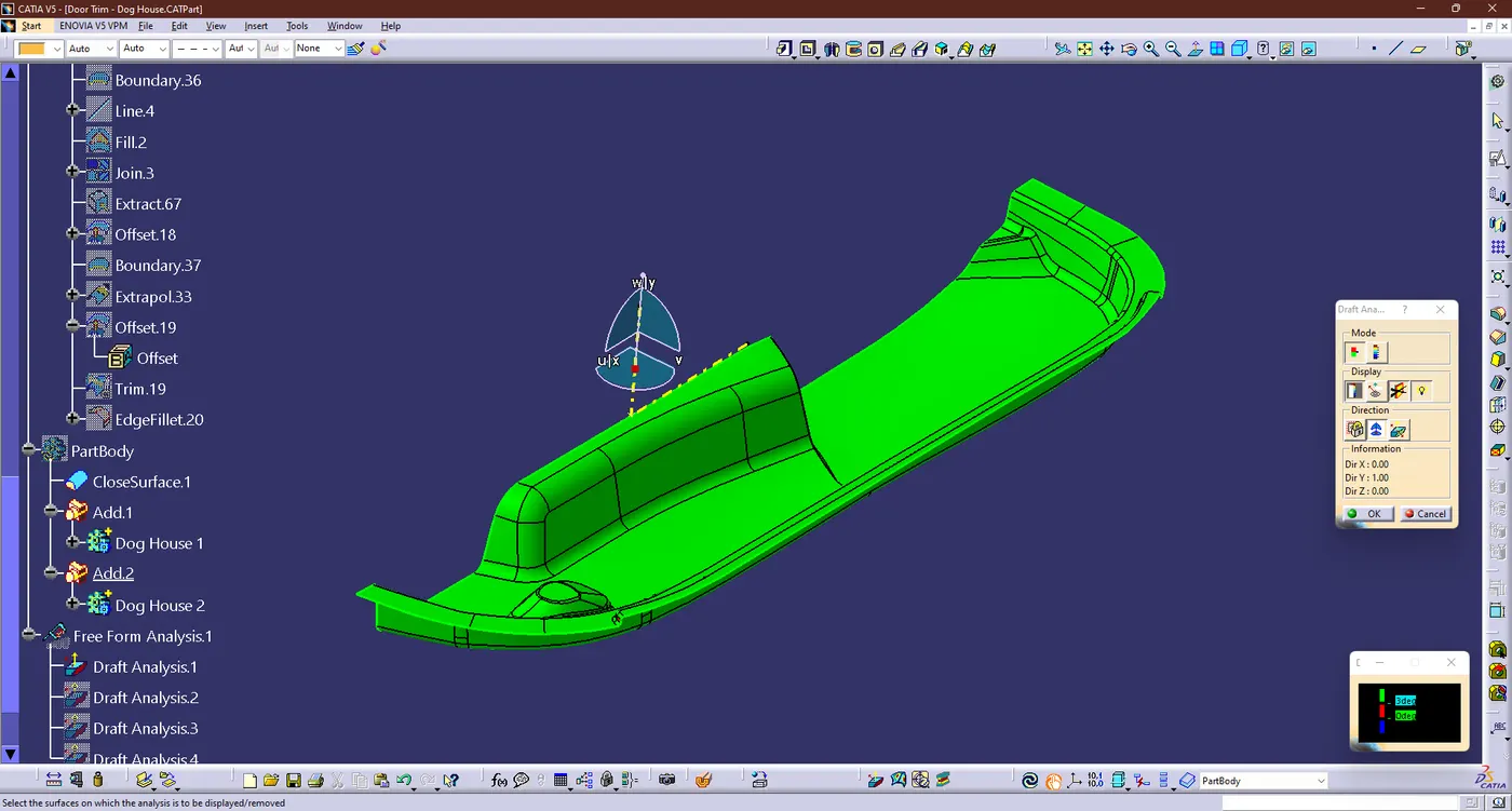
- DRAFT ANALYSIS:
You can determine whether the part you drafted will be simple to remove using the Draft Analysis tool. In this kind f analysis, Zones on the investigated elements are identified byy color ranges where the deviation from the draft direction at any given place corresponds to predetermined values.
- Go to customized view parameter, under mesh, check material, and then click ok before moving on to draFt analysis.
- Now for draft analyses go to insert » analysis » feature draft analysis.
- Set the draft direction using the compass.
- Change the draft angle on the color scale to 3 degrees.
- As a passing draft angle is indicated, the component turns green.
- Check the component's angle using running points.
STEPS FOR CREATING THE CLASS B & C SURFACES:
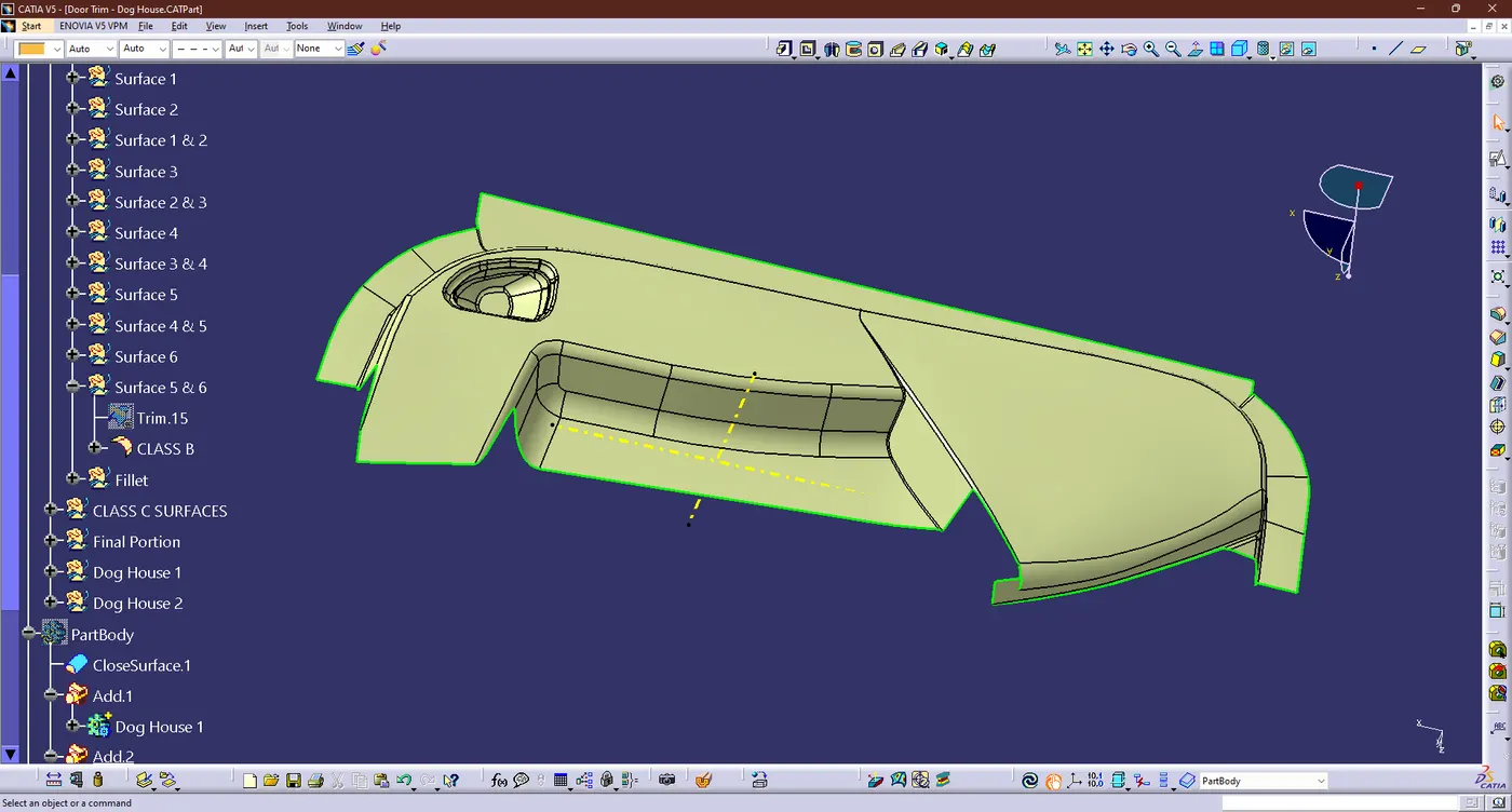
- CREATING B SURFACES:
- Let seperate the Class A surface for our reference to create the CLass B surfaces.
- Now Extract the each seperated surface from the class a surface.
- Then do change the each one by one now UNTRIM the surface
- create the boundary for the UNTRIM surface then extrapolate the surface
- Do the same thing for all the seperated surface
- An then final join all the surface and we got the "CLASS B SURFACES"
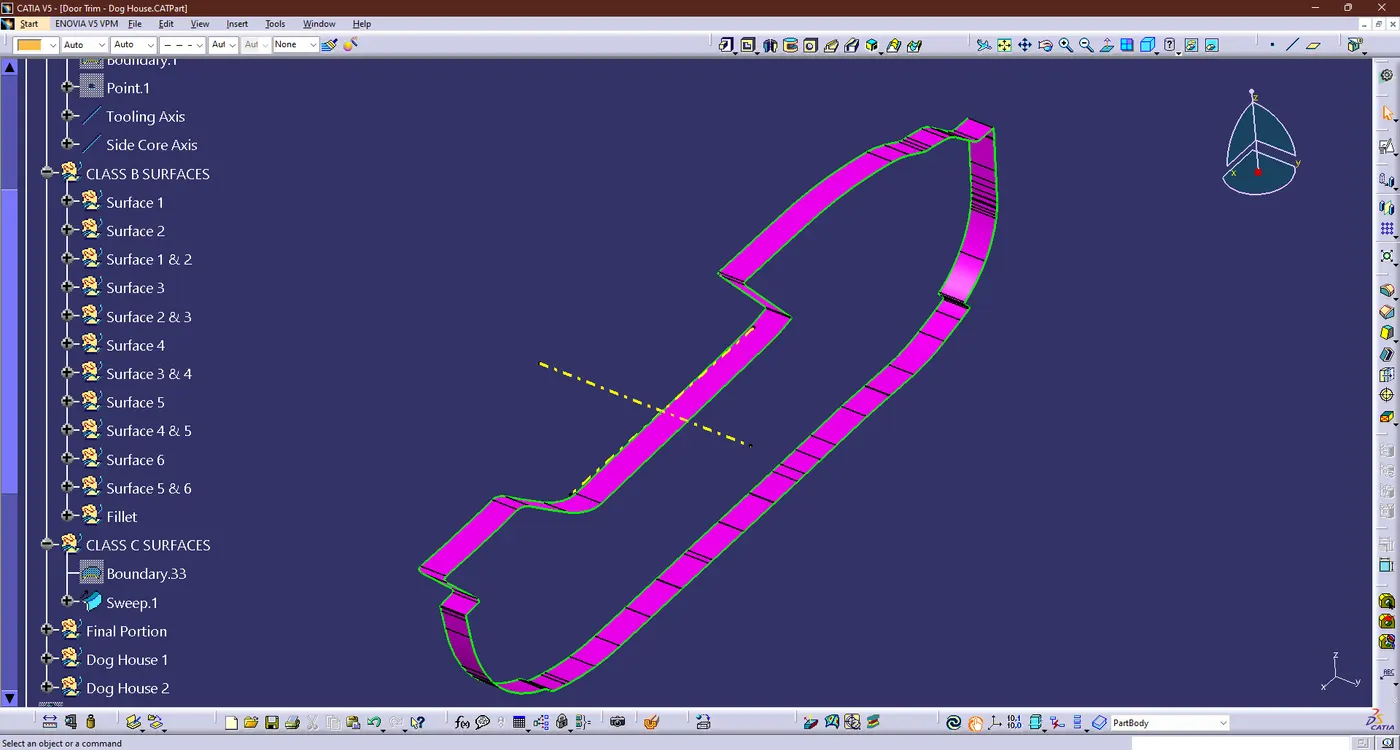
- CREATING C SURFACES:
- Now Extract the Boundary from the CLASS A surface by using the Boundary Command
- Then create the surface for the boundary line by using the sweep command it should lies on the toolbar
- An extrapolate the full surface using the Extrapolate command due to it will merge the both CLASS A & B Surfaces.
- FINAL PORTION:
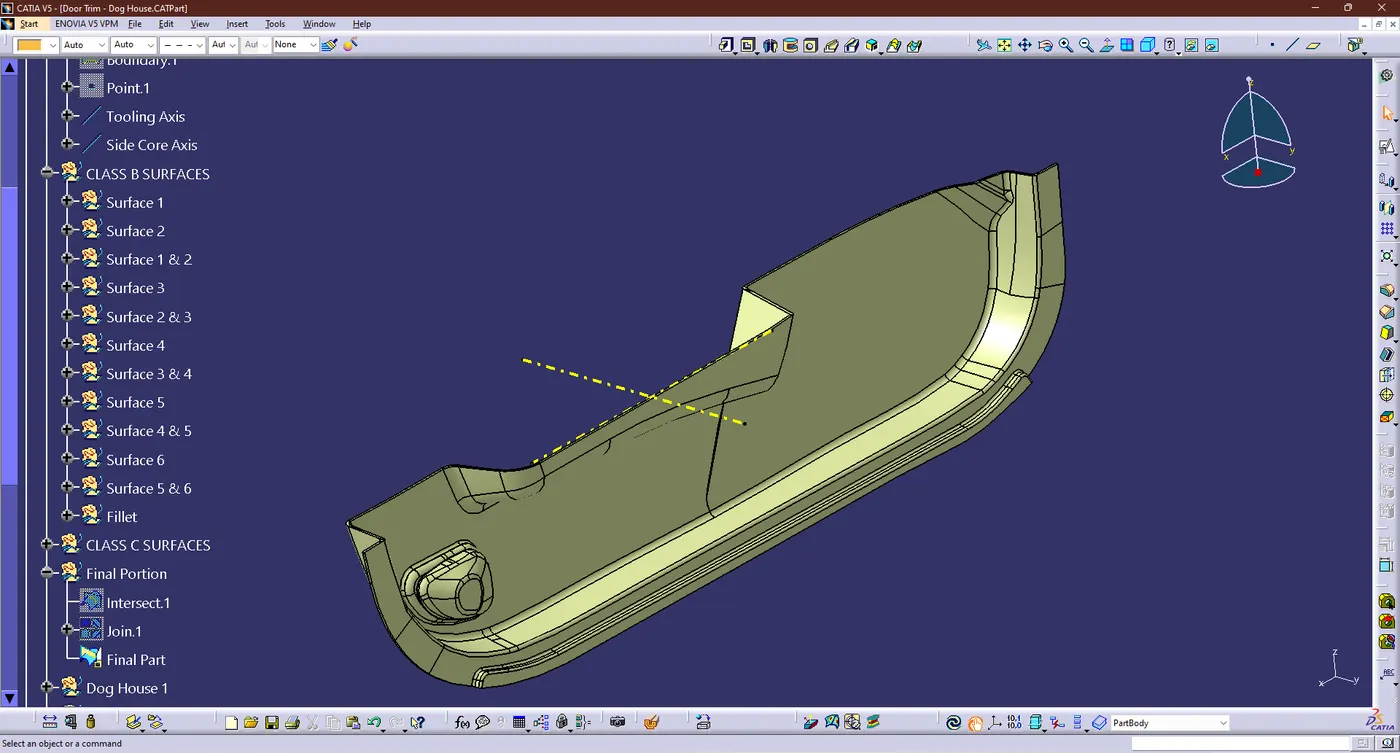
- Now join the surfaces like CLASS A & C surface
- Then do Final tirm CLASS B & A,C and the output will be like this,
- SOLID BODY:
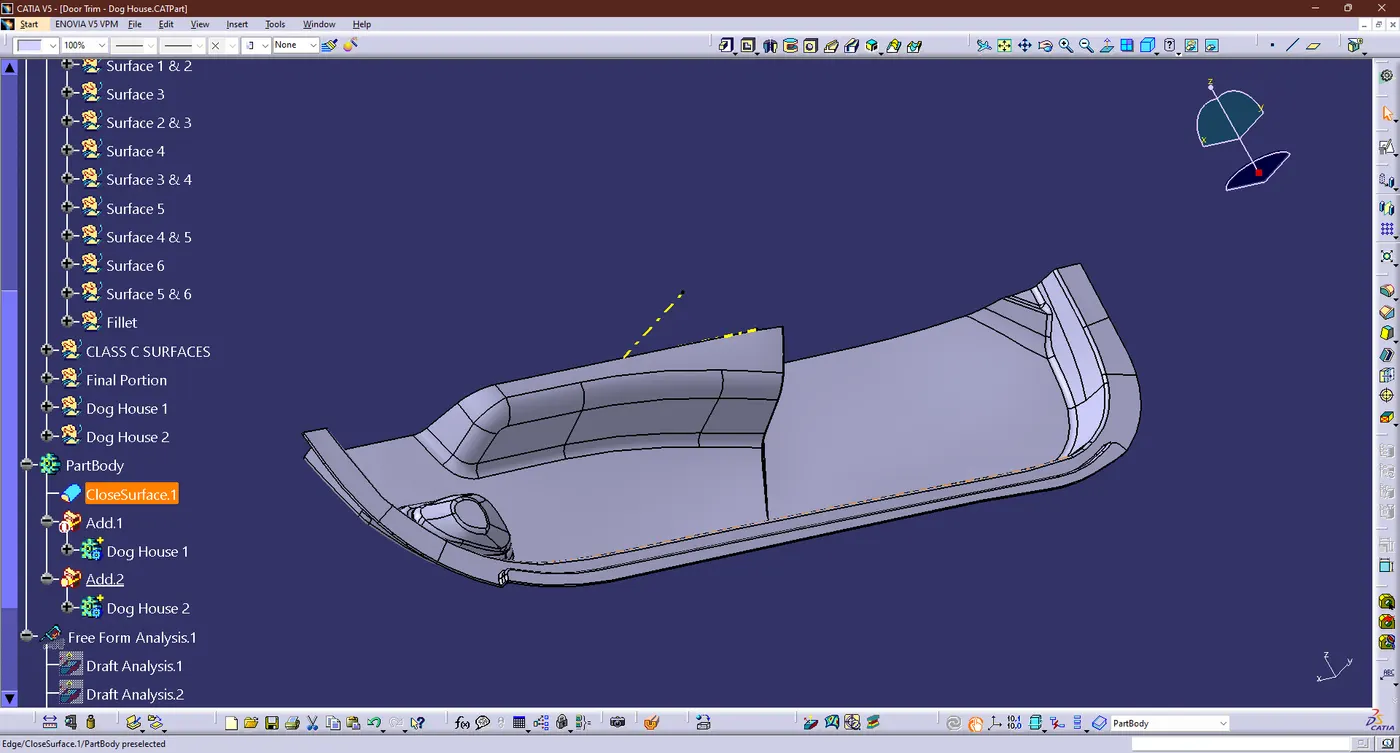
- The hollow is then created as a solid by selecting the Body option and then selecting the Close body surface and hence we got the final output were mention below
- CREATING THE DOG HOUSES:
- Draft has 0.5 deg per side
- 'C' is where the dog house contact the back side of the surface
- Dog House wall thickness at the intersection of the part wall (C) should be 40% or less than the main wall stock (T).
- The height of (B) should be between 3.0 - 6.0 mm.
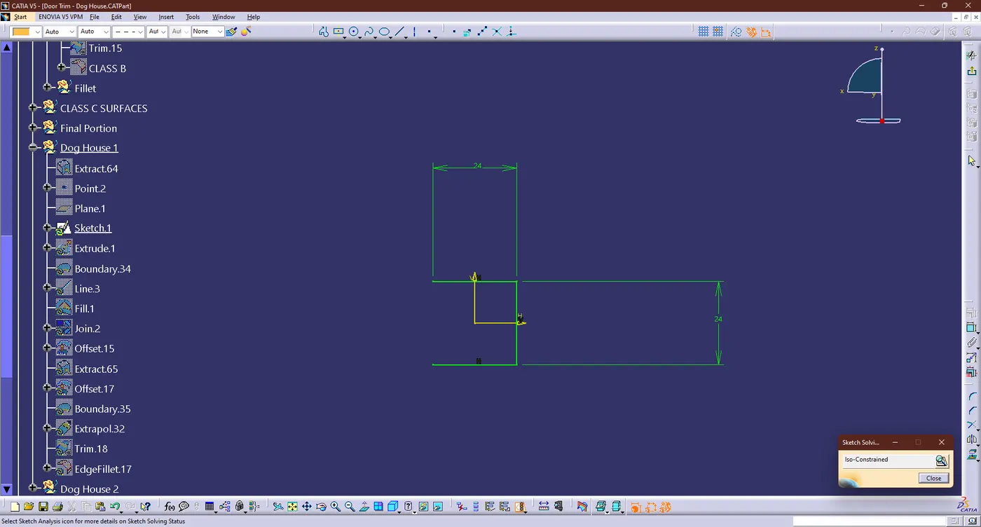
- Create a sketch that is positioned for the ribs and extrude it in accordance with the tooling axis another method is to create a thicken pad in accordacne with the tooling axis.
- Then create another sketch for the second dog house and do for the same procedure for the previous one
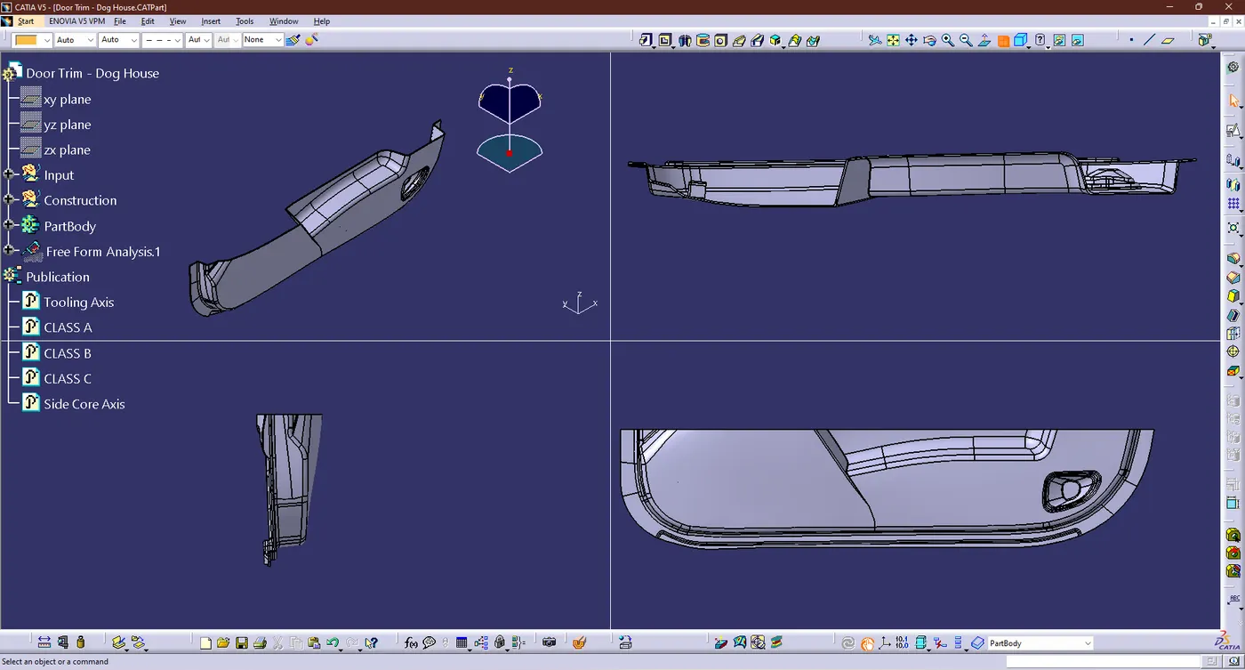
- FINAL PARTBODY AFTER CREATING THE DOG HOUSE:
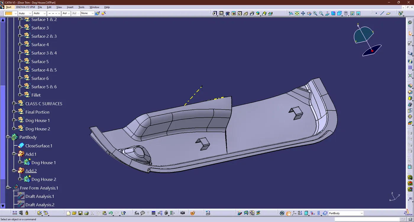
- DIFFERENT ORIENTATION WERE MENTION BELOW:
- DRAFT ANALYSIS:
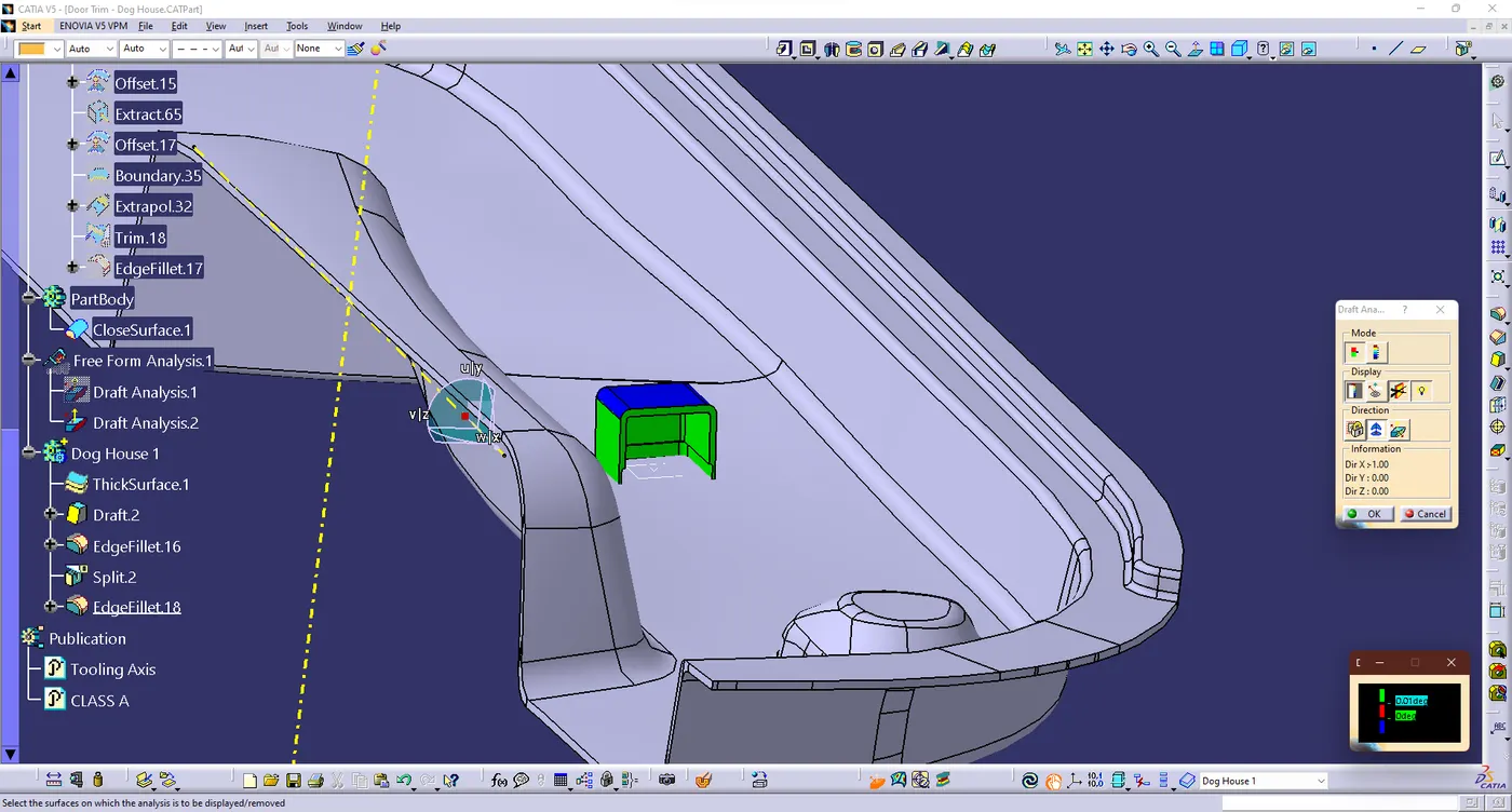
- DRAFT ANALYSIS FOR DOG HOUSE 1:
- In Plastic Design, the draft analysis or angle that is considered in the OEMs is 3 degree.
- Same thing were do follow for the draft analysis on earlier and output mention below
- Then we got degree has 0.01 deg
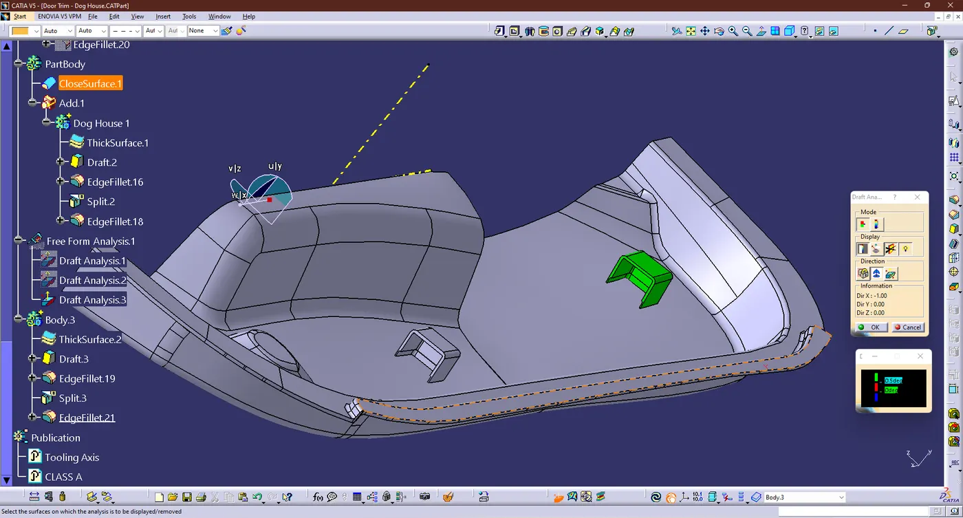
- DRAFT ANALYSIS FOR DOG HOUSE 2:
- In Plastic Design, the draft analysis or angle that is considered in the OEMs is 3 degree.
- Same thing were do follow for the draft analysis on earlier and output mention below
- Then we got degree has 0.5 deg
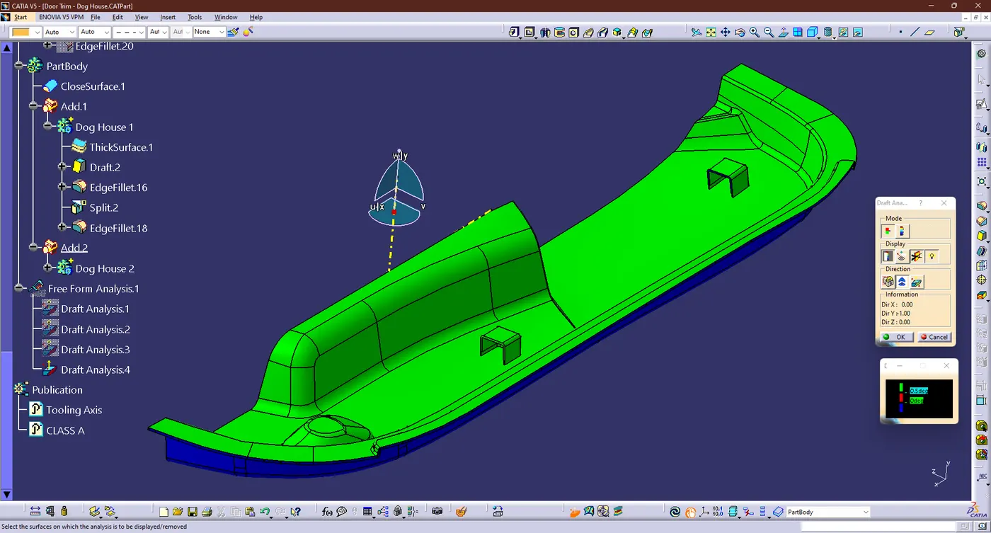
- DRAFT ANALYSIS FOR PARTBODY:
- In Plastic Design, the draft analysis or angle that is considered in the OEMs is 3 degree.
- Same thing were do follow for the draft analysis on earlier and output mention below
- Then we got degree has 0.5 deg
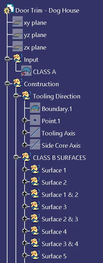
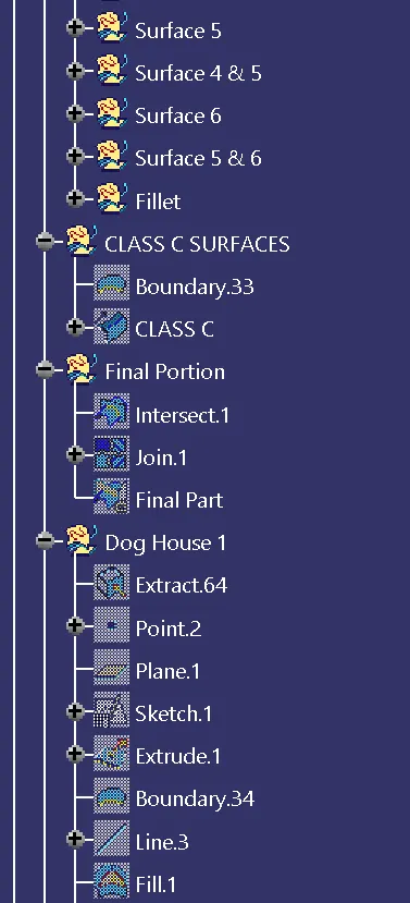
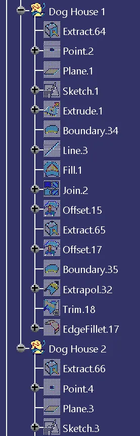
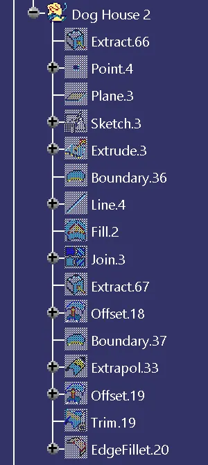
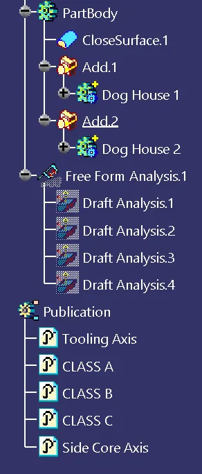
- TREE STRUCTURE:
- FILES:
- The output file were mention pn browse option in the name of the "Week 10 challenges 2 (Dog House).zip" and also output images were uploaded in the same folder.