Week 10 - Challenge 2- Attachment Feature Creation (Dog House)
Door trim is the part that is fitted to the inner side of the door. The lower portion of it contains the speaker sink where the speaker would sit at the time of assembly process in the industry. It is made of plastic and is produced by injection molding process. So it has to be created carefully in order to avoid any asthetic error on the surface which would spoil the overall look of the finished part.
*) There are other mounting points on other regions of the door trim for other features. The most common error is the sink mark that occurs due to designing the part not according to the guidelines.
*) Sink marks are the depressions or craters that develop at thicker areas of prototype which shrinkage occurs on inner protion of the finished product.
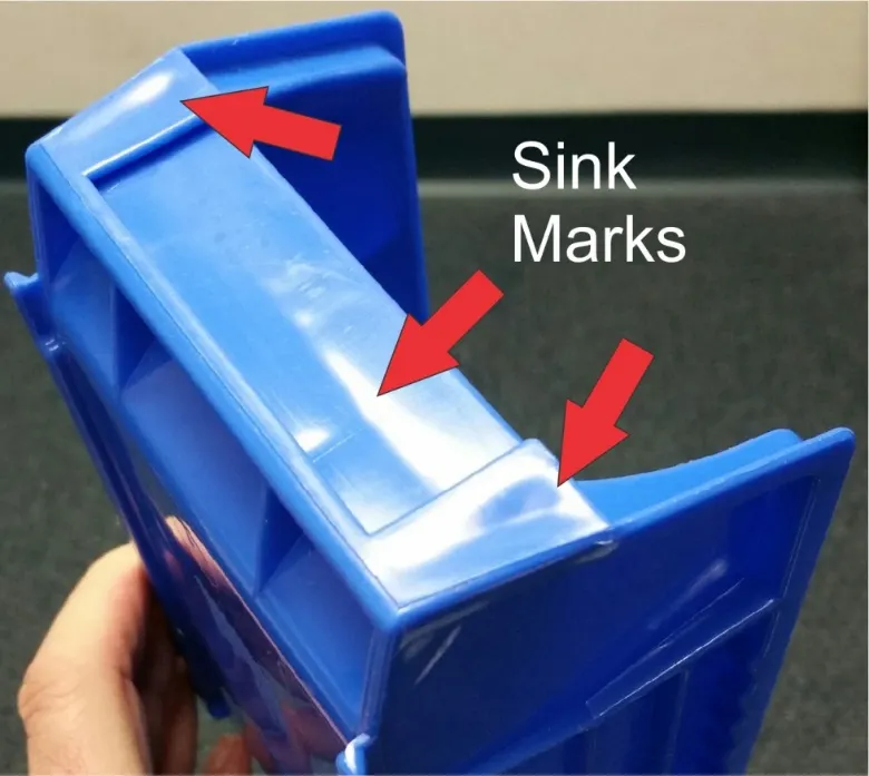
Causes
1) Insufficient cooling time.
2) Inadequate cavity pressure
3) Varying part thickness
Remedies
1) Give enough cooling time.
2) reduce variation in the thickness.
*) Dog house is an engineering feature created on B surface of plastic parts to avoid sink marks that are shown above. It is also given to avoid adaptation of large screw boss height which is liable to break easily under stress developed at the time of movement of the vehicle. So if a region require a screw boss of longer length then a dog house is created first of a certain height and on the top of the same, screw boss is created. It is subjected to draft analysis in order to prevent the part from getting damaged at the time of ejection.
DESIGN METHODOLOGY
*) A class of the door trim was already available. With the reference of class A, class B and C was created initially.
*) The quality of the class A surface was checked first by creating the boundaries. The boundary was continous and neat so the quality was considered good for further processes.
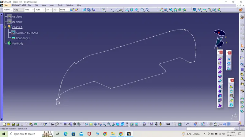
*) The next step was to create the tooling axis and for that the part was observed in different views.
FRONT VIEW
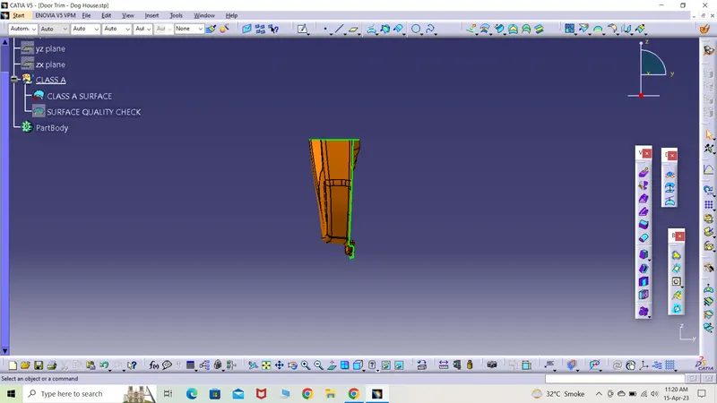
BOTTOM VIEW
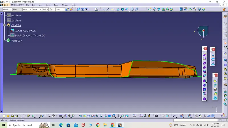
SIDE VIEW
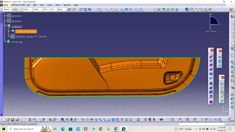
*) It was observed that the maximum surface area is visible in side view so the the region from the surface in the same view would be considered for creating the tooling direction.
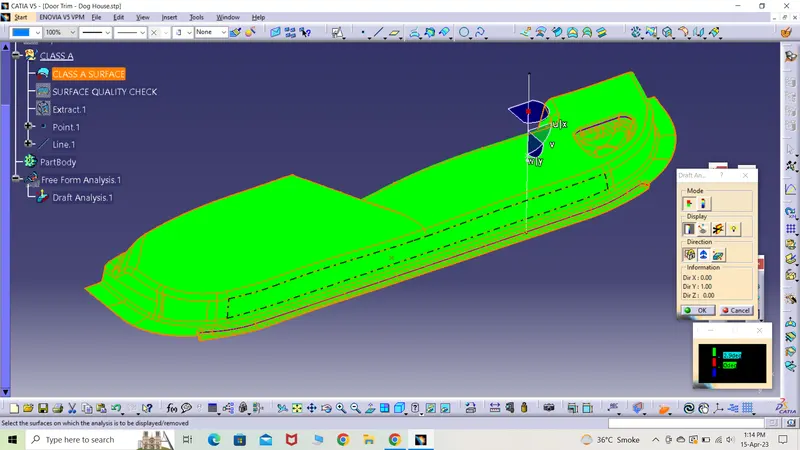
*) The tooling axis was drawn by three methods. The first one was created by creating a line by selecting the already created point. Then selecting the axis as y-axis the tooling line was created and the draft analysis was carried out.
POINT DIRECTION
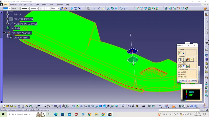
*) The same surface was considered and the flat face was extracted. A point was selected to create a line and it was created normal to the surface by selecting the alreadt extracted surface. Draft analysis was done and is shown below.
NORMAL TO SURFACE
*) The last method to create the tooling axis was bisecting line. The intersect of the surface was taken with reference to a plane. The two straight lines on either side of the surface was recreated with two lines each.
BISECTING LINES
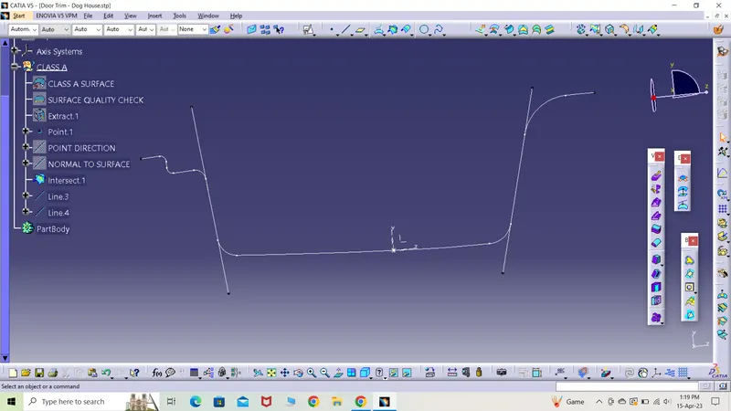
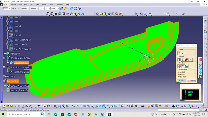
*) A bisecting line was created considering the two lines created earlier. The centre line was treated as the main tooling axis and draft analysis was done.
*) This tooling axis was considered the best one as least portion of the surface failed in the draft test and the reason was irregularly created class A surface. To remove these errors, class A surface would have to be recreated by the class A creators. This is the feedback given to the same team in order to correct the error.
Creation of the class B surface
*) The given class A surface was offsetted by 2.5mm towards inside. This is actually the thickness of the part.
*) The offsetted surface had so many open patches with no material in between so those had to be recreated.
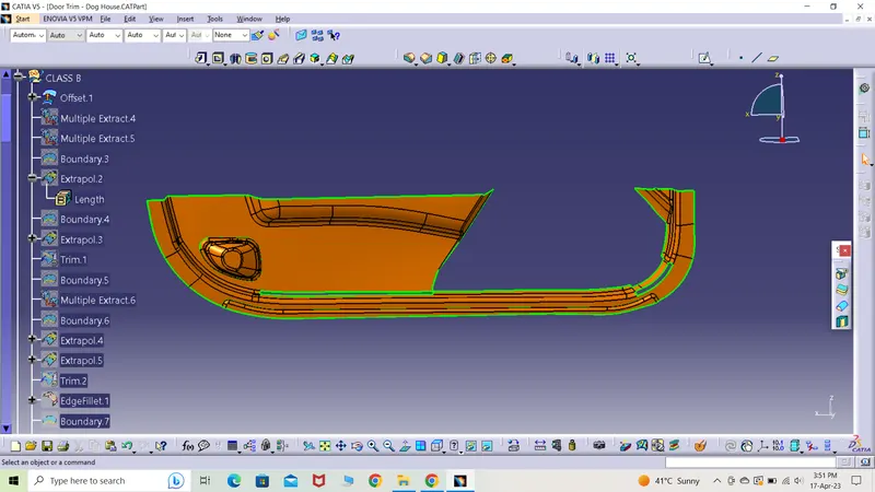
*) The bottom region was repaired first by extracting the particular regions with class B and then extrapolating the ends and later by trimming the intersecting surfaces.
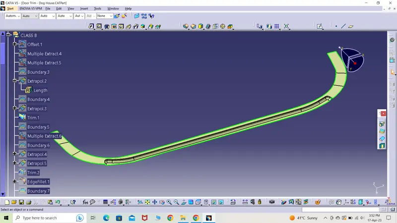
*) In the same manner, the adjacent region to the above surface was also created and necessary edge fillet of 7mm radius was given.
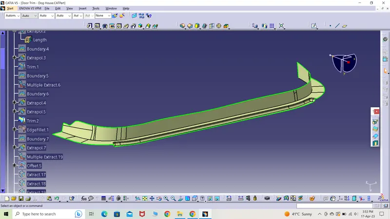
*) The toughest region to repair was the centre portion in which some regions were untrimmed and extrapolated and other were extracted, offsetted and later trimmed all of them together to get the centre region.
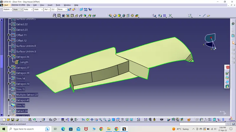
*) By using the first region with the latter region, both the surfaces were trimmed and filleted to get the surface. It was a complex task to execute.
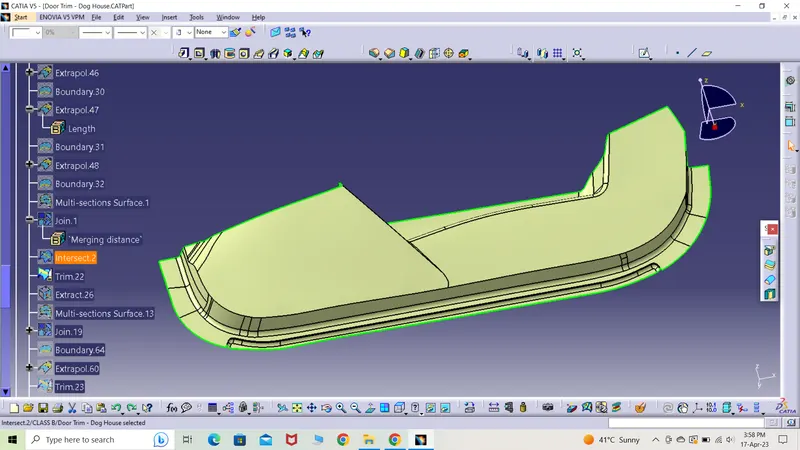
*) The speaker sink was left to join with the main B surface but it had a gap so it was repaired by removing that particular edge and later extrapolated it to exceed B surface.
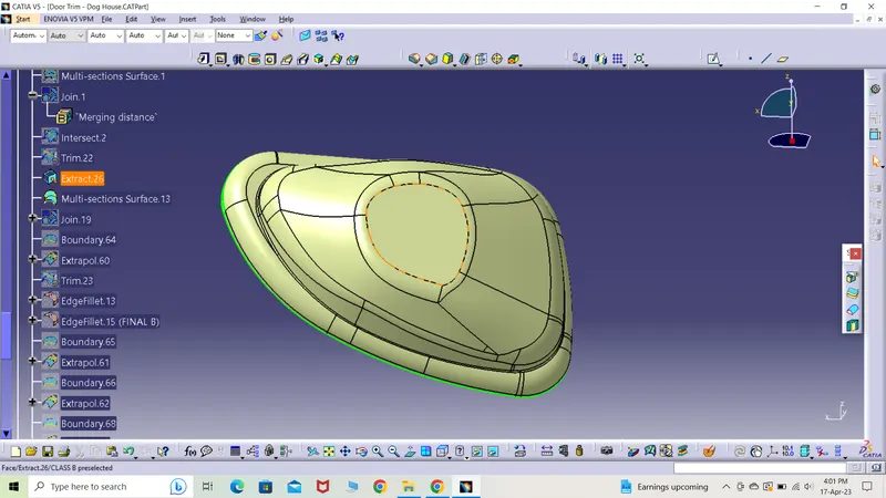
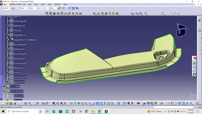
*) The below s.s is the final class B surface with extrapolated ends.
Class C surface creation
*) The class C surface is simply the wall of the part.
*) Several boundaries were created which were then used to extrapolate or sweep according to the desired surface requirement.
*) The different edges that were extrapolated were joined and trimmed to form the final class C surface.
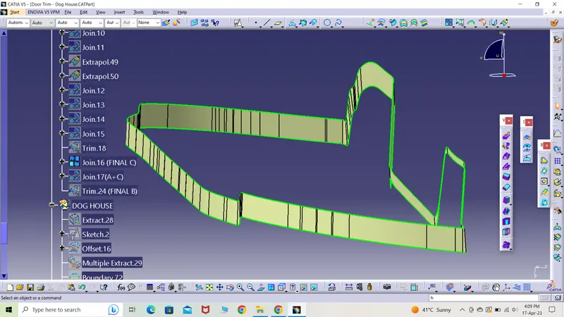
*) Class C and class surface were joined together to form a single surface A+C surface.
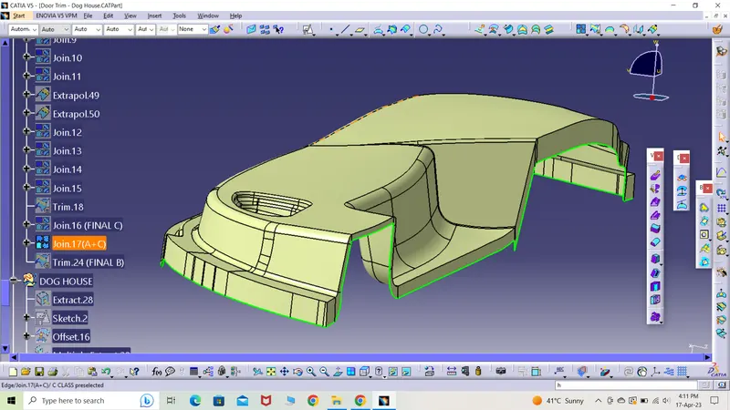
*) Surface A+B were then tried to trim but there were some gaps that didn't allow the process to complete.
*) The intersection of the two specified surfaces were taken and the blacks dots indicated the regions with gaps.
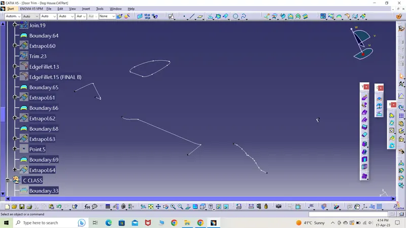
*) The gaps were filled by simply creating the boundary at that particular region and then extrapolated it.
*) In the end, the trim ran and the final hollow part to mold was created.
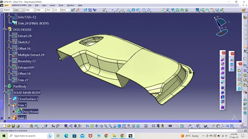
*) Catia was switched to part body mode where the above created hollow part was converted into a solid body by selecting close body command. The solid door trim part was obtained.
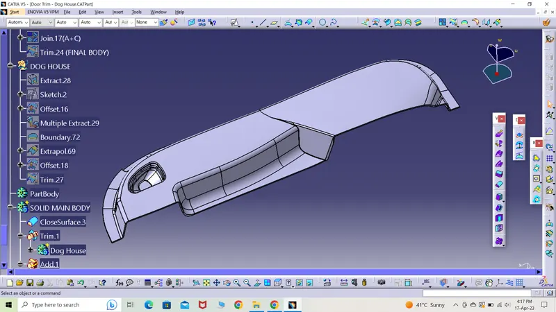
Dog house creation
*) The last task was to create the dog house.
*) Dog house would also be checked by draft analysis as it would require a side core to produce such a complex part.
*) To begin with, the surface on which dog house would be created was extracted and it was not needed to trim it as dog house was to be created away from that empty patch of speaker assembly.
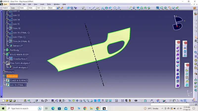
*) An iso-constraint sketch was created as per the safe dimension criteria in generative shape design mode.
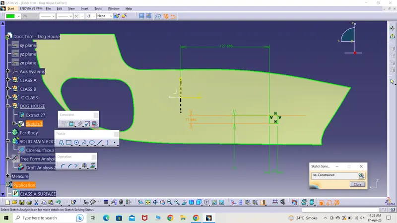
*) The sketch was padded to form a 3D model in part design mode. It was created considering the main draft tooling axis.
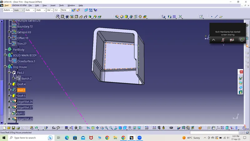
*) The two sides were drafted and shelled accordingly.
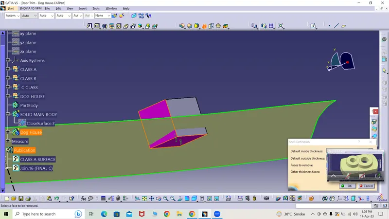
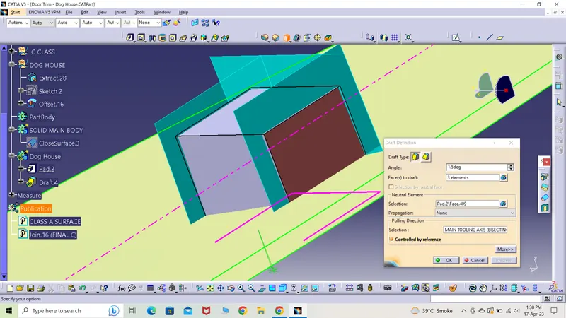
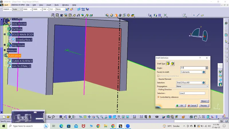
*) The edges were filleted with 3mm on outside and 1mm on the inside.
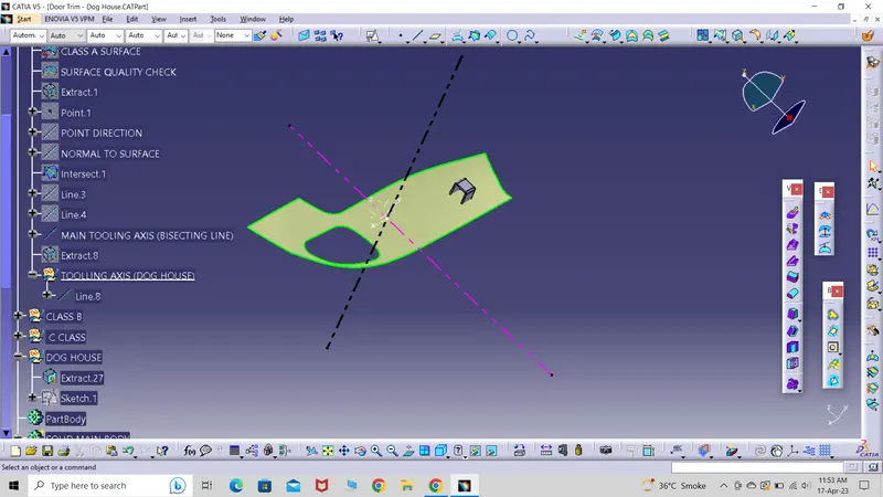
*) As per the safe design guidance, the changes were made.
*) The offset of the sides of (base of dog house thickness is 0.4*2.5mm) i.e. 1 mm were taken as reference to split the part from the bottom.
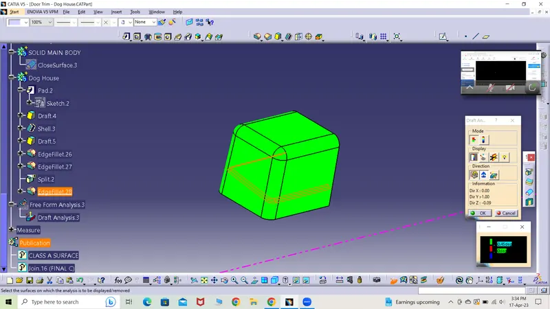
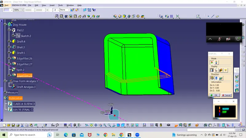
*) A seperate tooling axis by the name side core axis was created by using the same point but the direction was changed to x direction. The same axis was used whenever the drafting was carried on doghouse on the inside region.
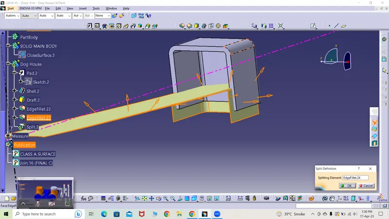
*) All the sharp edges were filleted to 0.5mm radius and the final dog house was created.
*) Draft analysis was done using the side core tooling axis and both the regions passed the test.
*) The second dog house was created by pasting special to the part file and later traslating the same using the coordinate figures.
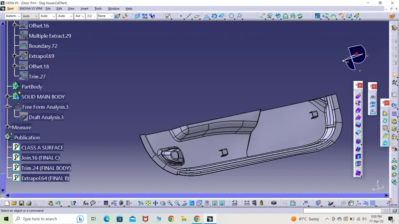
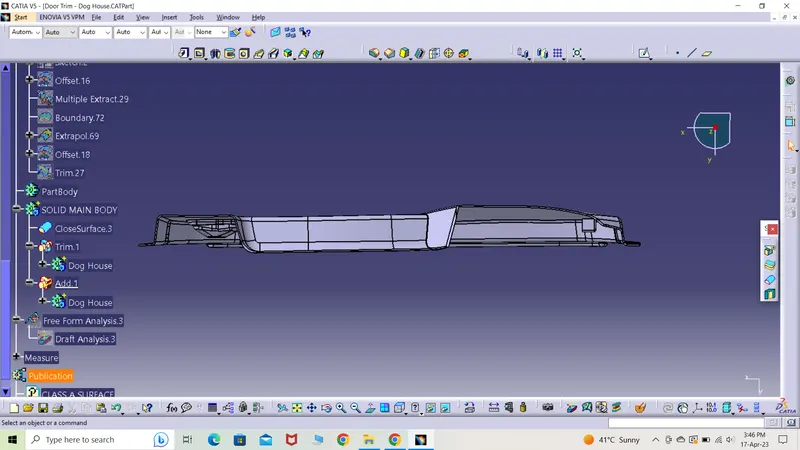
*) Both the dog houses were uni-trimmed with unwanted surfaces removed and the finished part was obtained and is shown in different views.
ISOMETRIC VIEW
SIDE VIEW

FRONT VIEW
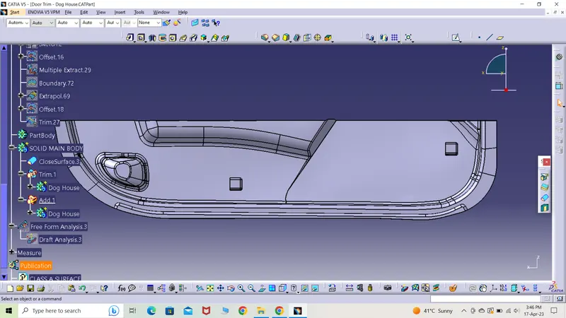
TOP VIEW
->) For a detail dive into the model, the catia part file of the same part has been attached below.