Week 10 Challenge
Q 1)What all checks need to be followed in design of well foundation regarding the stability and the design. List out all the necessary clauses from IRC codes applicable.
Ans :
The following two methods for stability analysis of well foundations are discussed below:
1. Terzaghi’s method.
2. IRC method.
1. Terzaghi’s Method:
Terzaghi’s analysis for rigid bulkheads assumes that the bulkhead is light and there is no friction at the base and the sides. The lateral pressure is computed using Rankine’s theory. This method can be applied for stability analysis of well foundations, neglecting the moments due to friction at the base and the sides. Hence, Terzaghi’s analysis, when applied to well foundations gives conservative estimates.
When a rigid well, embedded in sand, moves parallel to its original position, the soil on the front side of the well will exert passive resistance and the soil on the rear side will exert active pressure. Assuming that the shear strength of the soil is fully mobilized simultaneously on the front and rear sides, the soil on the front side will be in Rankine’s passive state and that on rear side in Rankine’s active state. The net pressure at any depth h acting on the well is given by –
p = γh(Kp – Ka) …(21.10)
where p is the net pressure at any depth h, γ is the density of the soil, Kp is Rankine’s coefficient of passive earth pressure, and Ka is Rankine’s coefficient of active earth pressure.
2. IRC Method:
The lateral stability of a well foundation is provided by passive resistance of the soil on its sides and base. The resistance developed at the working loads is different from that at the ultimate load.
IRC – 45-1972 recommends the following two methods for stability analysis of well foundations:
i. Elastic theory to estimate the soil pressure on the sides and at the base under working loads.
ii. The ultimate soil resistance method to determine the factor of safety against shear failure.
The IRC methods are applicable only if the depth of embedment is at least equal to 0.5 times the width of the foundation in the direction of lateral forces.
The methods are given for the design of well foundations resting on non-cohesive soil and surrounded by the same soil below the maximum scour level. The moment distribution between the base and the sides of the well continuously change with an increase in the deformation of the soil. The Elastic theory gives the soil pressure at the side and base under design loads. The factor of safety against failure is determined by considering the ultimate soil resistance method.
i. Elastic Theory:
The Elastic theory, used to determine soil pressure below the base and on the sides, is based on the following assumptions:
a. The soil surrounding the well and below the base is perfectly elastic, homogeneous and follows Hooke’s law.
b. The unit soil reaction (p) increases linearly with an increase in lateral deflection (z). Hence, p = kHz, where kH is the coefficient of horizontal sub-grade reaction at the base.
c. The coefficient of horizontal sub-grade reaction (kH) increases linearly with depth for cohesionless soils.
d. The well is assumed to be a rigid body, subjected to an external unidirectional horizontal force H and moment Mo at the scour level.
The total horizontal soil reaction acting on the sides of the well (P) is given by –
P = 2mKθIv/D …(21.22)
where m = KH/K is the ratio of the horizontal to the vertical coefficient of sub-grade reactions at the base, K is the coefficient of vertical sub-grade reaction at the base, θ is the angular rotation of the well with the vertical, Iv is the moment of inertia about the horizontal axis passing through the center of gravity (C.G.) of the projected area in elevation of the soil mass offering resistance = LD3/12, L is the projected width of the soil mass offering resistance multiplied by shape factor “S,” D is the depth of the well below the scour level, and S = shape factor = 0.9 for circular wells. The moment about the base level, M is given by –
Mp = mKθIv …(21.23)
where Mp is the moment of P about the base.
The maximum and minimum pressures at the base of the well are given by –
where W is the total weight of the well, µ is the coefficient of friction between the sides of the well and the surrounding soil, P is the total horizontal soil reaction as given by Eq. (21.22), A is the area of the base of the well, M is the total applied external moment at the base = Mo + HD, Mo is the moment of external forces at the scour level, B is the width of the base of the well parallel to the direction of the external horizontal force –
I = IB +mIv (1 + 2µ’α) …(21.26)
and IB is the moment of inertia of the base about an axis passing through the C.G. and perpendicular to the horizontal resultant force. For rectangular wells –
α = B/2D …(21.27)
For circular wells –
Conditions of stability for well foundations based on elastic theory are as follows:
a. The maximum soil reaction (σx) from the sides shall not exceed the maximum passive pressure at any depth.
b. The maximum soil pressure at the base (σ1) shall not exceed allowable pressure on soil.
c. The minimum soil pressure at the base (σ3) shall not be negative, that is, no tension shall be allowed to develop at any point in the soil below the base.
The following is the procedure for stability analysis of well foundations as per the elastic theory method of IRC:
a. Determine the grip length, applied loads, and moment.
b. Calculate the moment of inertia of the base of the well foundation about the centroidal axis perpendicular to the direction of the resultant horizontal force by –
IB = (π/64) B4 …(21.32)
where B is the width of the well or the diameter of a circular well.
c. Determine the moment of inertia about the centroidal horizontal axis of the projected area in elevation of soil mass offering resistance
where Kh and Kv are coefficients of sub-grade reaction in the horizontal and vertical directions, respectively, L is the projected width of the well in contact with the soil that offers passive resistance multiplied by the shape factor, S, S = 0.9 for circular wells, S = 1 for square or rectangular wells, µ is the coefficient of friction between the sides of the well and the soil = tanδ ≈ tanɸ, and D is the depth of the well below the scour level.
d. Check that the point of rotation of the well lies at the base by ensuring that the frictional force at the base is adequate to restrain the movement of the well
e. Check that the soil on the sides of the well remains elastic. This can be ensured by keeping the slope of the pressure parabola at the top below the passive pressure line, that is
where Kp and Ka are Coulomb’s coefficients of passive and active earth pressure assuming
f. Check the base pressures ensuring that the maximum compressive pressure is less than the allowable bearing pressure and that the minimum pressure is not tensile.
where P is the total horizontal reaction from the sides and B is the width of the base of the well in the plane of bending.
ii. Ultimate Soil Resistance Method:
The safety against ultimate failure of well foundations is considered by the ultimate soil resistance method. The mode of failure of the soil mass under the application of transverse forces on a well foundation is shown in Fig. 21.9. The soil around the base of the well slides over a circular cylindrical path with center of rotation above the base. Failure has been observed to occur at about 3° of the rotation of the well in the case of cohesionless soil.
The following are the methods to ensure a minimum level of safety against failure:
a. The applied loads are increased by a load factor using the most critical of the following combinations
Where DL is the dead load, LL is the live load including braking force, etc., BF is the buoyancy force, Wc is the water current force, Ep is the earth pressure, WL is the wind force, and SL are the seismic forces.
The applied moment (M) is calculated by considering most critical combination of the above five load combinations.
b. The total resisting moment (Mr) is reduced by a strength factor to ensure safety against failure as
0.7 (Mr) M (21.45)
Mr = Mb + Ms + Mf (21.46)
where Mr is the total resisting moment offered by the soil, Mb is the base resisting moment, Ms is the side resisting moment, and Mf is the resisting moment due to friction on the front and back faces –
Mb = QWB tanɸ …(21.47)
where Q is a constant given by Table 21.5 for rectangular wells, W is the total vertical load, B is the width or diameter of rectangular or circular wells, and <p is the angle of internal friction of the soil.
Also, we have
Ms = 0.1 γD3 (Kp – Ka)L …(21.48)
where L is the width of the well.
Q 2) What are the limits in ULS and SLS for design of a RCC component. Define the limit states and the factors in it as per IRC 112.
Also mention shear checks . what is the difference in shear with/without reinforcement?
Ans :
Ultimate limit state (ULS)
A clear distinction is made between the ultimate state (US) and the ultimate limit state (ULS). The US is a physical situation that involves either excessive deformations leading and approaching collapse of the component under consideration or the structure as a whole, as relevant, or deformations exceeding pre-agreed values. It involves, of course, considerable inelastic (plastic) behavior of the structural scheme and residual deformations. In contrast, the ULS is not a physical situation but rather an agreed computational condition that must be fulfilled, among other additional criteria, in order to comply with the engineering demands for strength and stability under design loads. A structure is deemed to satisfy the ultimate limit state criterion if all factored bending, shear and tensile or compressive stresses are below the factored resistances calculated for the section under consideration. The factored stresses referred to are found by applying Magnification Factors to the loads on the section. Reduction Factors are applied to determine the various factored resistances of the section.
Serviceability limit state (SLS)
In addition to the ULS check mentioned above, a Service Limit State (SLS) computational check must be performed. To satisfy the serviceability limit state criterion, a structure must remain functional for its intended use subject to routine (everyday) loading, and as such the structure must not cause occupant discomfort under routine conditions.
As for the ULS, the SLS is not a physical situation but rather a computational check. The aim is to prove that under the action of Characteristic design loads (un-factored), and/or whilst applying certain (un-factored) magnitudes of imposed deformations, settlements, or vibrations, or temperature gradients etc. the structural behavior complies with, and does not exceed, the SLS design criteria values, specified in the relevant standard in force. These criteria involve various stress limits, deformation limits (deflections, rotations and curvature), flexibility (or rigidity) limits, dynamic behavior limits, as well as crack control requirements (crack width) and other arrangements concerned with the durability of the structure and its level of everyday service level and human comfort achieved, and its abilities to fulfill its everyday functions. In view of non-structural issues it might also involve limits applied to acoustics and heat transmission that might also affect the structural design.
Q 3)How to check steining thickness and its steel.What will be the change in PCC and RCC steining.
Ans-
- Steining thickness shall be less than 500mm and satify the following
h = Kd√l
k = Minimum thickness of steining in m
d = External dia of circular well
l = Depth of wells in m
- Minimum steining steel shall not be less than 0.2 percent of acutal cross sectional area.
- Inner face 0.06 percent outer face 0.14 percent
- Transverse shall not be less than 0.04 percent
- Stresses in steining shall be checked at critical points where tensile/compressive stresses are likely to be maximum.
Q 4) How the spacing of pile is determined in 6 pile system . describe the bulb theory with neat diagrams showing the stress distributions.
Ans :
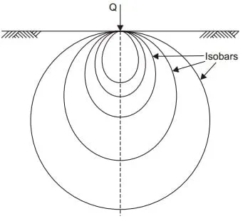
Stress Isobar or Pressure Bulb Concept
An isobar or pressure bulb is a stress contour or a line which connects all points below the ground surface at which the vertical pressure is the same. In fact, an isobar is a spatial curved surface and resembles a bulb in shape; this is because the vertical pressure at all points in a horizontal plane at equal radial distances from the load is the same. Thus, the stress isobar is also called the ‘bulb of pressure’ or simply the ‘pressure bulb’. The vertical pressure at each point on the pressure bulb is the same. Pressure at points inside the bulb are greater than that at a point on the surface of the bulb; and pressures at points outside the bulb are smaller than that value. Any number of pressure bulbs may be drawn for any applied load, since each one corresponds to an arbitrarily chosen value of stress. A system of isobars indicates the decrease in stress intensity from the inner to the outer ones and reminds one of an ‘Onion bulb’. Hence the term ‘pressure bulb’. An isobar diagram, consisting of a system of isobars appears somewhat as shown in Fig. 1 and Fig. 2.
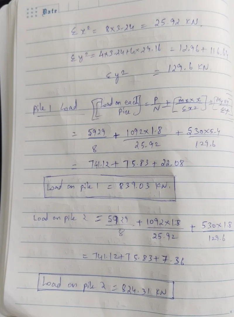
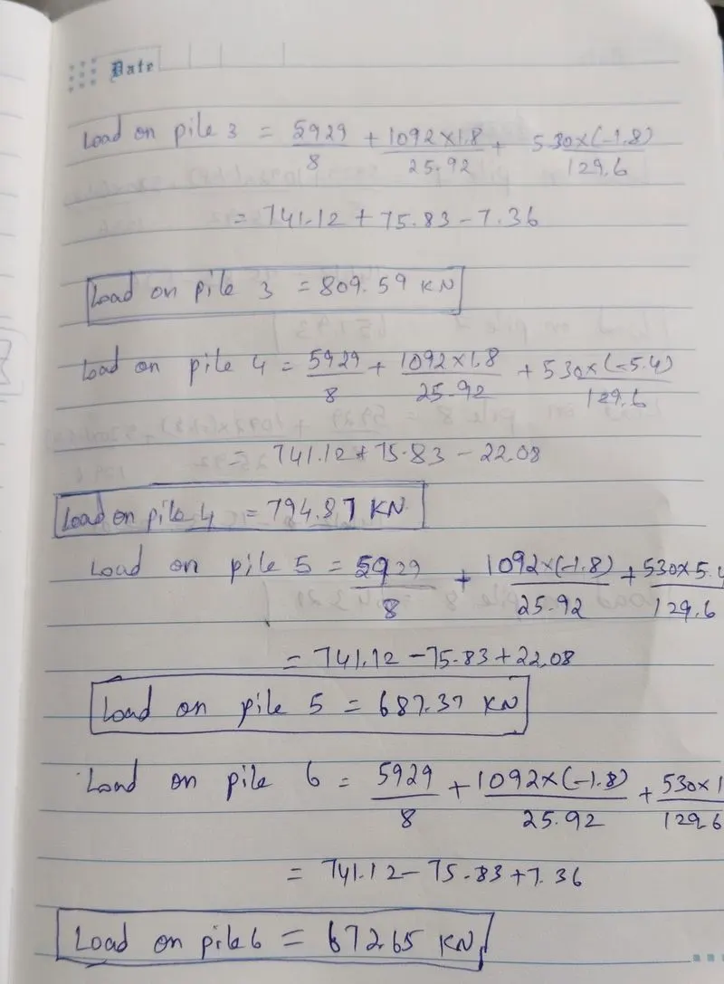
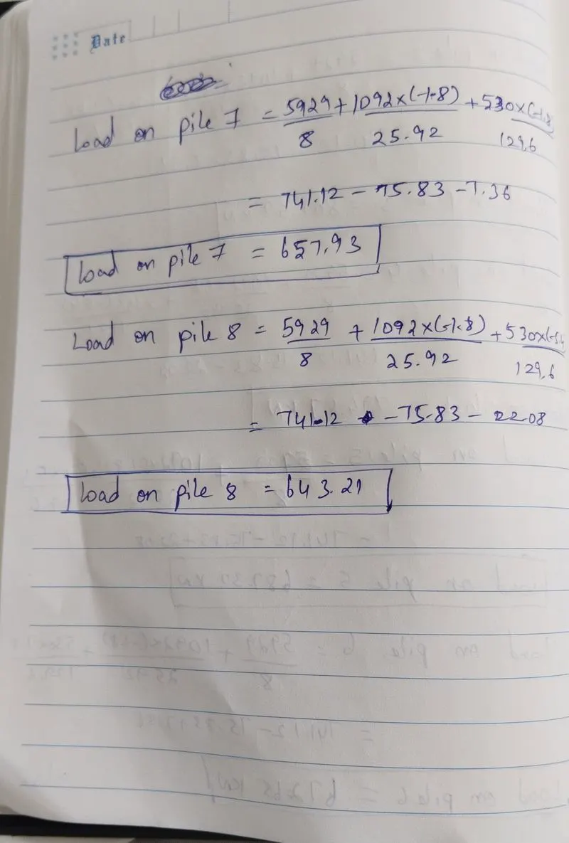
- Total vertical reaction (P) = 5929 kN
- Total moment about L-L axis (ML) = 1092 kN.m
- A total moment about the T-T axis (MT) = 530 kN.m
- Total horizontal force along L-L axis (HL) = 83kN
- Total horizontal force along T-T axis (HT) = 172 kN
Assumption -
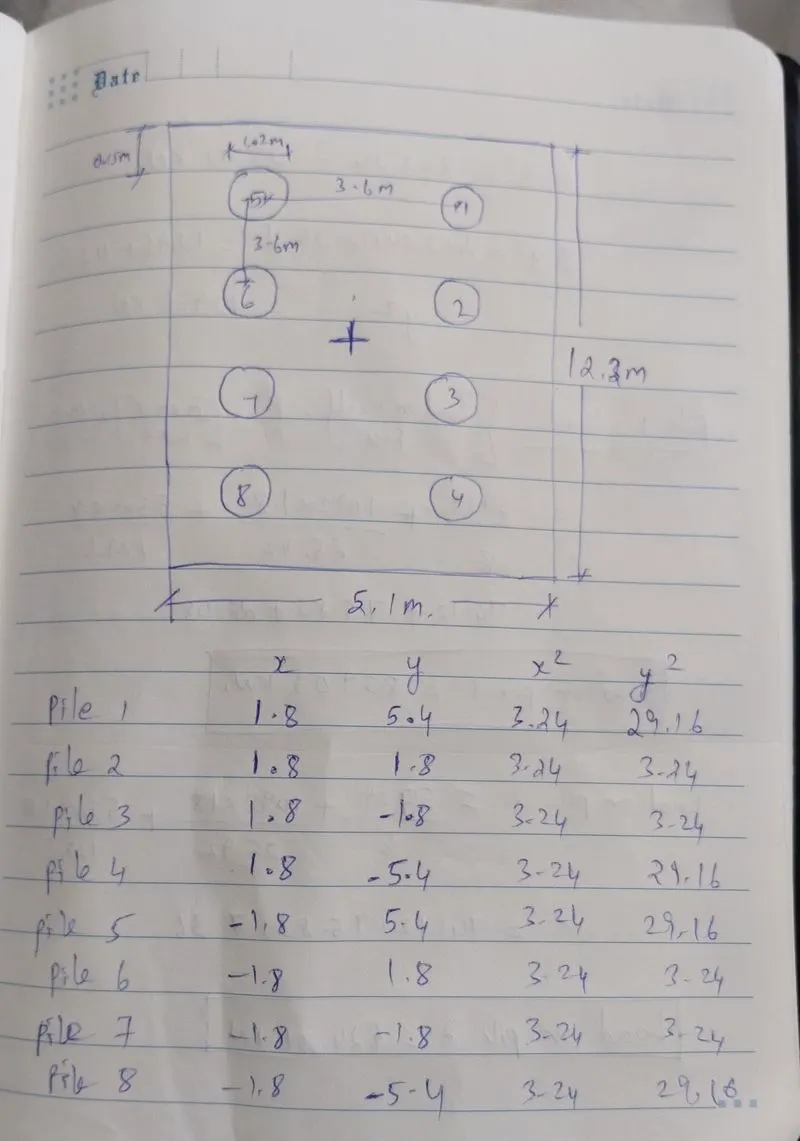
- Total no of piles (n) = 8 Nos.
- Dia of Pile = 1.2 M
- Distance between the p = 3.6 in both directions.
- Offset on both ends = 150 mm.