Week 10 Challenge
Q1) Purlin & Girts number determination problem
Calculate total number of purlins and girts required for the building with following inputs
Rafter span = 50 m
Bay spacing = 8 m
Roof slope = 1 in 10
Height of column = 12 m
Brick wall height = 2 m
Purlin spacing = 1.2 m
Girt spacing = 1.5 m
Ans:
Aim :A pipe carrying LNG rests on the shoe having vertical force of 125KN.Friction load on the axis and friction force are required to be determined if there is TEFLON pad between shoe and pipe support.
Procedure:
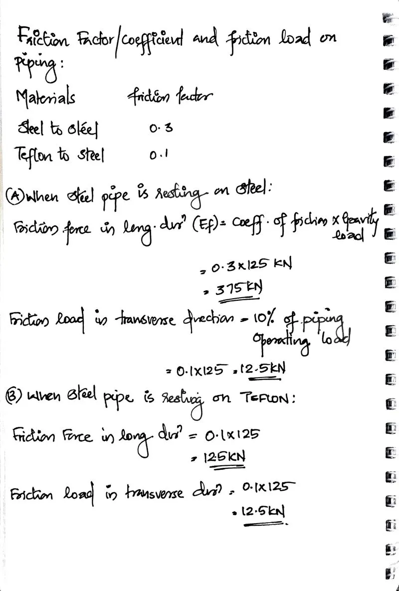
Result : Friction load and transverse direction are 37.5KN & 12.5 KN respectively
When pipe is resting on steel and these friction forces are 12.5KN & 12.5KN respectively when pipe is resting on Teflon
Q2)Taper the beam according to BMD envelope
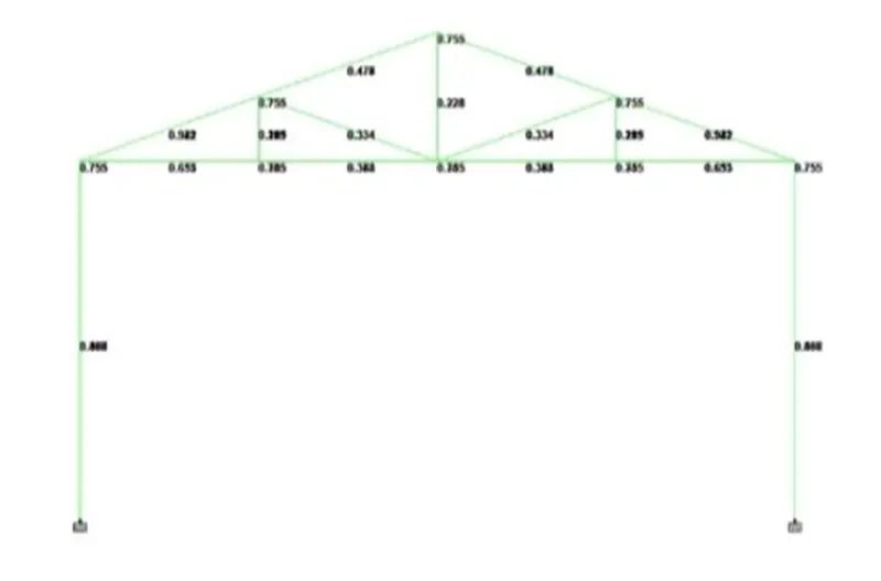
For the STAAD file attached. For given loading taper the beam for the BMD envelope and check utility ratio within limit. (Design Parameter is already applied)
Aim :To taper the beam according to B.M.D diagram and check the utility ratio
Procedure:
For the given cases :
1)Spring support :Permit the pipe to move in the vertical direction.
2)Rigid support :Allow small angular displacement and thermal movement.
3)Stop support : Restrained the movement of pipe in axit al direction but allows the pipe movement in lateral direction.
4)Semi anchor support: Restrict the pipe to move in axial as well as transverse direction
5)Guid support: Restrained the lateral movement in 2 direction therefore also limits the rotational movement of pipe but permit axial movement of pipe.
6)Anchor support:It does not permit the pipe to move in any direction thus movement in all 6 degree of freedom is restricted.
Procedure:
Fig 1:
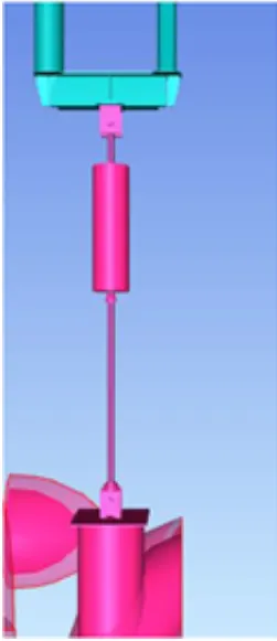
Type of support: Spring support
Fig 2:
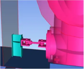
Rigid support
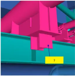
Stop support
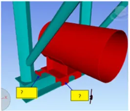
Semi Anchor support
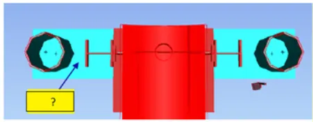
Anchor support
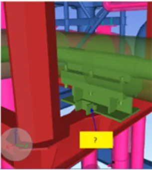
Result: Type of support for all figures has been identified.
3. Determining Wind load for certain category and condition as per IS 875 Part 3 :2015
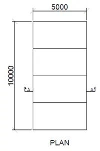
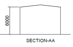
An Industrial building of plan dimension 10m x 5m to be constructed (as in Figure below). Building is situated in Chennai. Find the wind pressure on the wall of the building. Assume wall opening as 15 %. Bay spacing = 2.5m.
Ans:
Aim :To determine wind load for certain category and condition as per IS 875 part 3:2015
Procedure:
Step 1: Define nodes and beams and create model
Step2:Go to transition and apply bay spacing and click ok
Step 3:Go to properties and define selection and choose tapered section and put all data.
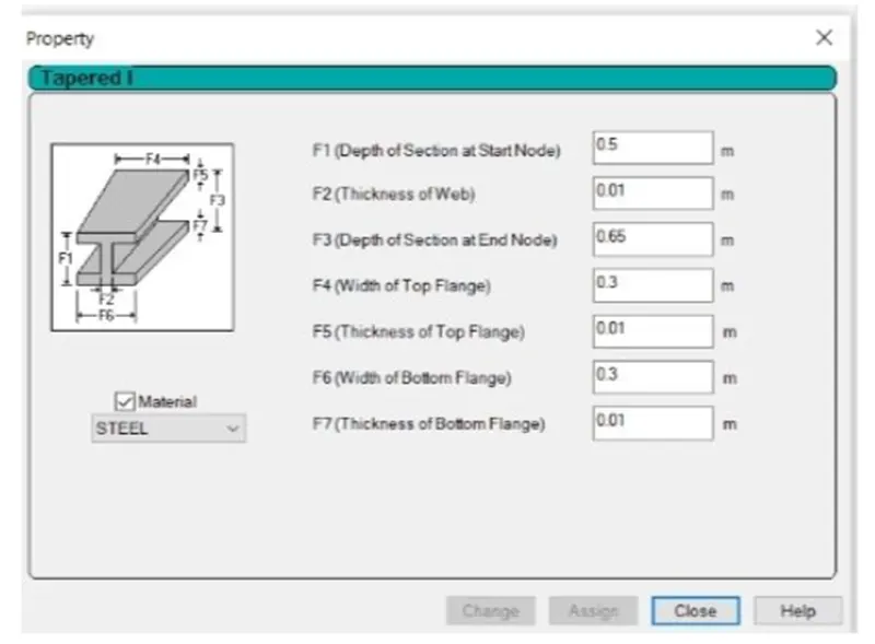
Go to support and create support and apply ok.
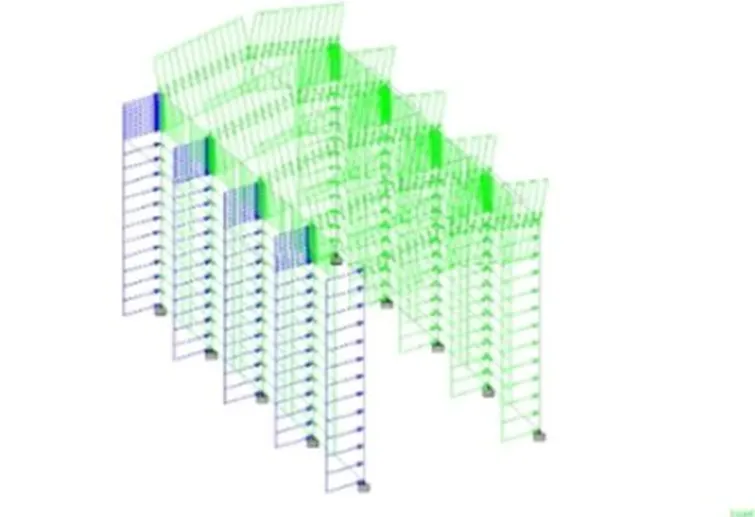
Go to loading add dead load,live load and wind load and go to case details add and dssign load to structure.
dead load=5KN/M^2
live load=5KN/M^2
Wind load as per IS 875 part 3
Location :Chennai
Basic wind speed =50M/s
Probabilty factor,K=1
Terrain roughness and height factor =K2=1.15
Topography factor = K3=1
Importance factor for cyclonic region=K4=1.15
Design wind speed =Vb*K1*K2*K3*K4
= 50*1*1*1.15
Wind pressure = 1.984KM/sqm =0.6*57.5^2
Wind directionality factor ,Kd=1
Area averaging factor Ka=0.83
Combination factor Kc=0.9
Design wind pressure =1.984*1*0.83*.9=8.89Kn/m
Internal pressure coefficient =+/-0.5
External pressure coefficient =
0 degree EF -0.9
0 degree GH -0.4
90 degree EG – 0.8
90 Degree FH -0.4
4. Find support reaction for given load. Static check problem
Mono sloped structure (20 degree) of width 10 m & length 30 m with bay spacing of 6 m having no wall sheeting (fully open all around) has following loads. Model the structure in STAAD. Apply Dead load, Live Load & Wind load on the structure and find the support reaction. Also perform static check if the total load applied on the structure is captured in support reaction for each load case.
Self Weight factor – 1.1
Roof Sheet loading = 0.5 kN/m2
Purlin load = 6 kN/m2
Live Load on Roof = 1.5 kN/m2
Wind Load on rafter (Pressure) = 2 kN/m2
Ans:
Aim:
Open new file and create nodes and beams
Mid height of roof =5tan20=1.81m
Go to translation and apply bay spacing and click ok
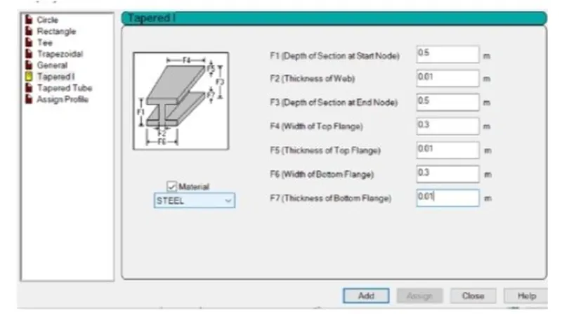
Go to properties and define section and tapered section choose and put all data.
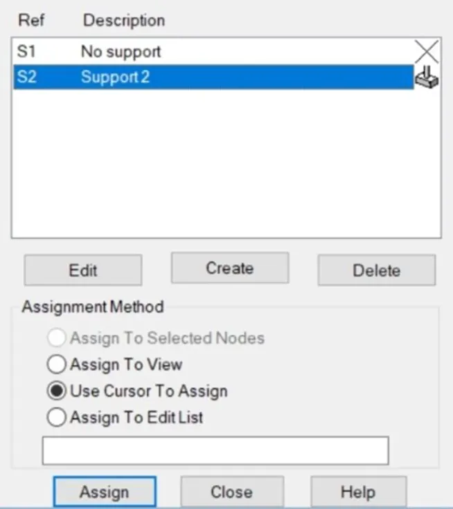
Go to support and create support.
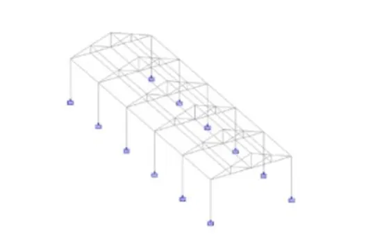
Go to loading and add dead load,live load and wind load and go to casedetails and add and assign load to the structure
Roof sheeting load =0.5Kn/sqm
Purlin load =6 KN/M^2
dead load=6+0.5=6.5KN/sqm =6.5*6=39KN/m
live load=1.5KN/m =1.5*6 = 9KN/m
wind load= 2*6=12KN/m
Go to run analysis and choose IS 800LSD and add design parameters and run analysis ad check results