Week 10 - Challenge 1- Attachment Feature Creation (Ribs & Screw Boss)
Challenge 1 - Attachment Feature Creation (Ribs & Screw Boss)
OBJECTIVE: To create an attachment feature like a rib and screw boss on a plastic door handle component 3D Solid CATpart in CATIA from the given Class-A surface by meeting the requirements of the draft angle and the attachment feature guidelines.
MAIN PROJECT:
A) Door Handle Plastic Design:
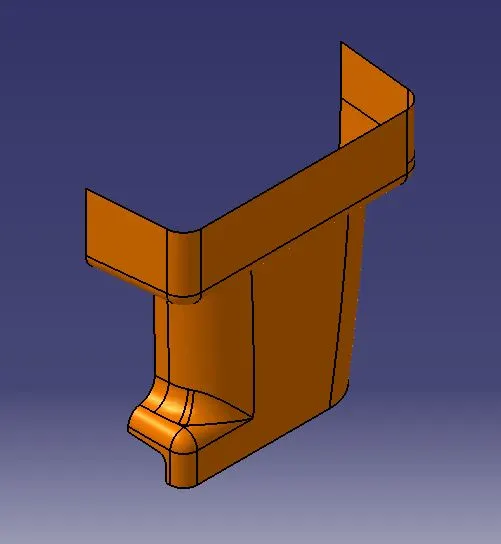
Given: Class-A Surface
This surface is crafted from conceptual sketches that originate as freehand drawings. Once the final sketch is completed, it is input into a computer where specialized software, such as Alias, is used to transform it into a detailed 3D surface.
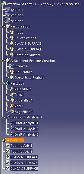
High-Level Tree-Structure of 3D CATPart:
Tooling Axis:
In moulding, the "tooling axis" denotes the specific orientation or direction in which the mould tool or cavity is constructed for opening and closing. Effective mould tooling is vital in the plastic injection moulding process, where molten plastic is injected into a mould cavity to yield a final plastic part.
Tooling Axis Creation:
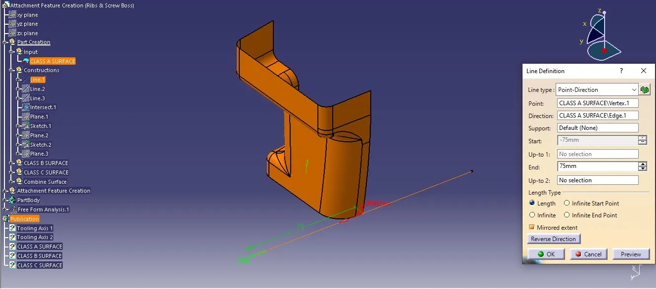
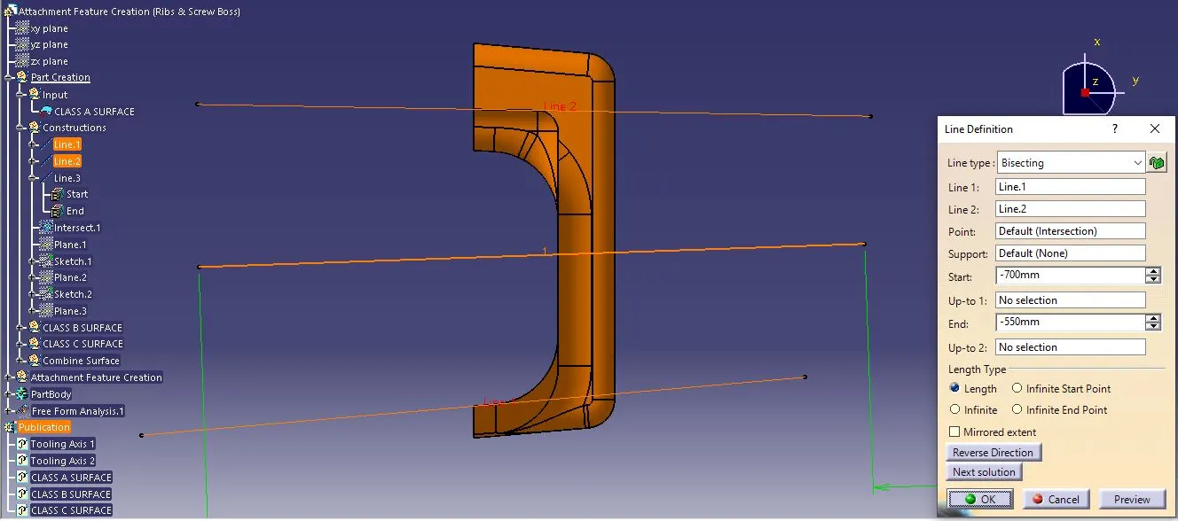
STEP-1: Construct a line using the line definition command on the bottom side edges of the Class-A Surface as shown below.
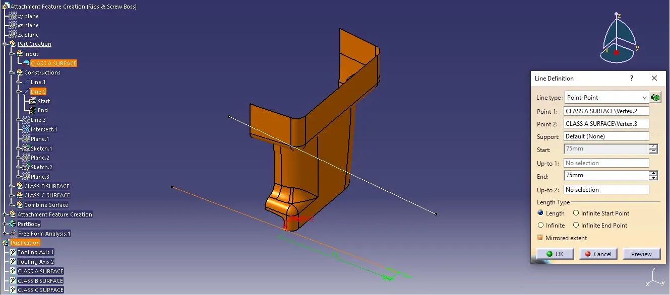
STEP-2: Bisecting Method
Construct a bisecting line using the line definition command by selecting lines 1 & 2 and consider it as tooling axis
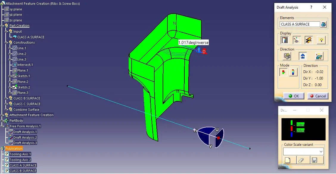
STEP-3: Class-A Surface Draft Analysis:
Before creating the part model, Class-A Surface draft analysis is important to check the difficulty of manufacturing.
Drafting possibilities based on various axes.
X-axis: Difficult and will increase the cost of manufacturing.
Y-axis: Cheap and easy way to produce the component.
Z-axis: Not possible to produce.
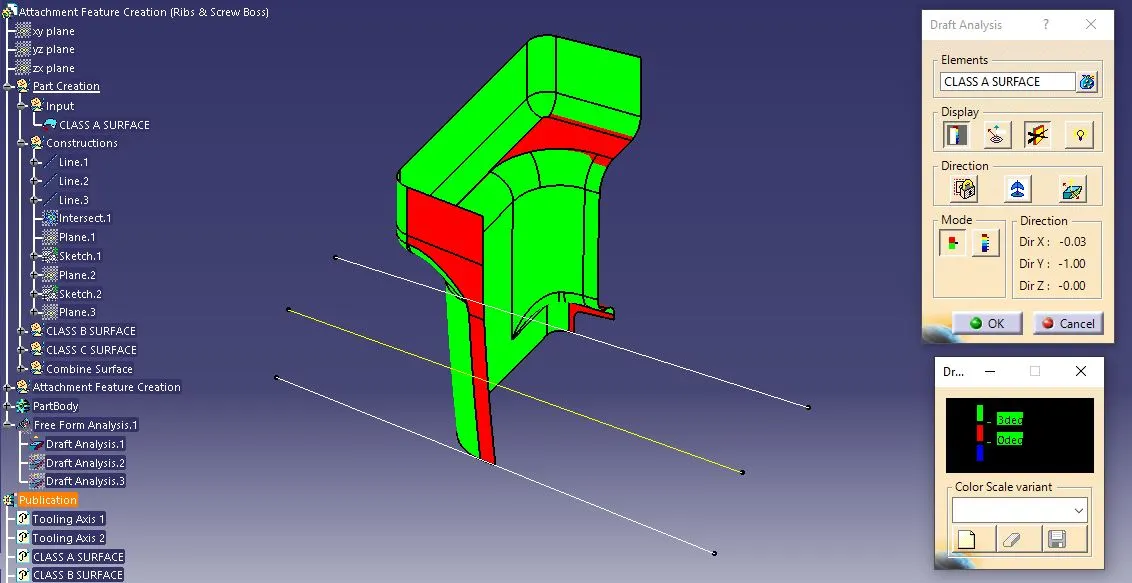
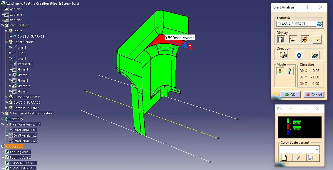
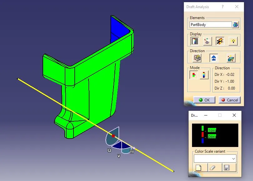
Here the Class-A Surface fails to clear the draft analysis at 3-deg draft angle, but it is better at a 1-deg draft angle as shown in the below image.
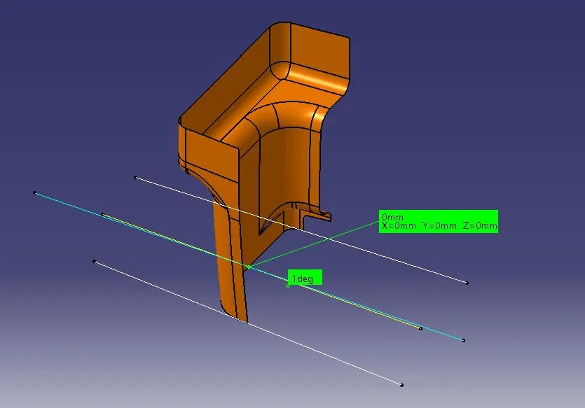
STEP-4: Another tooling axis is built 1 degree apart from the previous one to achieve a 1-deg draft angle.
Class B Surface:
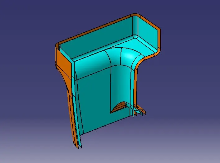
It is a reference surface that is created by the design engineer and it is a copy of the Class-A Surface that is at a distance equal to the thickness of the part.
Class-B Surface Creation:
STEP-1: A geometrical set of Switch Bezel Rest Surface was created under the Class B Surface.
STEP-2: Then offset the entire Class-A Surface by 3mm inwards and the missing surface is recreated by using the Multi-Sections Surface command.
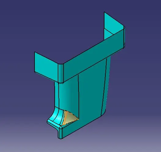
STEP-3: The boundary of the surface is taken and then extrapolate the surface by 5mm.
Class C Surface:
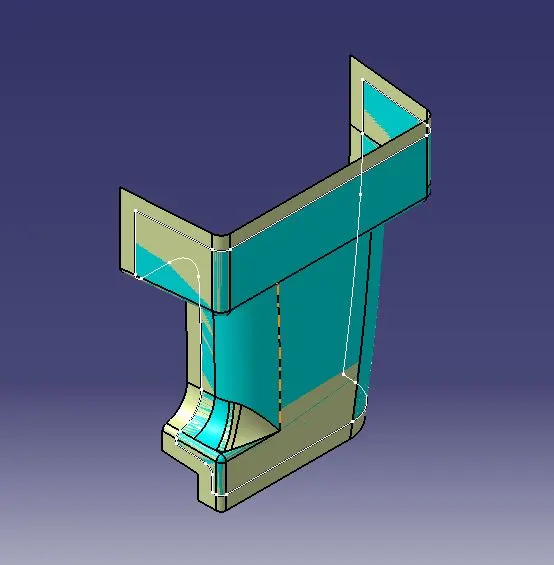
It is a reference surface that is created by the design engineer to connect Class-A and Class-B Surface also known as the side wall of the surface.
Class-C Surface Creation:
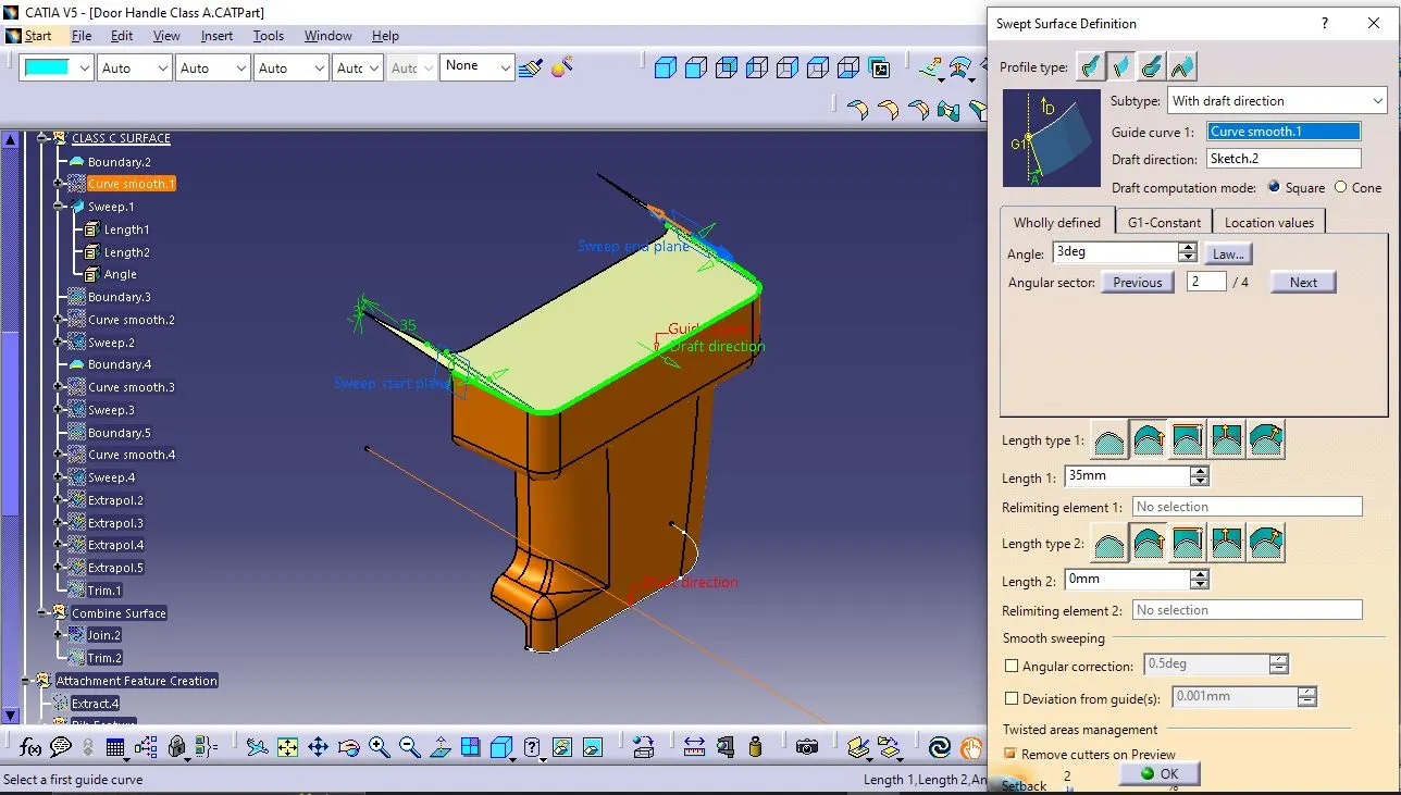
STEP-1: Construct a boundary on the Class-A Surface by limiting them to one side which is parallel to the tooling axis and then use the sweep command to construct the Class-C Surface with a draft angle of 3- deg.
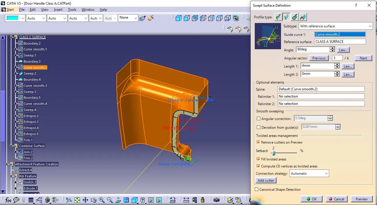
STEP-2: Construct another boundary on the Class-A Surface by limiting them to the next side which is perpendicular to the tooling axis and then use the sweep command to construct the Class-C Surface at 90 deg for the reference surface.
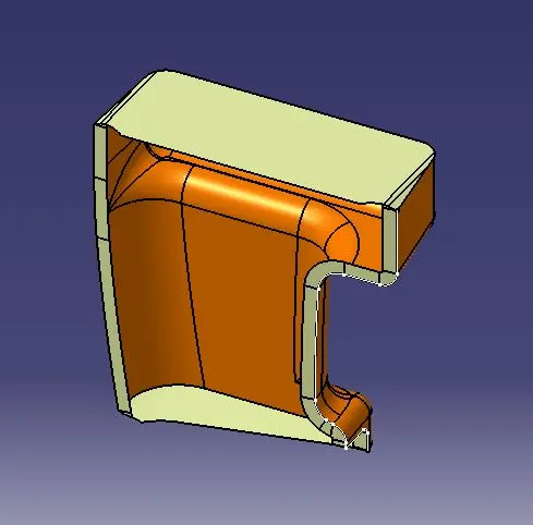
STEP-3: Similarly repeat the above 2 steps for the remaining two sides of the Class-A Surface. Now extrapolate the two sides of the Class-C Surface and trim all 4 sides of the Class-C surface to form a complete Class-C Surface.
Part Body Creation:
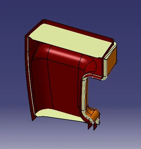
STEP-1: Now join both the Class-A Surface and Class-C Surface by using the Join command and trim them with the Class-B Surface to form a Closed Surface.
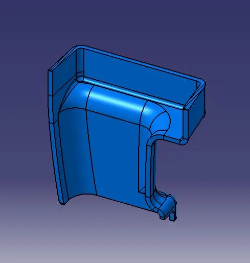
STEP-2: Finally, the Door Handle Plastic component 3D Solid is created by the Close Surface command.
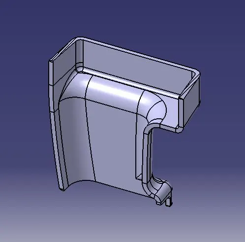
Attachment Feature Creation:
a) Rib Feature:
Design Rules:
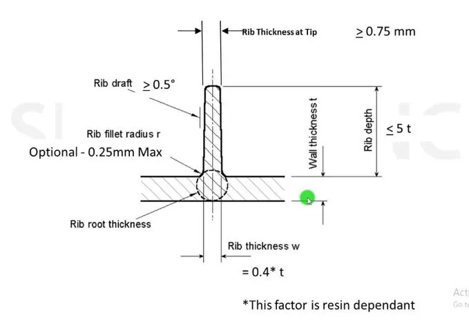
STEP-1: Extract the base surface from the part body and sketch the rib position using the Positioned-Sketch method.
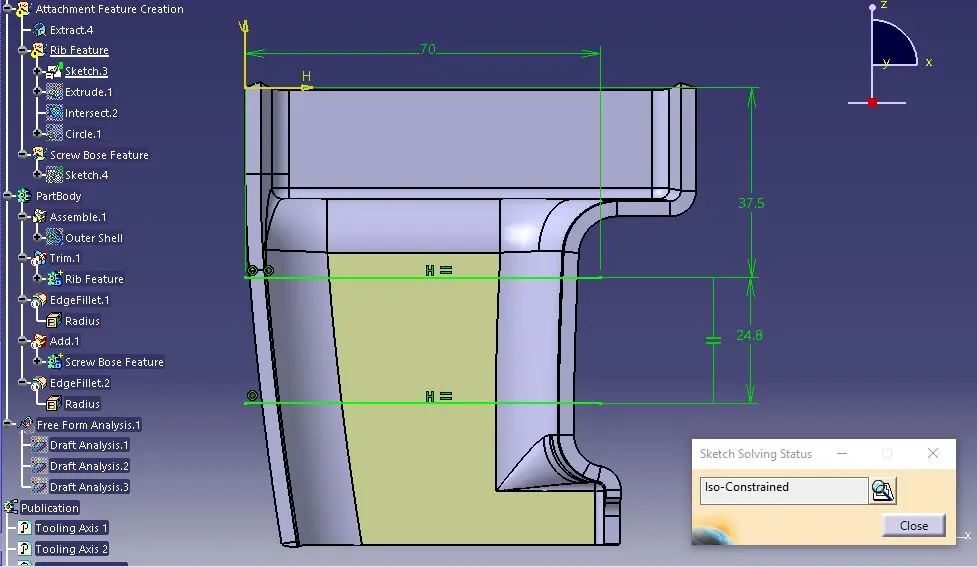
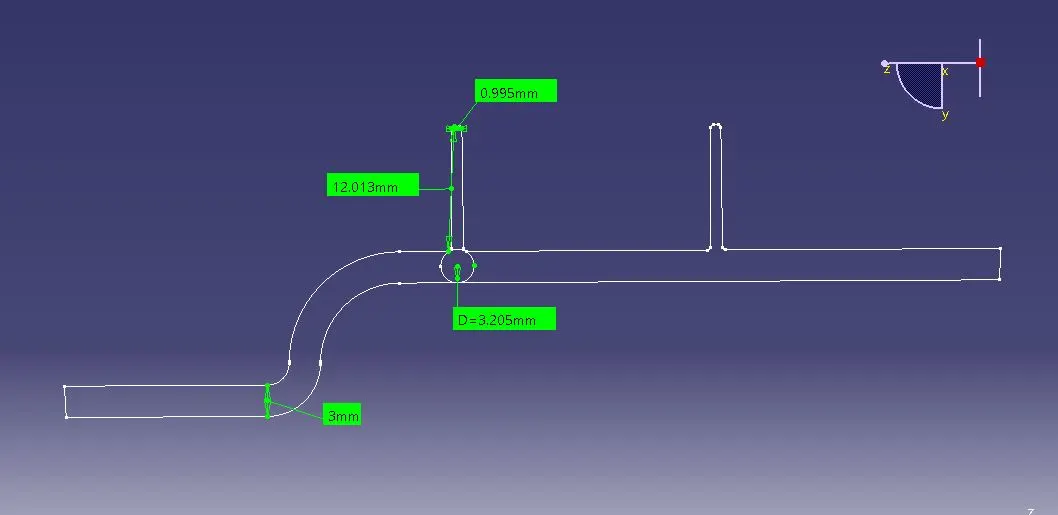
STEP-2: Then Extrude the Surface up to 12 mm (which is < 5t) and thicken it up to 1.2mm.
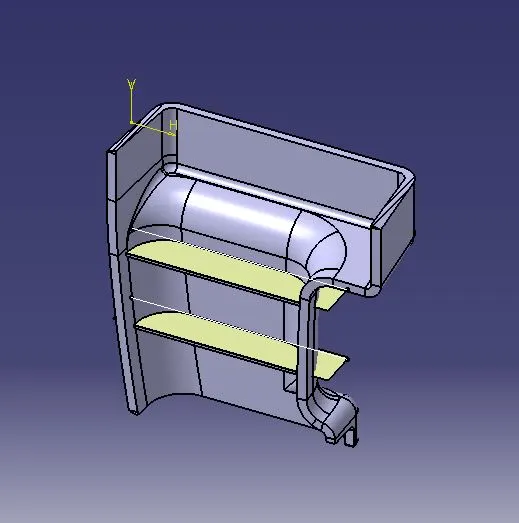
STEP-3: Provide a draft angle of 0.5 deg at the wall thickness and a fillet of radius 0.25mm at all edges of the rib.
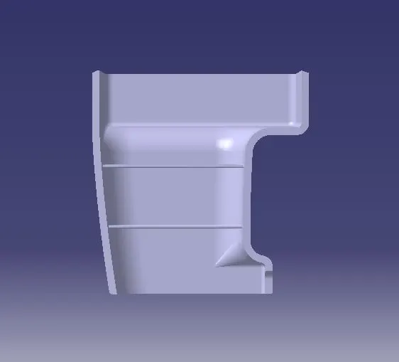
STEP-4: Design Validation
b) Screw Boss Feature:
Design Rules:
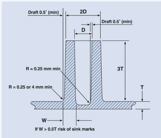
STEP-1: On the extracted base surface draw the screw bose size (drawn for M6 screw) and position using the Positioned-Sketch method.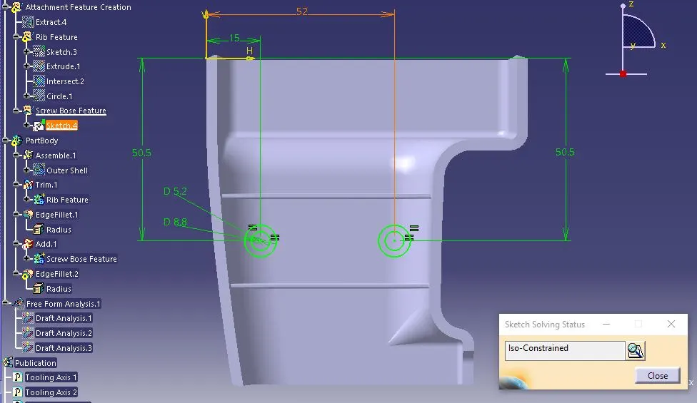
STEP-2: Then Extrude the Surface up to 9 mm and provide the 0.5 draft angle on both outside and inside the screw bose. Finally, provide a 0.25 radius fillet on all the edges of the screw bose.
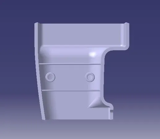
Part-Body Draft Analysis:
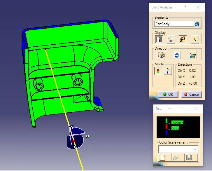
Draft analysis on the solid part resulted in green and blue regions.
1) The green region states that the part is toolable or produceable by the molding machine and the draft angle is 0.5 deg for ribs and screw bosses.
2) The blue colour region in the part is shown as the tolling axis direction is opposite to the surface, which is not an issue.
3) The red colour which is not there, in this case, states that the draft angle is less than 3 degrees and cannot be produced in a normal quality moulding machine even though if produced it will result in faulty.
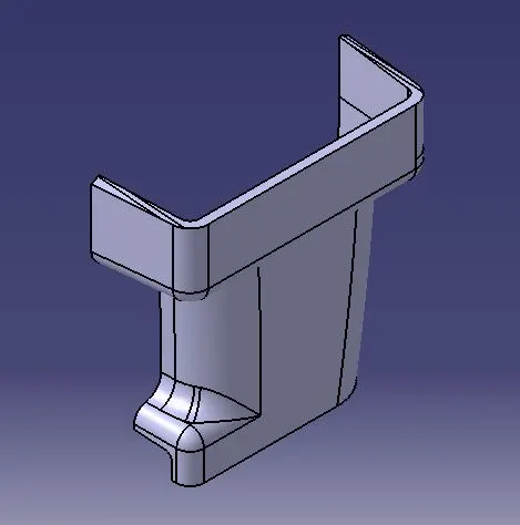
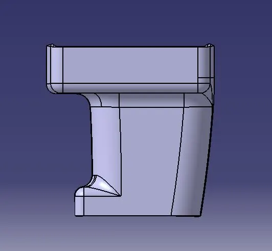
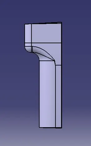
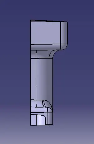
Various Views of Base Bracket:
Isometric View:
Front View:
Side View:
Conclusion:
Thus, the Door Handle Plastic 3D component is created with the ribs and screw bosses in Catia software by following the design guidelines and standards.