Week 10 - Challenge 1- Attachment Feature Creation (Ribs & Screw Boss)
AIM:
Create the Door Drill Handle component through the given Class-A surface. To begin with, the tooling axis for the given Class-A Surface should be created meeting the requirements of the draft angle and at the end perform the Draft analysis on the model. And Create the Rib and Screw boss for the Drill Handle considering the design rules mentioned.
CLASS A SURFACE:
Class ‘A’ surfaces are primarily used in the automotive environment and refer to those surfaces which are visible in a product.
TOOLING AXIS:
Tool axis controls the orientation of the tool axis that will be used to create the toolpath.
TOOLING DIRECTION:
The Tooling Direction is basically the direction that the Mold pulls apart. The Mold is built in two separate pieces, basically. You have a Cavity side and you have the Core side. The Core pulls apart from the Cavity and that's the Dyeline or the Tooling Direction.
DRAFT ANALYSIS:
The draft analysis technique is used to analyse whether our part model created in CAD is manufacturable based on the draft condition applied. Here the part should get easily removed from the panel dies (in case of Sheet metal part) or Mold (in case of plastic).
DRILL HANDLE:
DESIGN PROCEDURE STEPS:
- Open the INPUT CLASS A SURFACE file in CATIA Software.
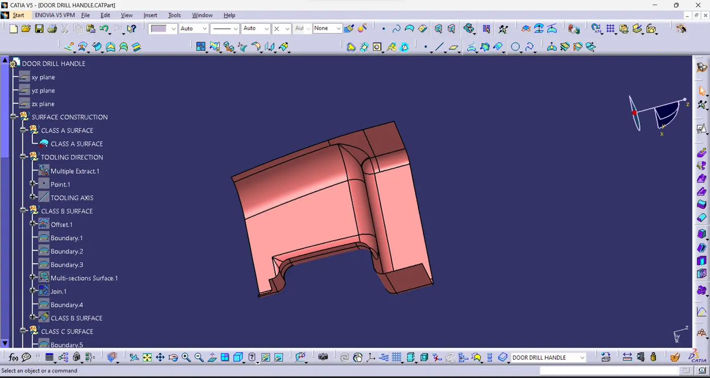
DRAFT ANALYSIS:
Insert > Analysis > Draft Analysis
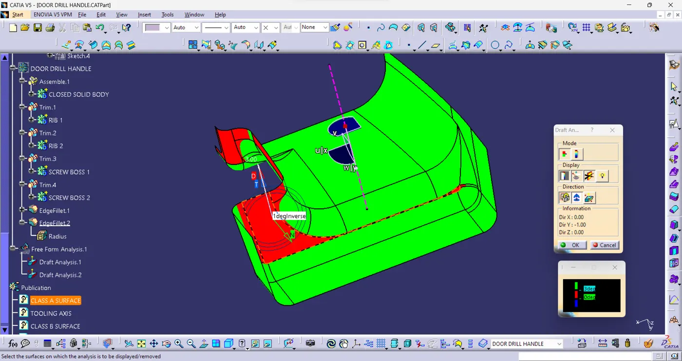
Draft Analysis dialog box with colour scale (with quick analysis mode) appears on the screen. So the first mode option is the quick analysis mode and second is full analysis mode. Here the quick analysis mode is used.
- Drag the compass and place it over to the line.
- Select the compass icon from the direction of the Draft Analysis dialog box. Compass may get misplaced from its original position after clicking on the compass icon.
- Select the compass again and place it over to the line properly one more time.
- After placing it, click anywhere on the part.
- The appearance of the component will change afterwards.
- To get a clear picture, either we need to adjust the compass by holding the marked region of compass and dragging it towards the opposite direction or by selecting the inverses draft direction option inside the direction of Draft Analysis
- Those blue and red negative regions need to be changed green.
- If we are ok with the result, right click on the compass and lock its current position using lock current orientation.
- Class A surface Draft analysis.
- The Maximum possible Draft angle 0.9 Degree.
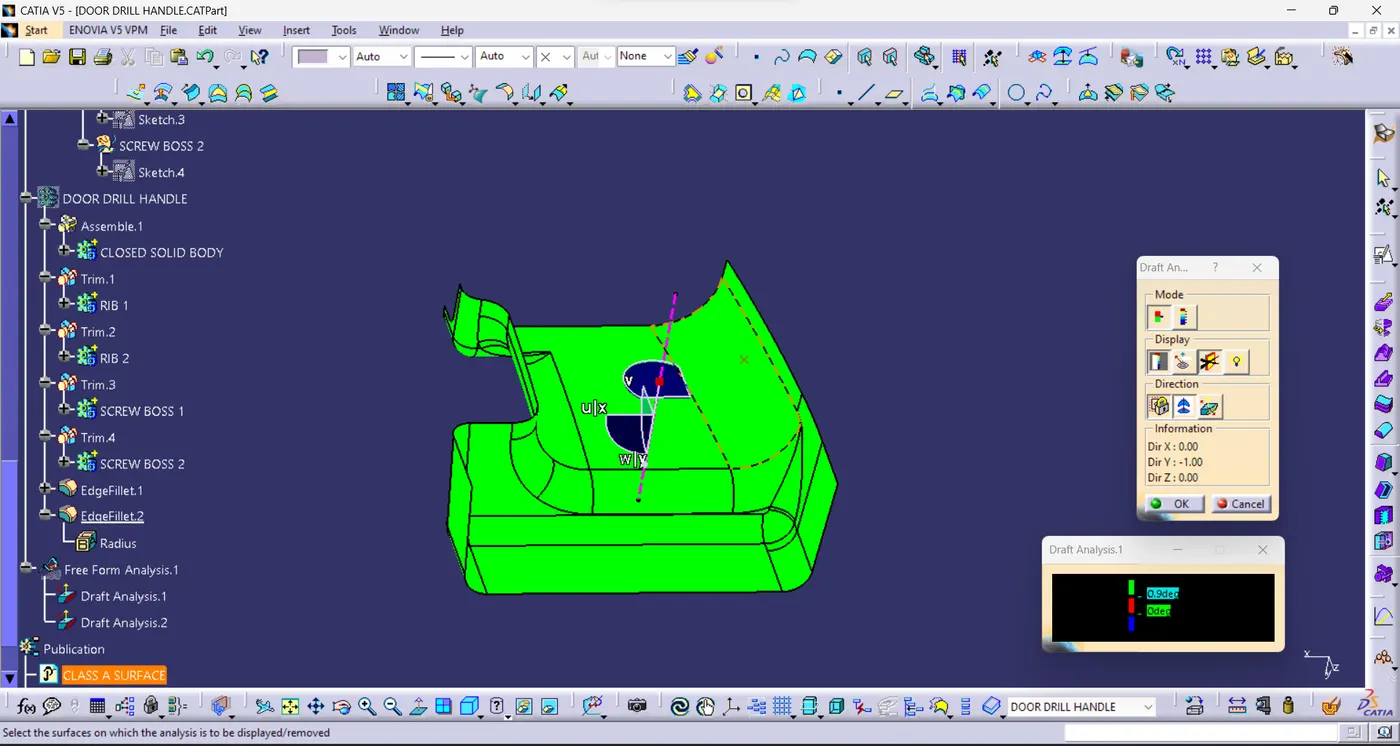
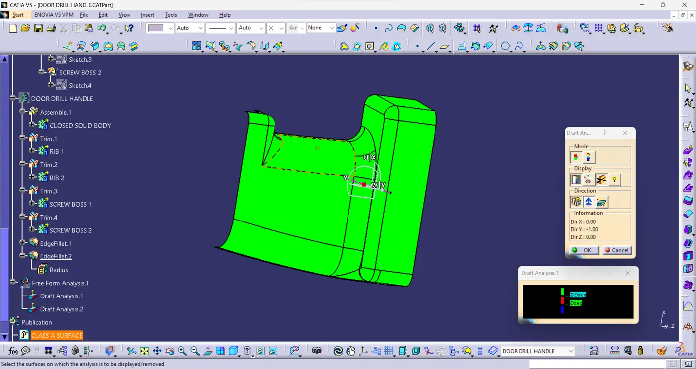
- Create the Point On the Surface to find the TOOLING AXIS.
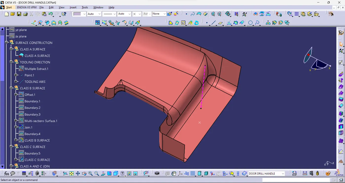
- Create the Class B Surface using the Offset commands.
- Offset distance 2.5mm.
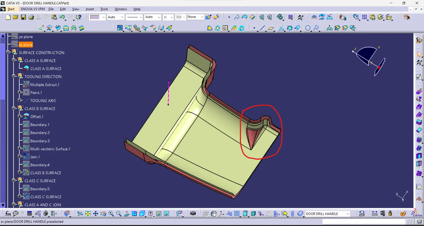
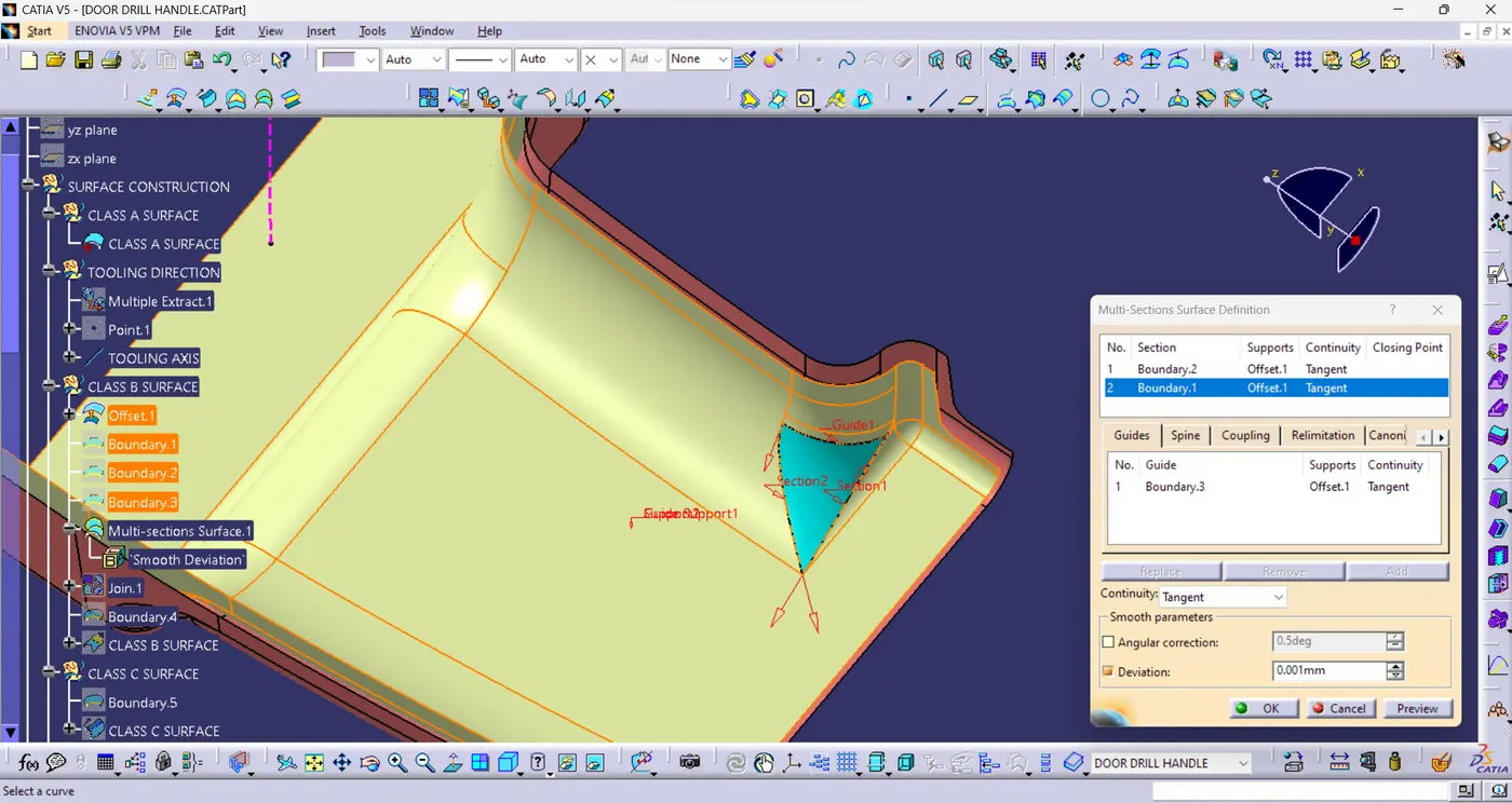
- Use Multi section surface for patch the surface.
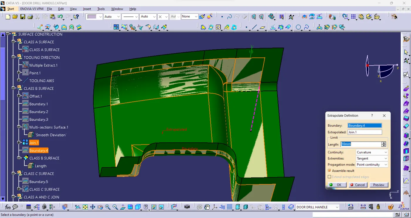
- Extrapolate the Class B Surface.
- Create the Class C Surface using Sweep commend.
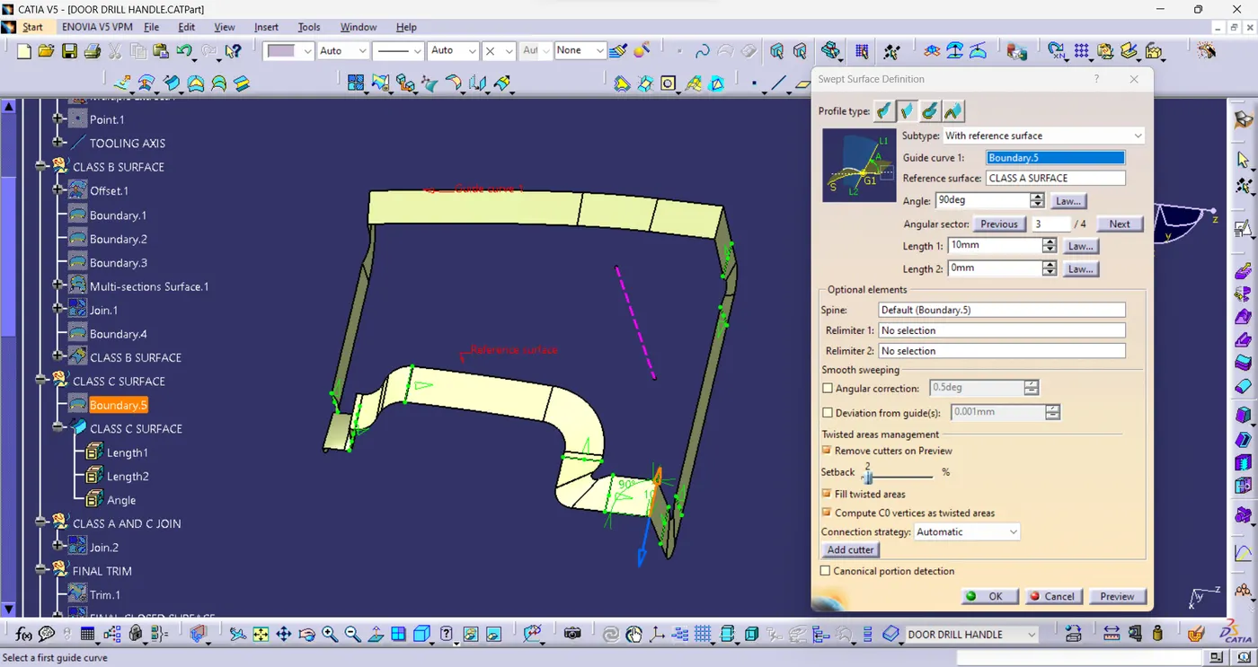
- Join the Class A Surface into Class C Surface.
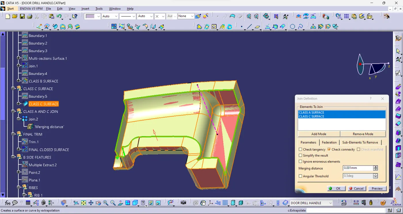
- Trim the Join Surface into Class B Surface.
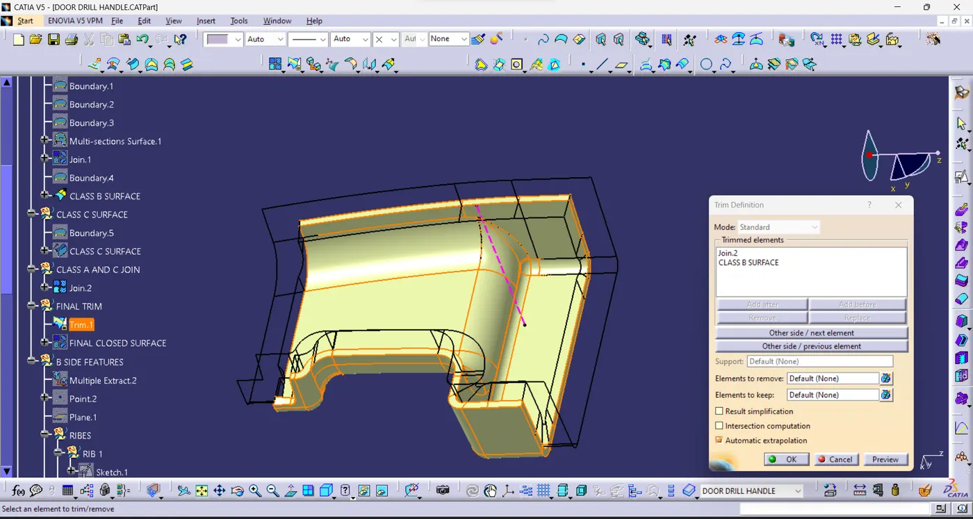
FINAL OUTPUT SURFACE:
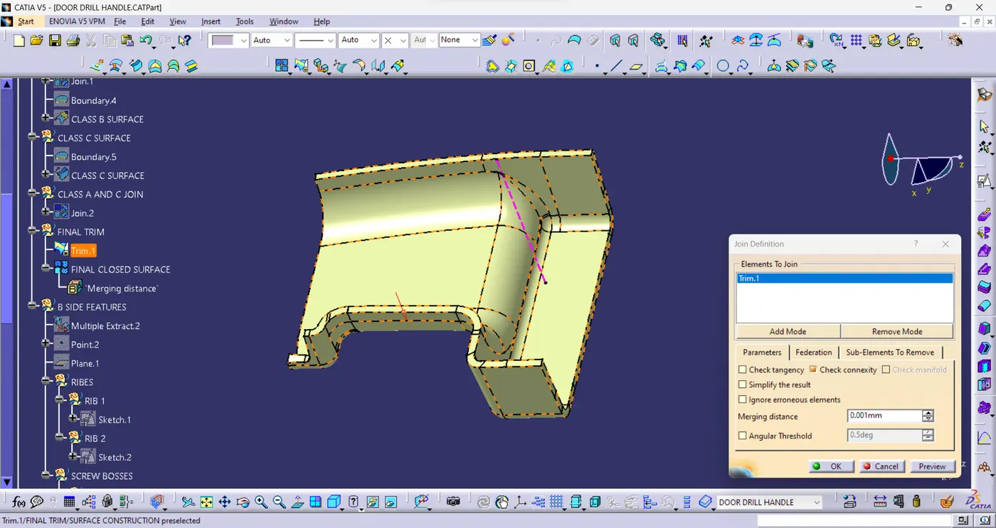
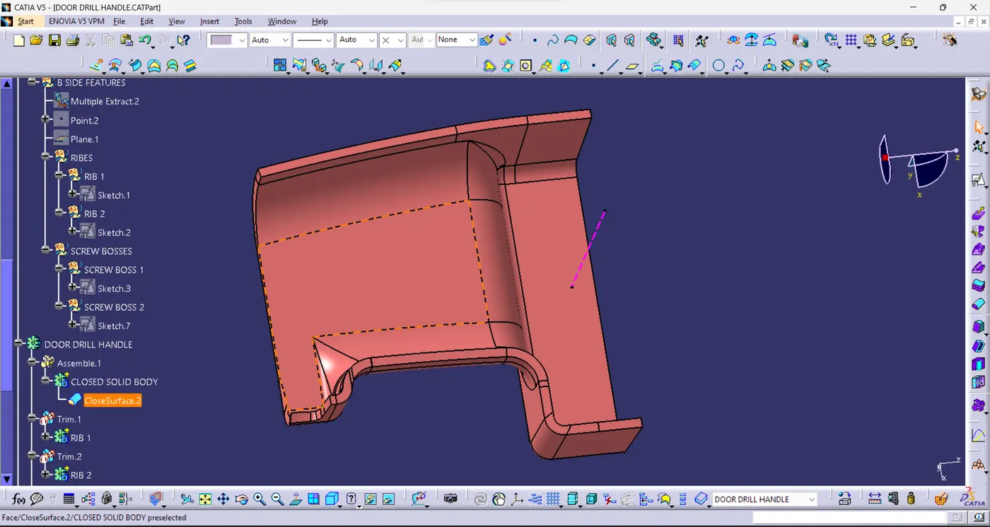
- Create the Solid Body to use the Closed Surface commend.
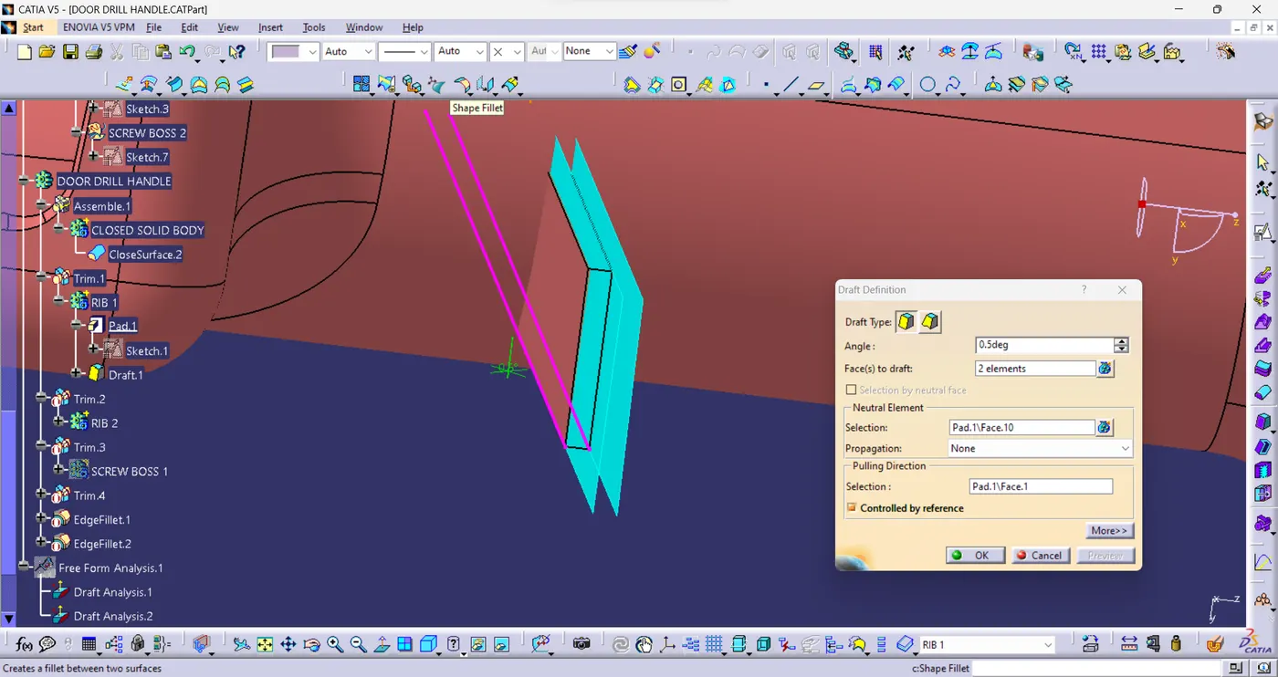
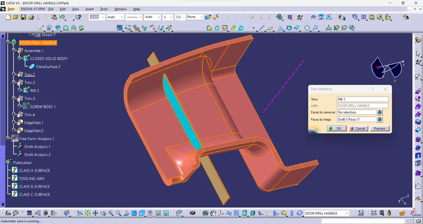
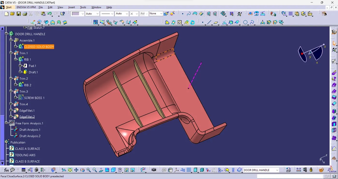
RIBS CREATION:
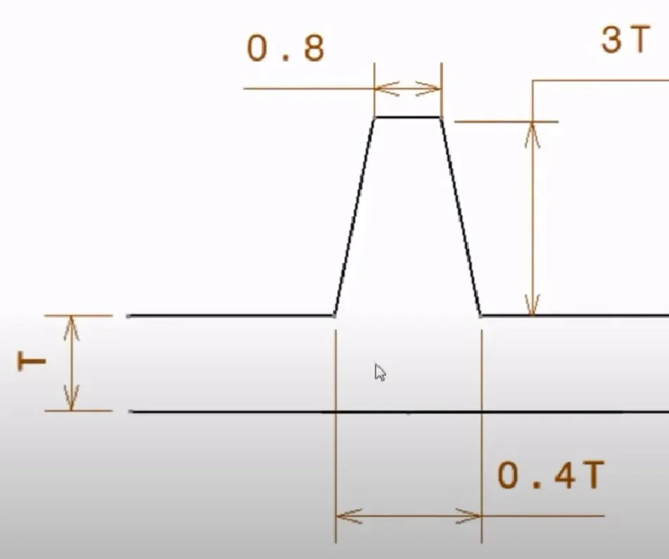
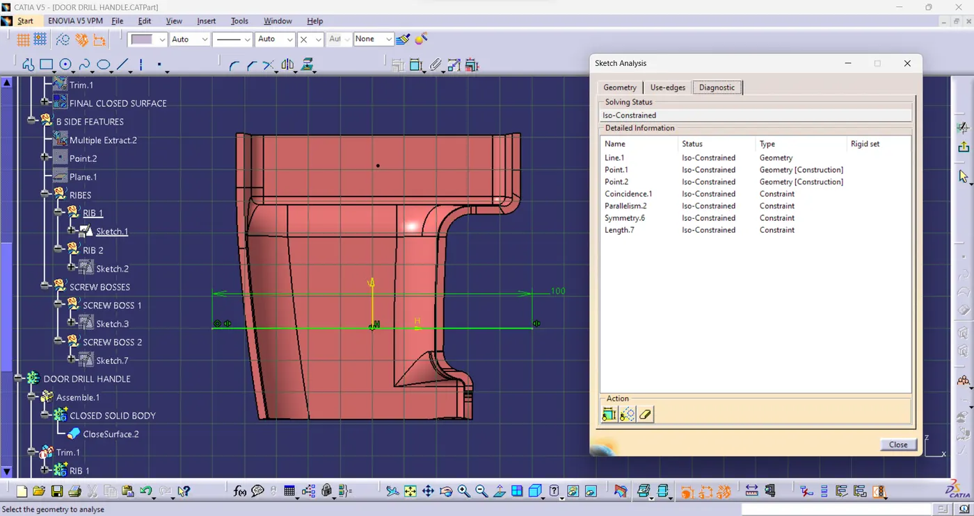
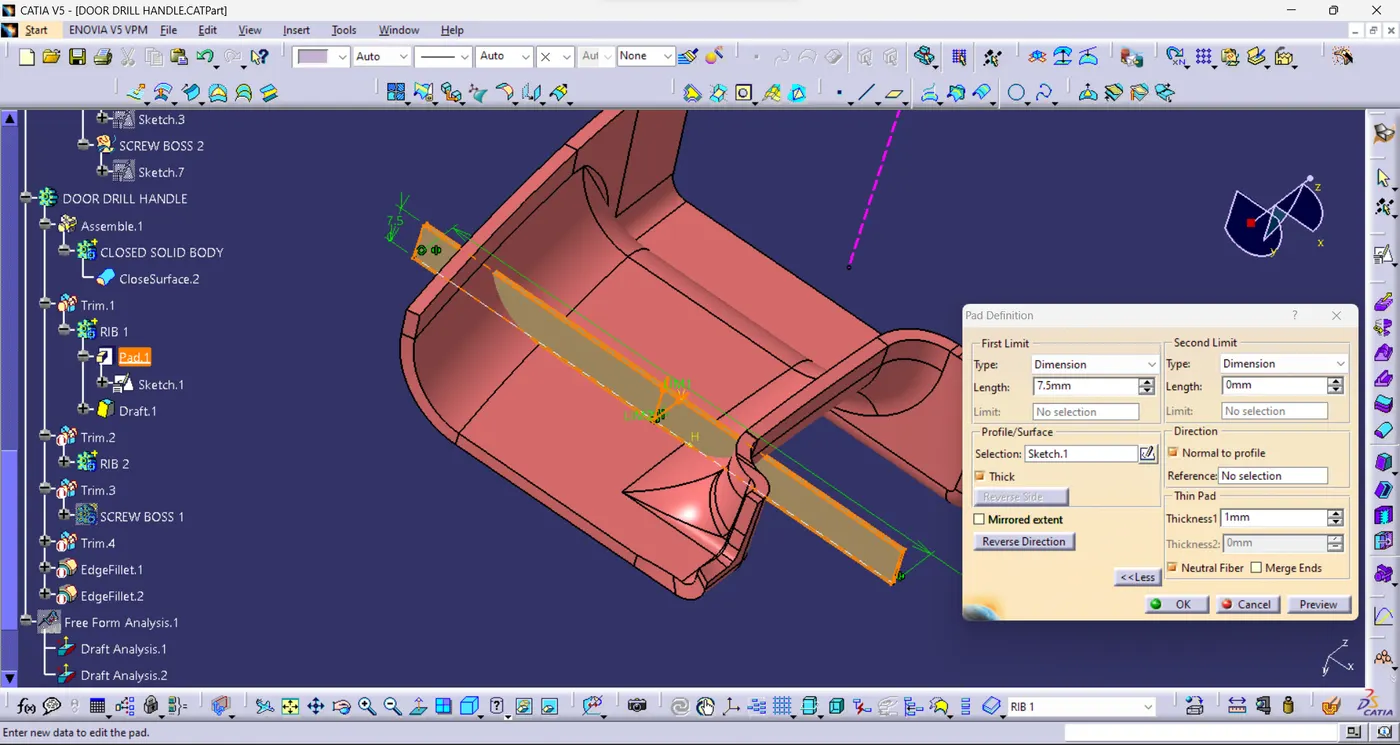
- Draft angle of 0.5 Degree to the Rib feature on parts.
BOSSES CREATION:
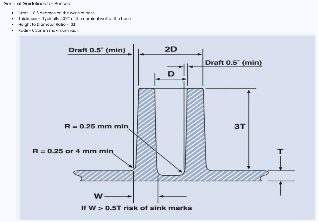
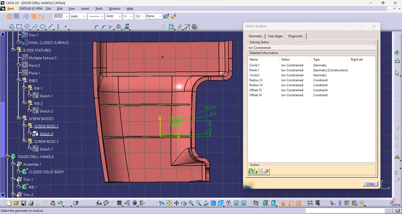
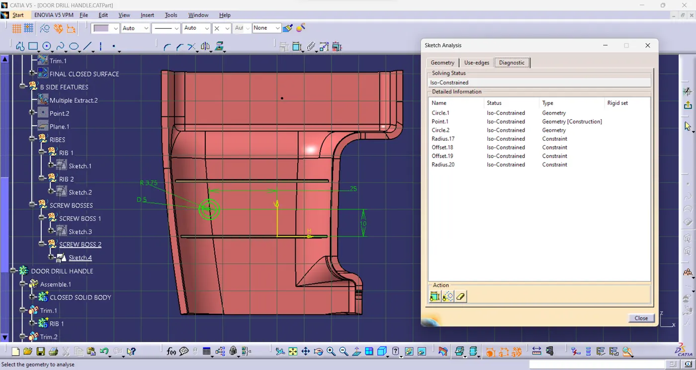
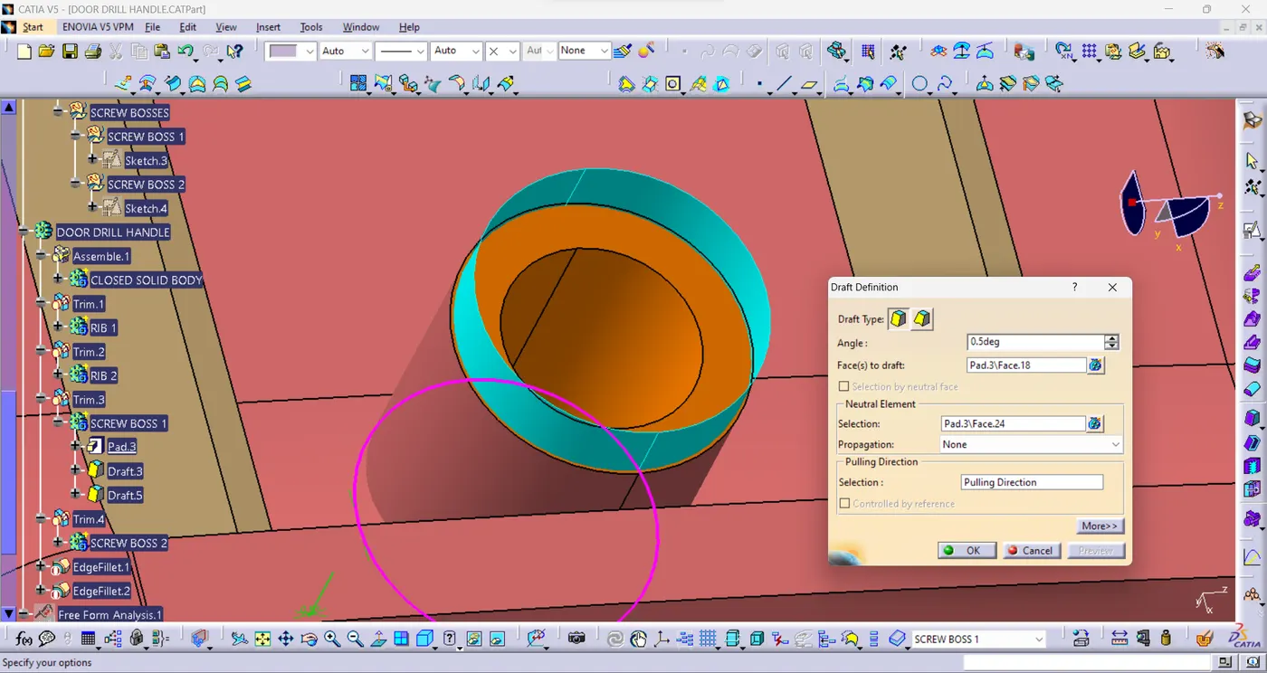
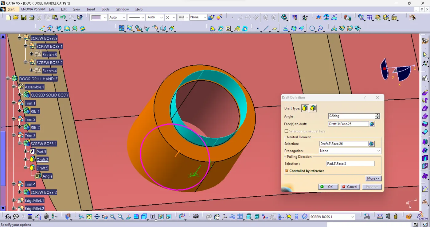
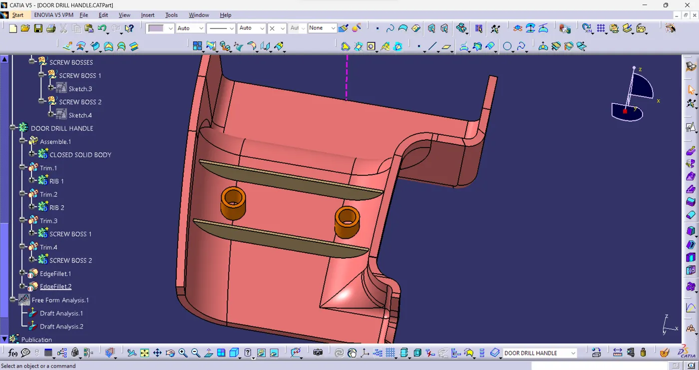
- Fillet the sharp corners.
- The Fillet Radius is 0.25mm.
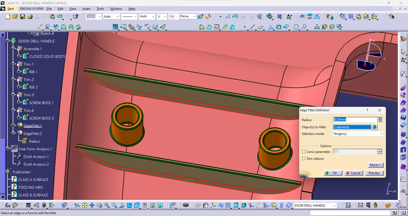
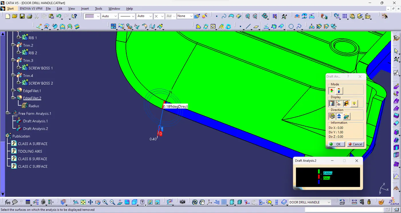
DRAFT ANALYSIS:
- Solid Body Draft Analysis.
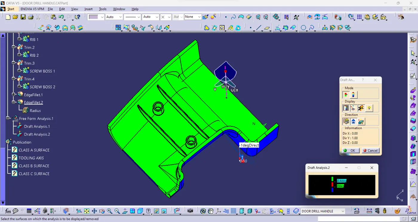
- Inverse Draft Analysis.
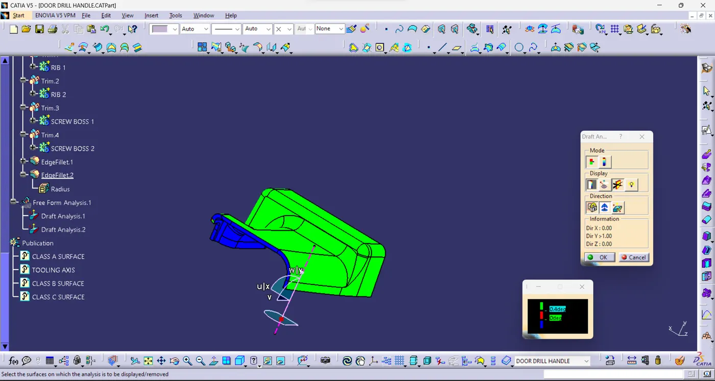
- The maximum possible Draft angle is 0.4 Degree.
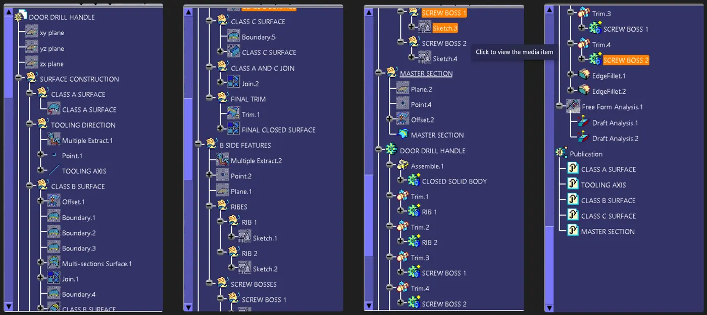
TREE STRUCTURE:
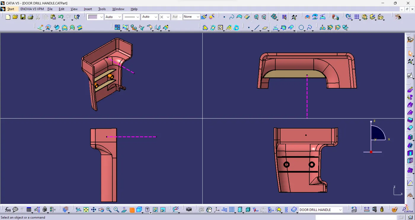
VIEW ORIENTATIONS:
(Isometric, Front, Side and Top View)
CONCLUSION:
Hence, we have studied to Create the DOOR DRILL HANDLE component through the given Class A Surface. And Create the Ribs, Screw bosses, Tooling Axis and check the Draft analysis was completed.