Week 9 - Challenge 1 - Base Bracket Design
AIM:
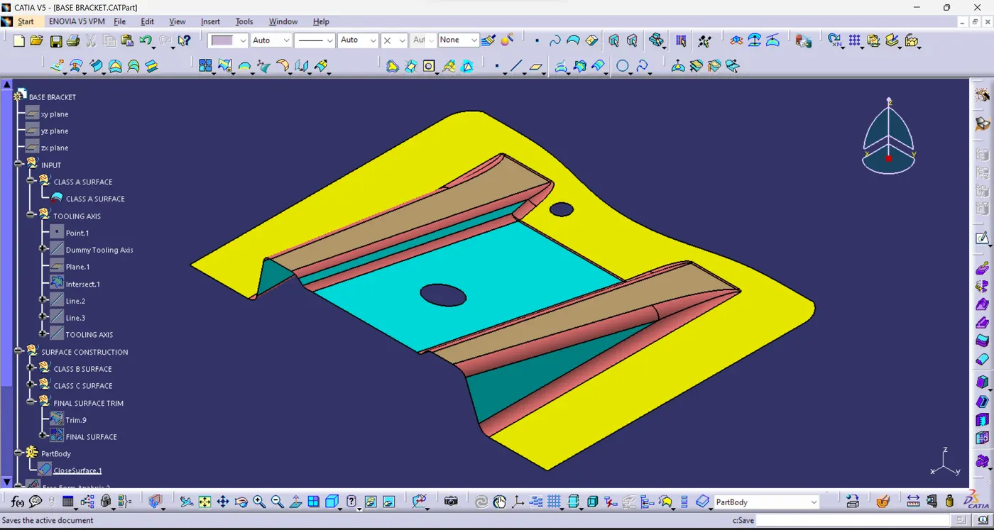
Create the Base Bracket Plastic component through the given Class-A surface. To begin with, the tooling axis for the given Class-A Surface should be created meeting the requirements of the draft angle and at the end perform the Draft analysis on the model.
CLASS A SURFACE:
Class ‘A’ surfaces are primarily used in the automotive environment and refer to those surfaces which are visible in a product. In other words: A - class surfaces are those aesthetic/free-form surfaces, which are visible to us (interior/exterior) and have an optimal aesthetic shape and high surface quality.
TOOLING AXIS:
Tool axis controls the orientation of the tool axis that will be used to create the toolpath.
TOOLING DIRECTION:
The Tooling Direction is basically the direction that the Mold pulls apart. The Mold is built in two separate pieces, basically. You have a Cavity side and you have the Core side. The Core pulls apart from the Cavity and that's the Dyeline or the Tooling Direction.
DRAFT ANALYSIS:
The draft analysis technique is used to analyse whether our part model created in CAD is manufacturable based on the draft condition applied. Here the part should get easily removed from the panel dies (in case of Sheet metal part) or Mold (in case of plastic).
BASE BRACKET:
DESIGN PROCEDURE STEPS:
- Open the INPUT CLASS A SURFACE file in CATIA Software.
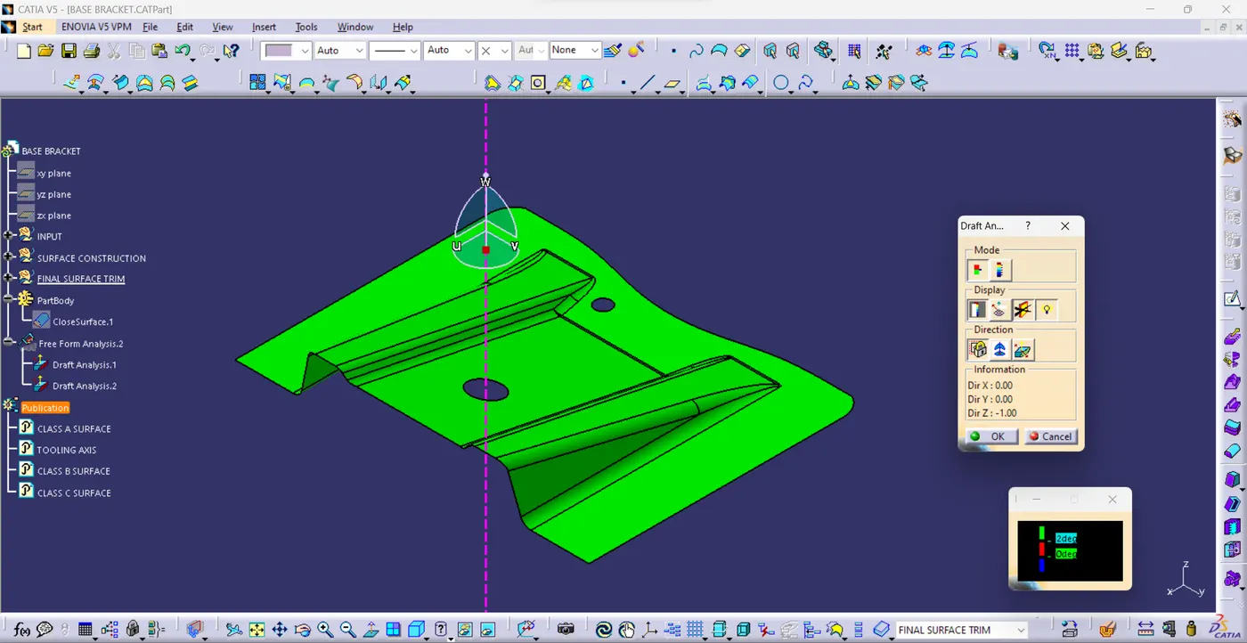
DRAFT ANALYSIS:
- Class A surface Draft analysis.
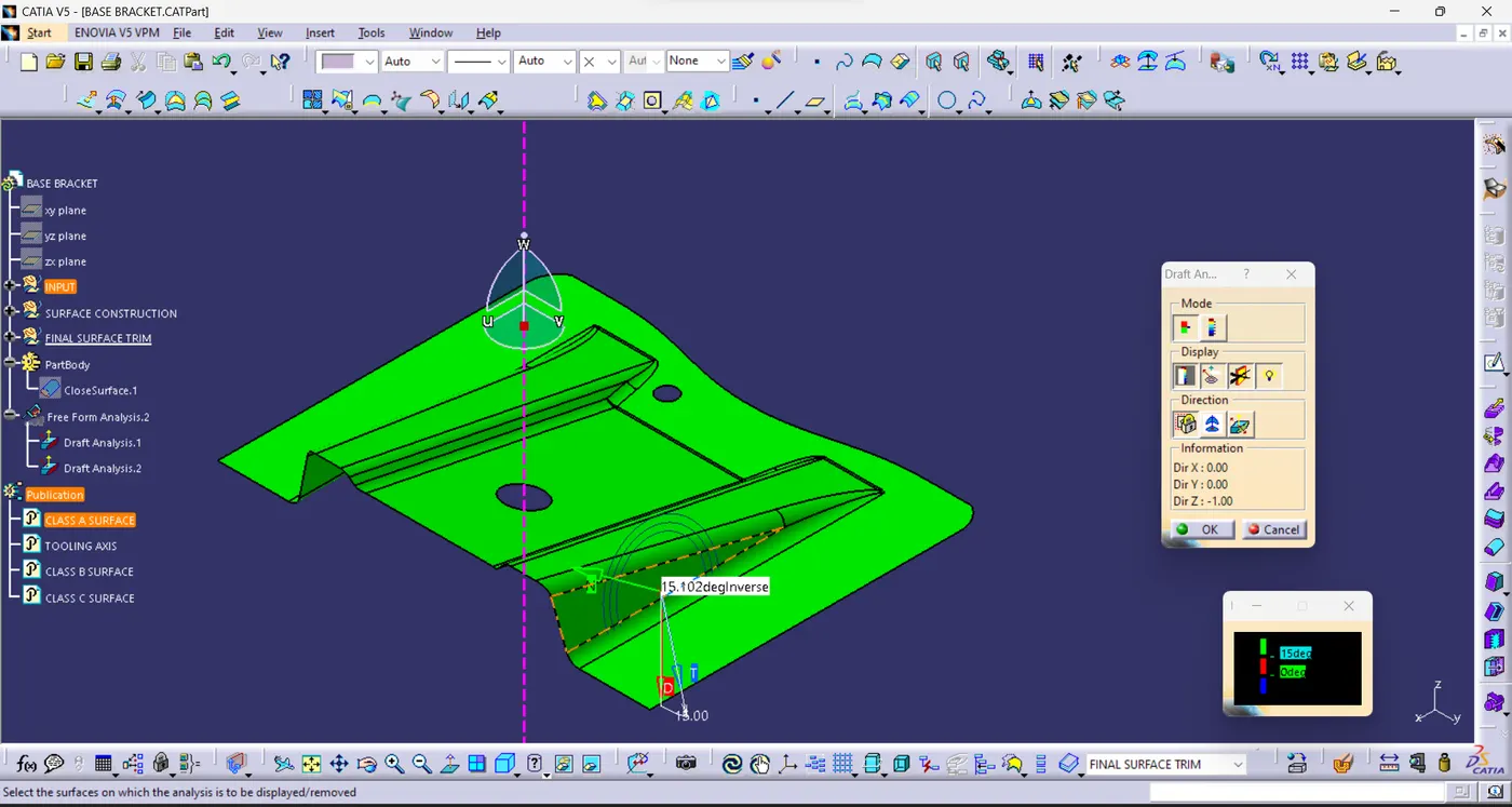
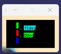
- Maximum possible Draft angle 15 Degree.
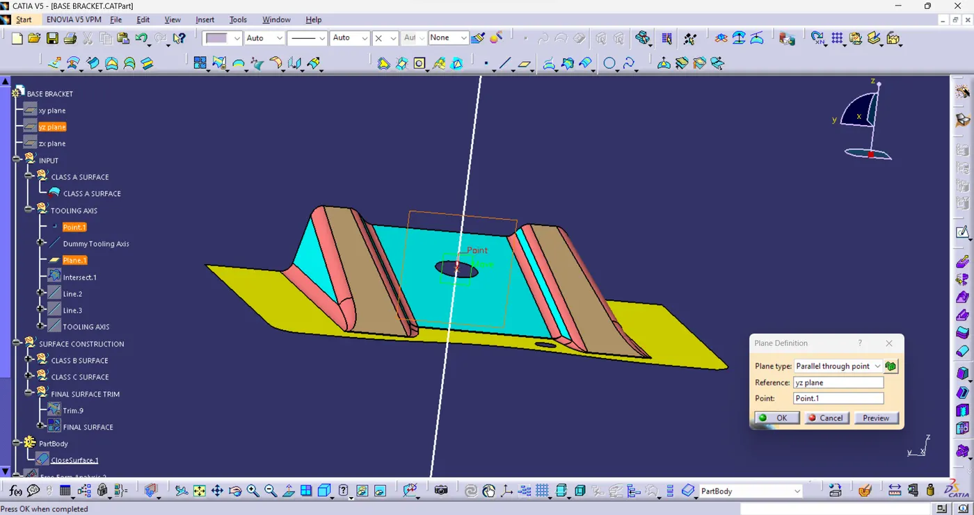
- Create Parallel Plane to the xy plane with reference point.
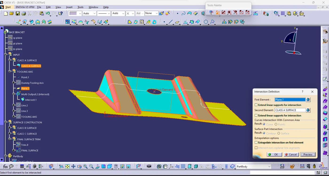
- Create Intersection Line.
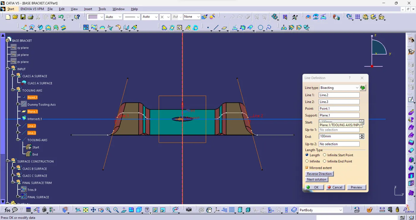
- Create the BISECTING LINE to find the TOOLING AXIS.
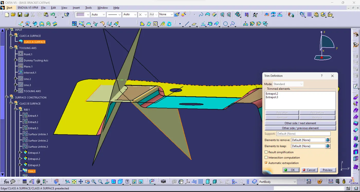
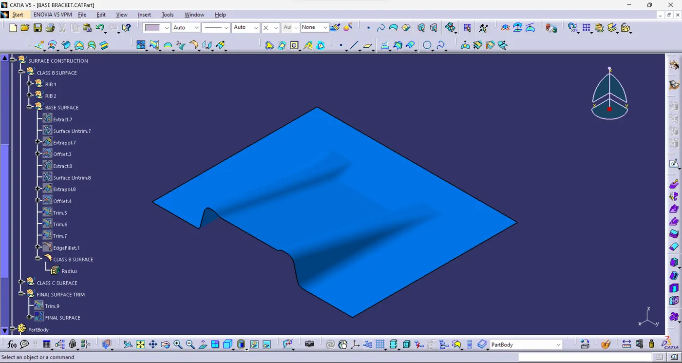
- Create the Class B Surface Rib 1 using the commands.
Extract > Surface Untrim > Extrapolate > Trim > Offset.
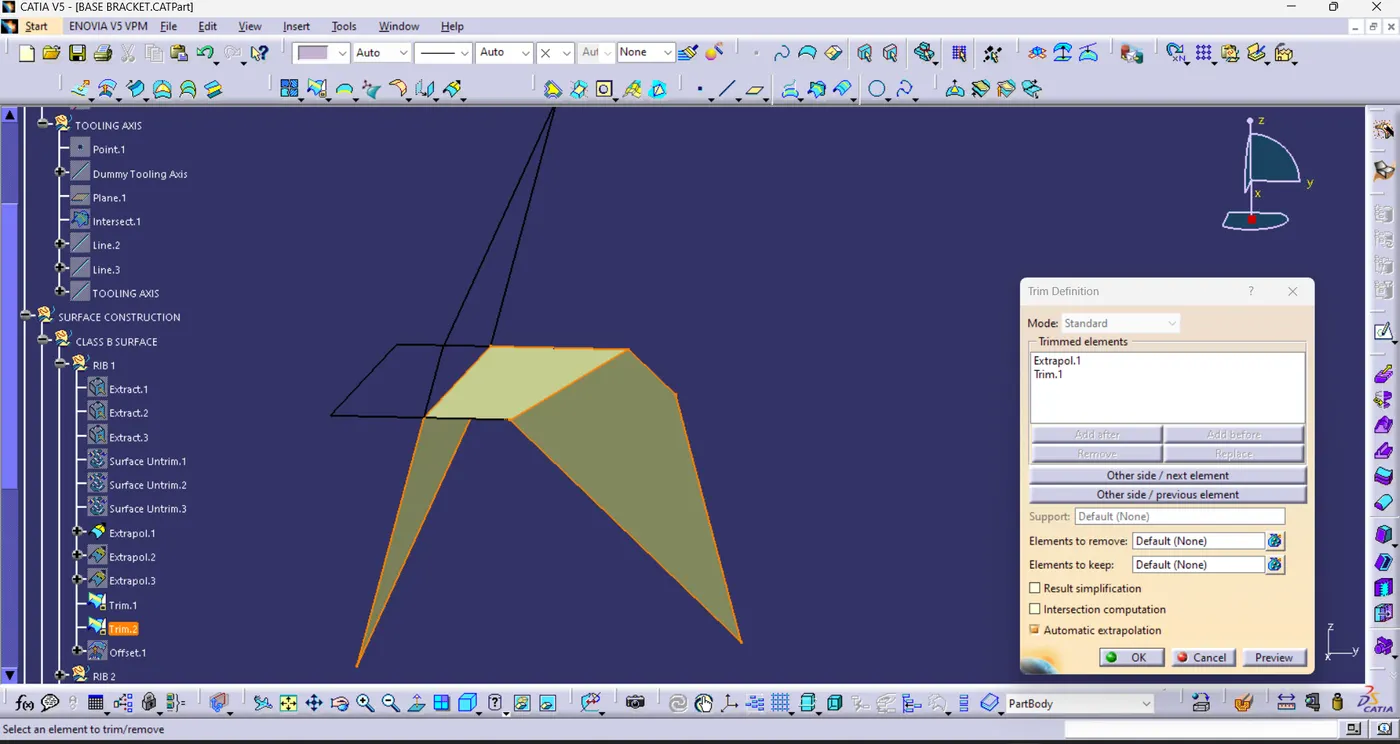
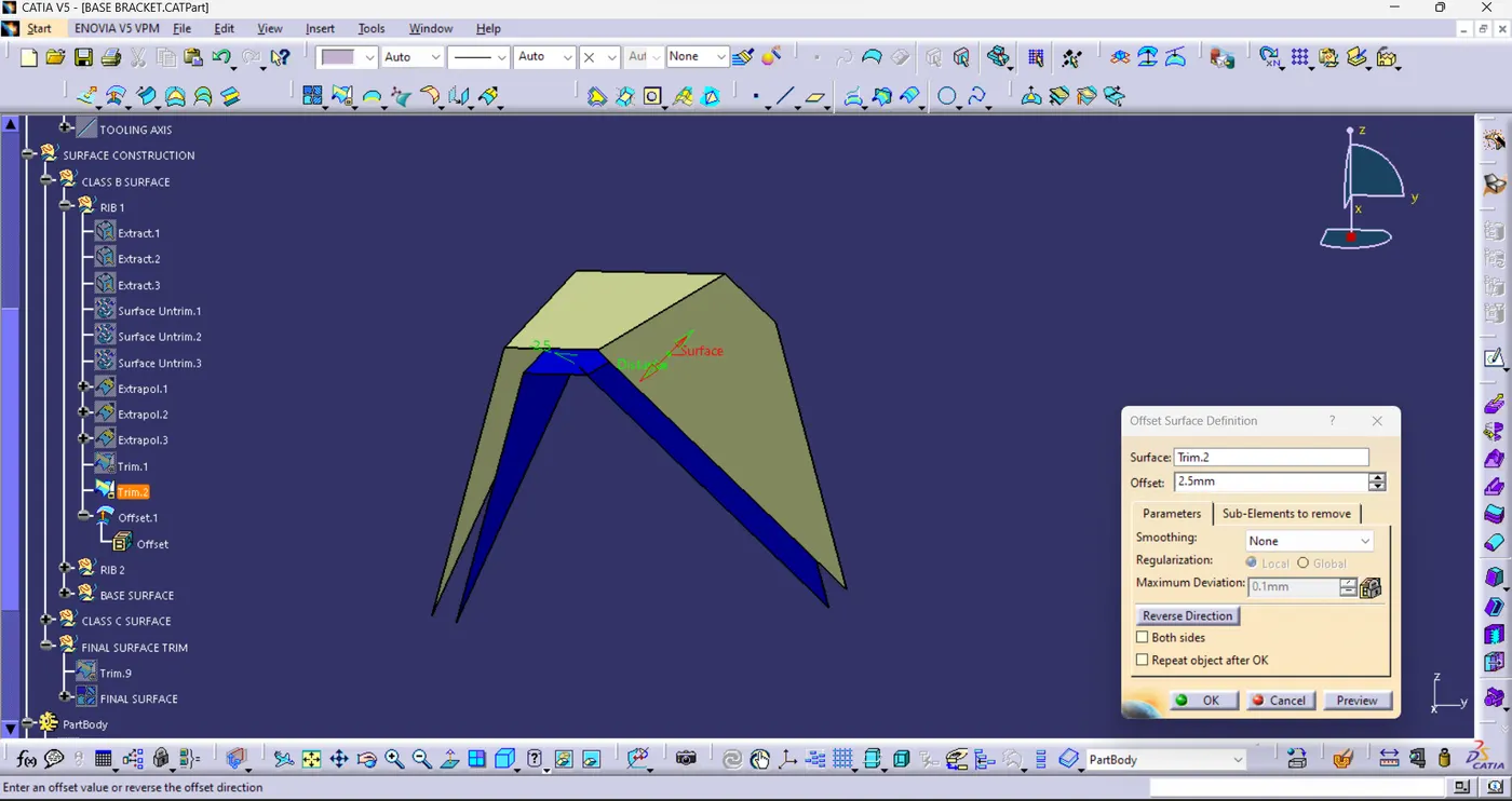
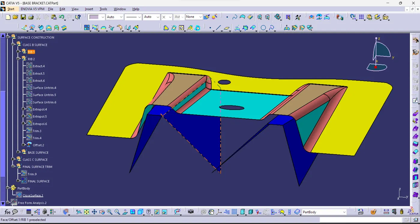
- Same process to Create the Rib 2.
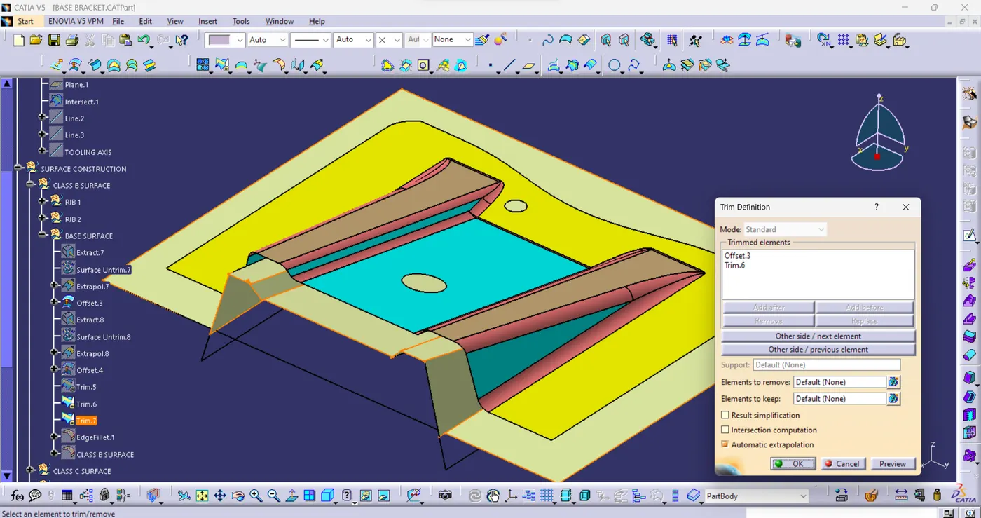
- Trim the Base Surface into Rib 1 and Rib 2.
- Finally use the Edge Fillet commends to fillet the edges.
The Radius of the Fillet is Thickness+Radius (2.5mm + 3mm = 5.5mm).
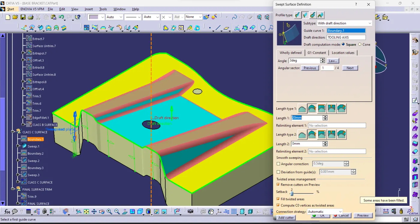
- Create the Class C Surface using Sweep commend.
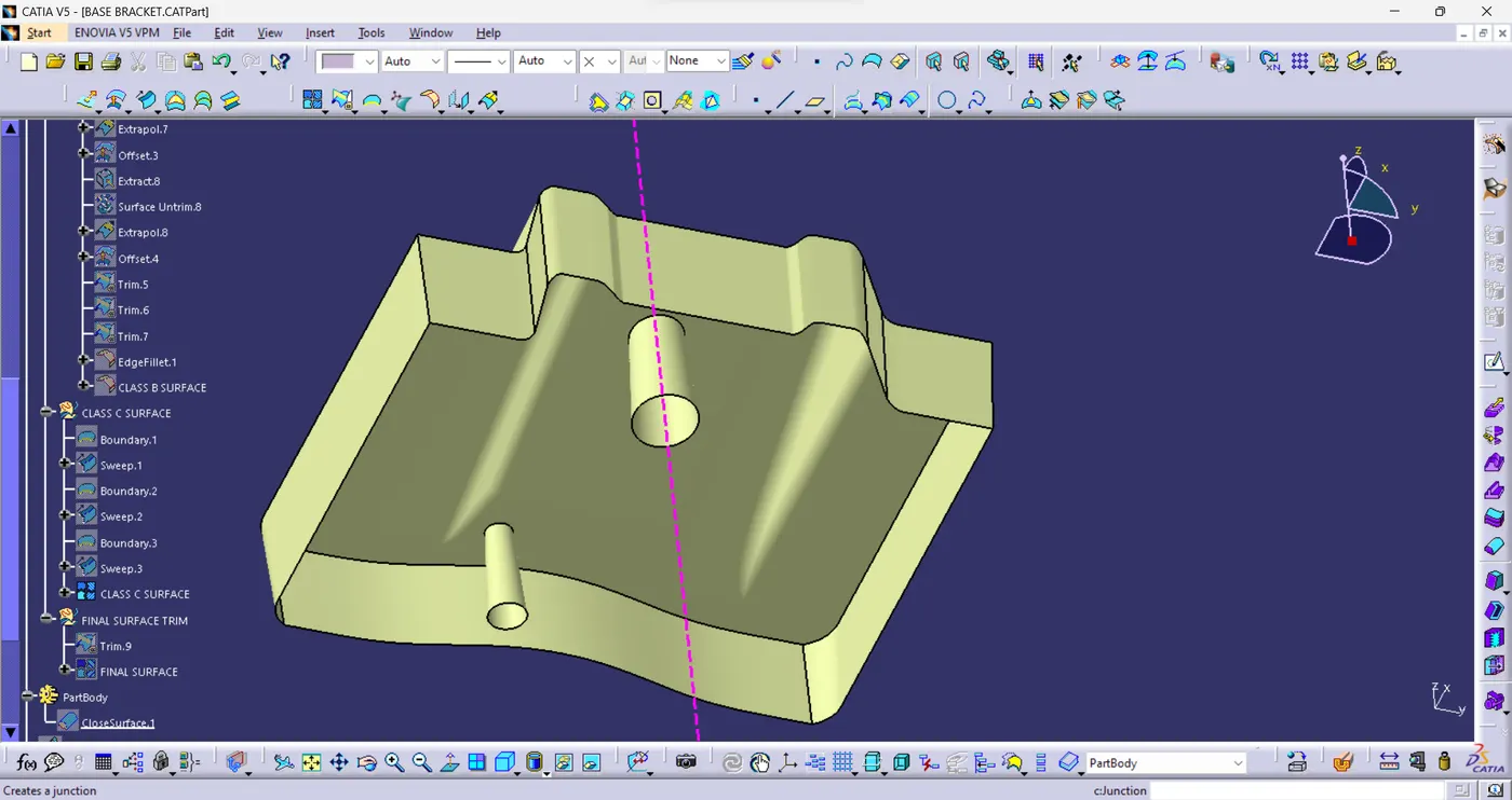
- Join the Class A Surface into Class C Surface .
- Trim the Joining Surface into Class B Surface.
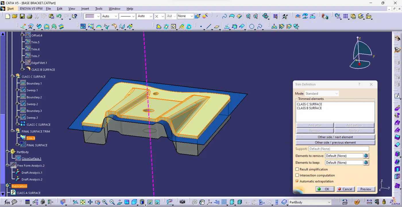
FINAL OUTPUT SURFACE:
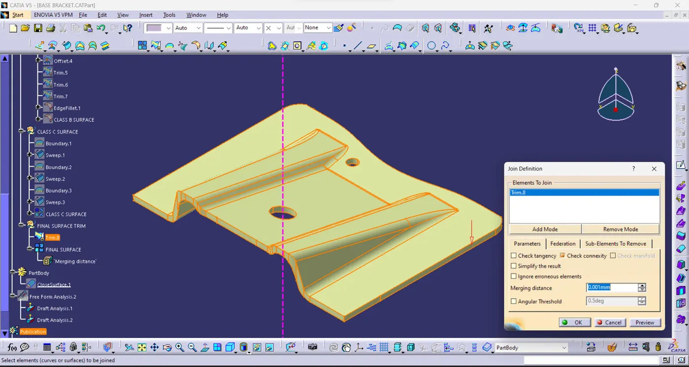
- Create the Solid Body to use the Closed Surface commend.
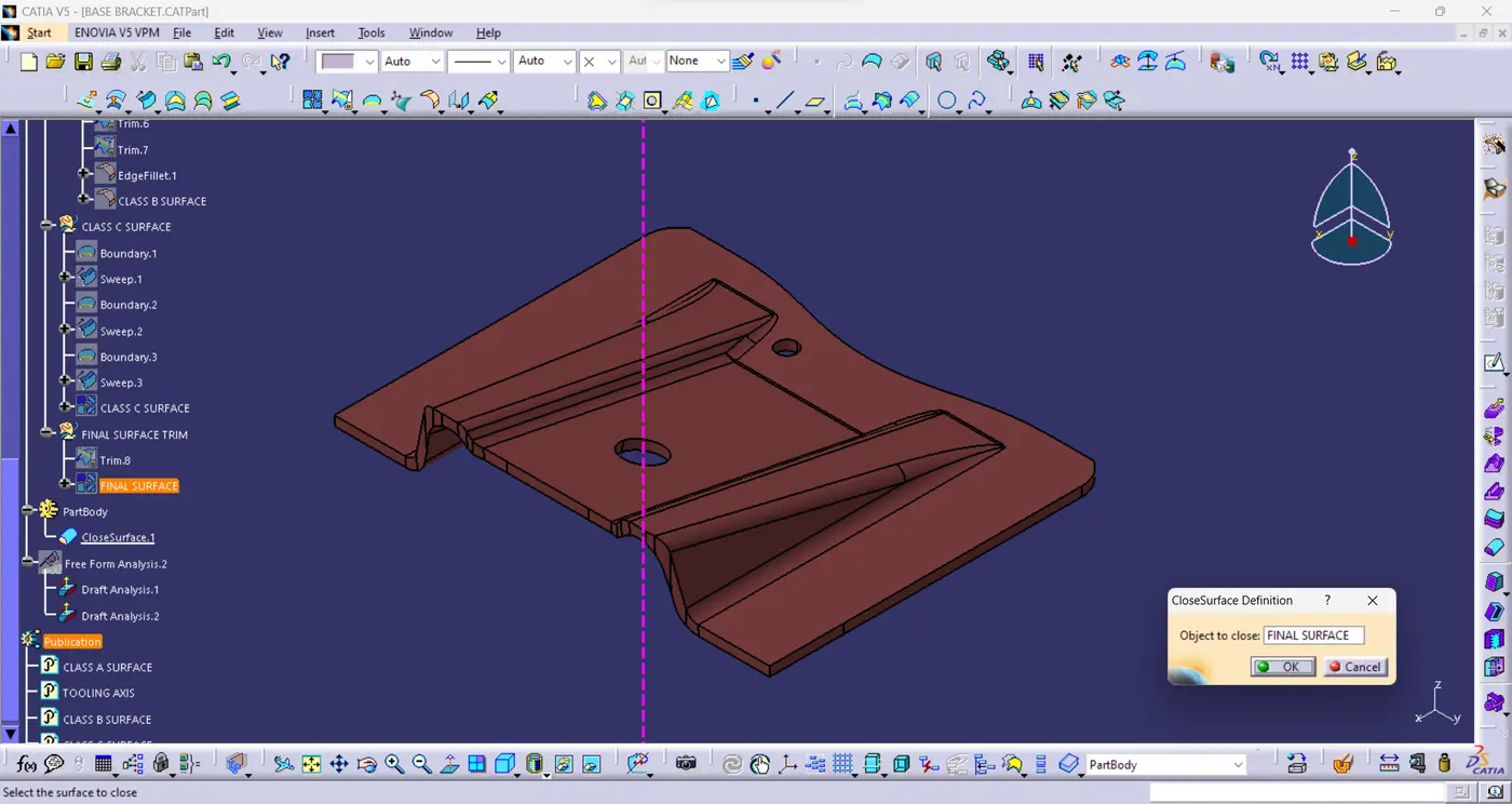
DRAFT ANALYSIS:
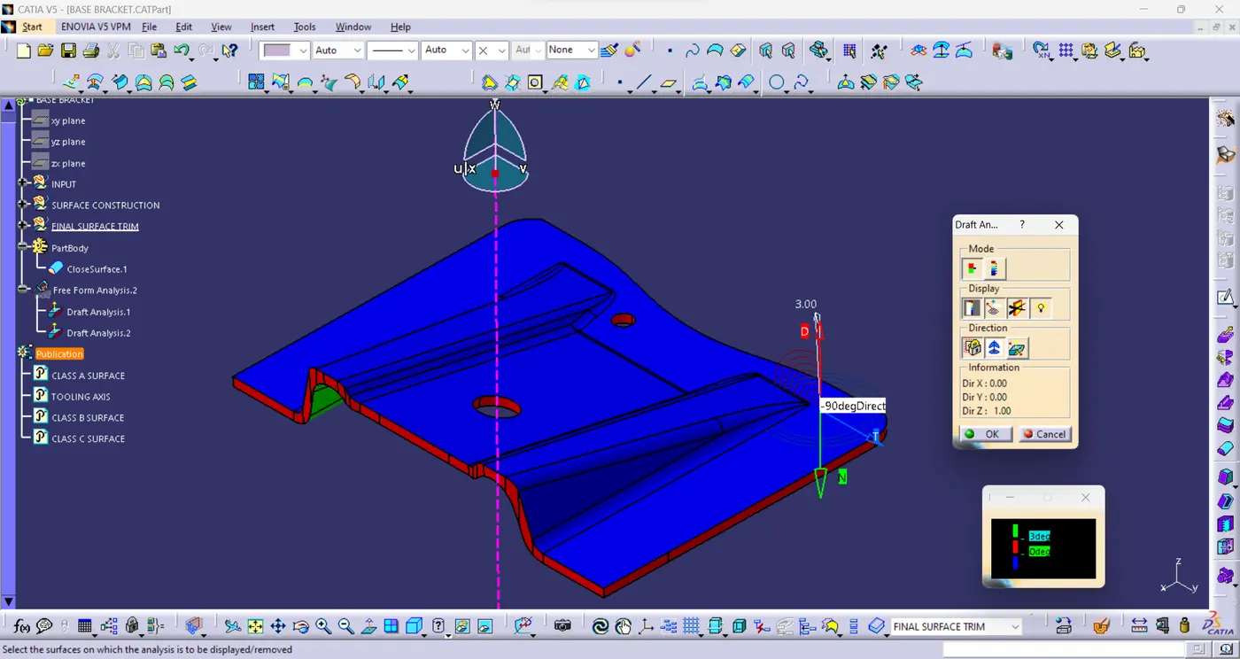
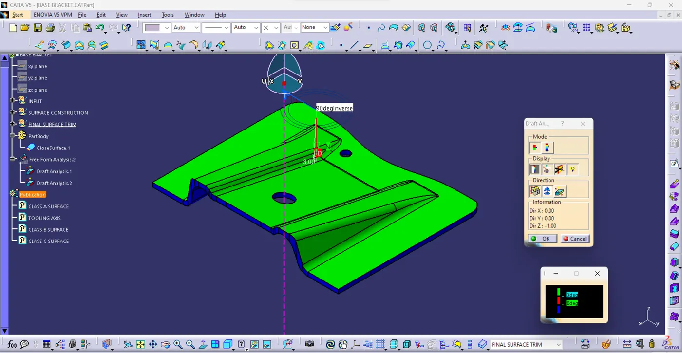
- Solid Body Draft Analysis.
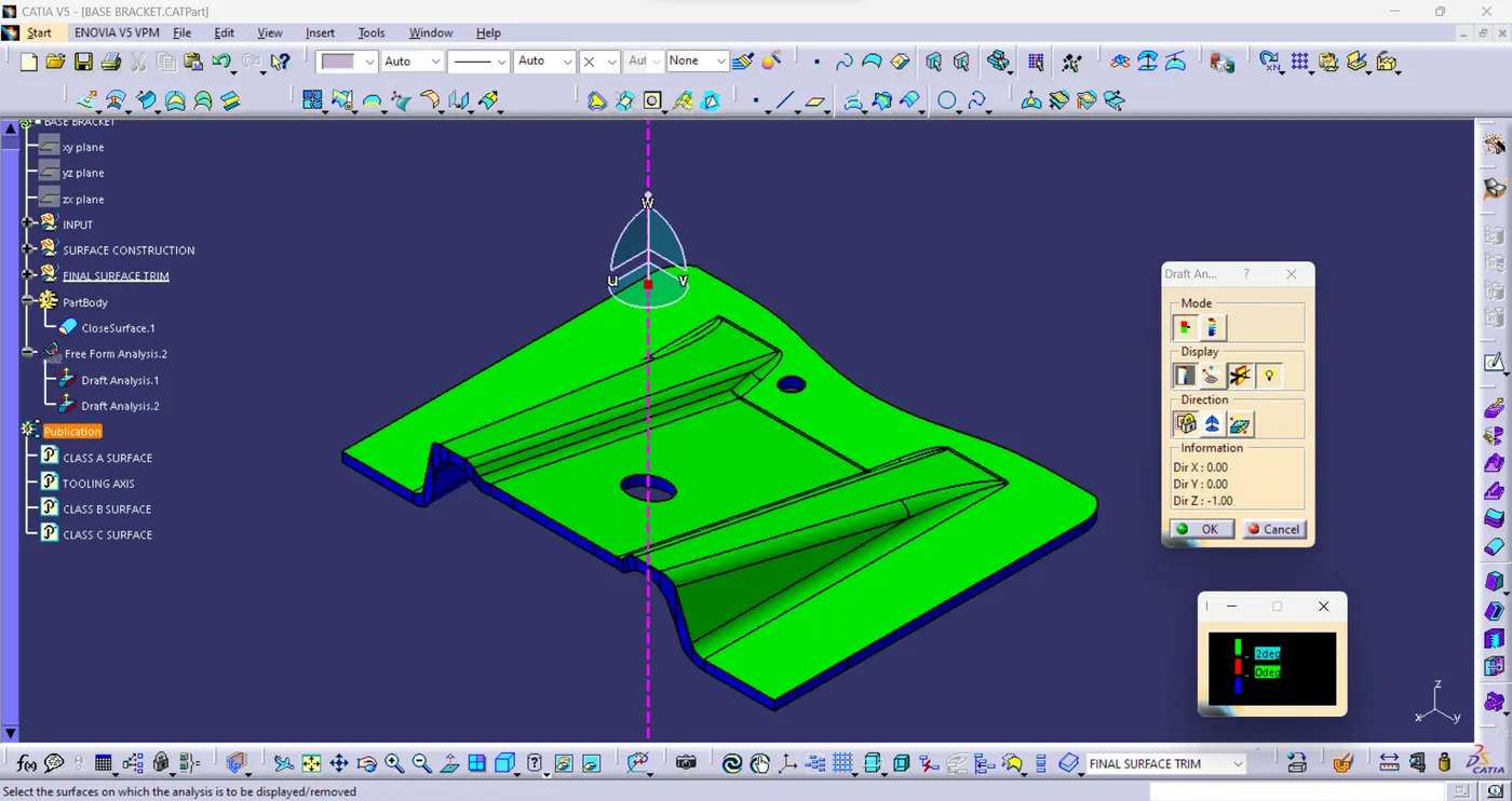
- Change the Draft angle 2.5 degree.
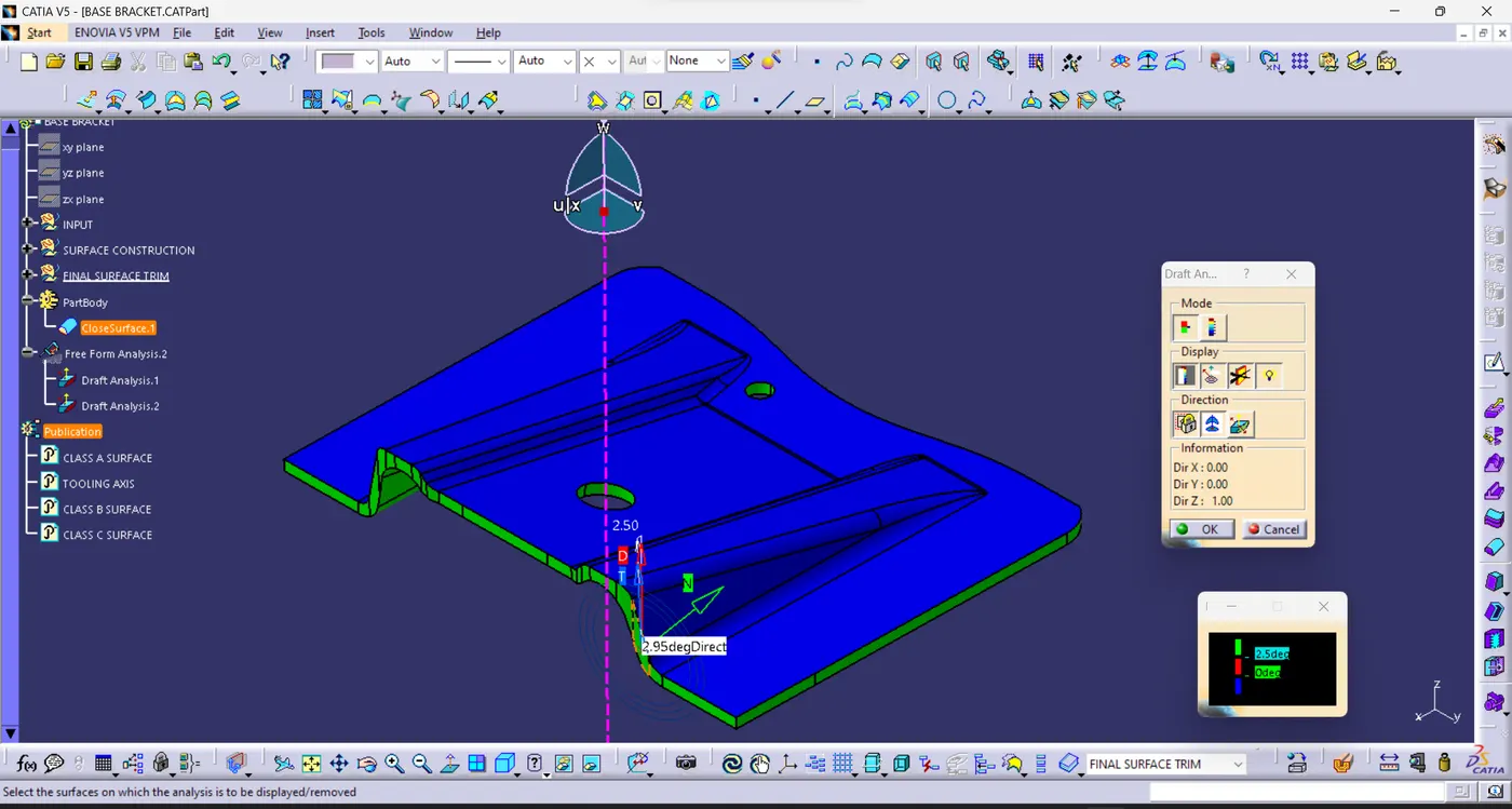
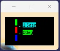
- Change the Draft angle 3 Degree.
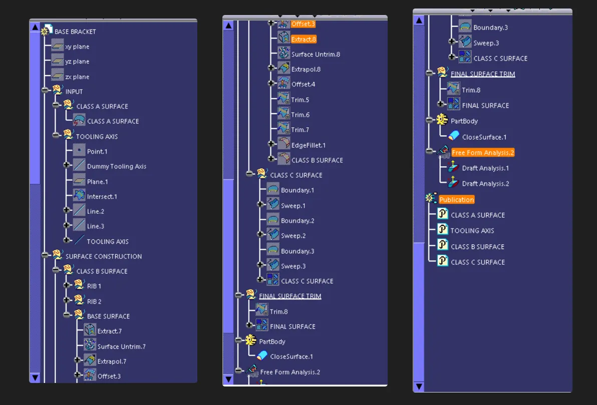
TREE STRUCTURE:
CONCLUSION:
Hence, we have studied to Create the Base BracketPlastic component through the given Class A Surface. And Create Tooling Axis and check the Draft analysis was completed.