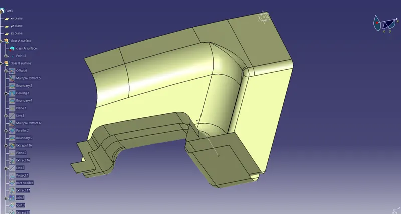
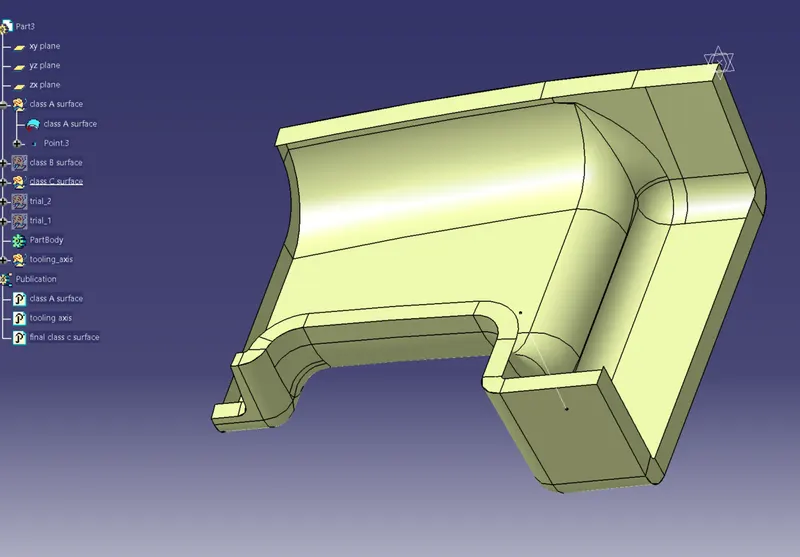
Week 10 - Challenge 1- Attachment Feature Creation (Ribs & Screw Boss)
1. positioned sketches are used.
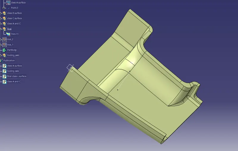
tooling axis creation:
1. fromt he 3 axes: x, y and z; an axis was chosen such that most of the part is visible.
2. then section was taken so that two dummy axes can be formed.
3. then mid line of these two dummy axes was chosen to be the final tooling axis. It was published then.
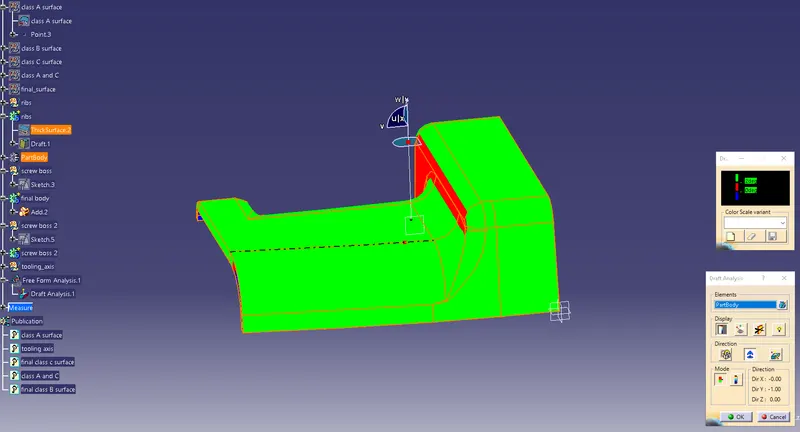
draft analysis:
1. it was carried out by selecting the material in customize view.
2. green areas are which depict a proper drafting of the material.
3. most of the green surfaces should be there in the part, having max of 3 degrees of draft angle if not 2 degrees.
4. after selecting the material part, we drop the axis on the tooling axis to establish the colors, mostly green.
5. this means that the part can be manufactured properly.
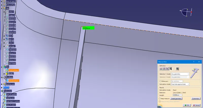
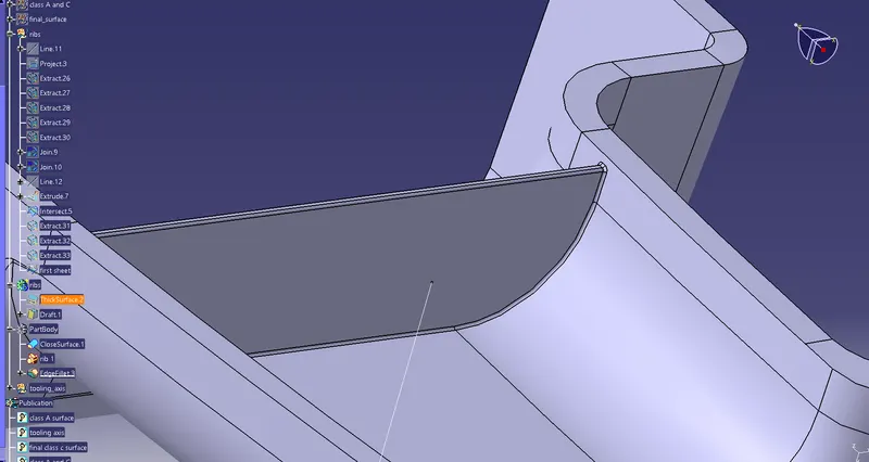
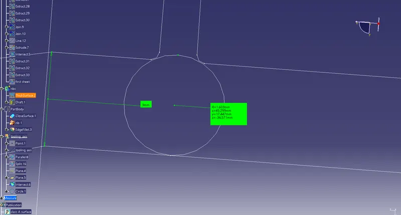
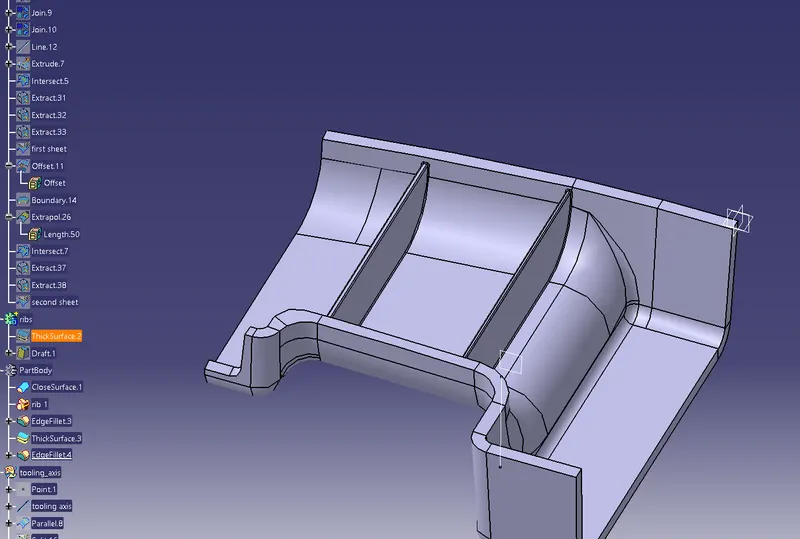
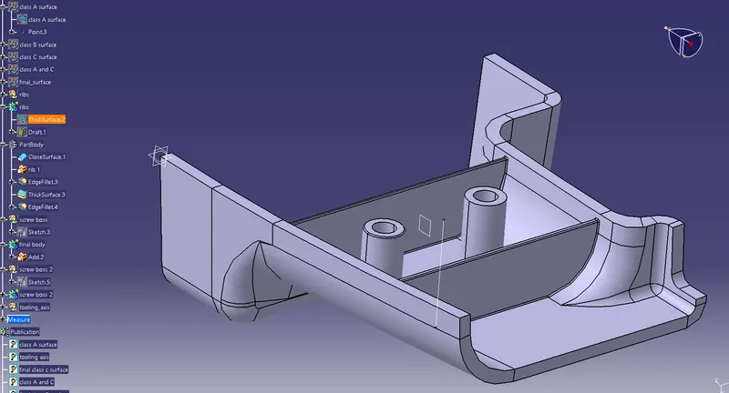
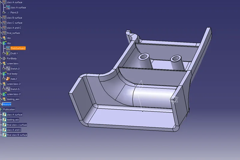
ribs and screw boss were designed according to the design specifications. Measurements are shown in the images.
For screw boss: (M6 screw)
- Draft was taken to be 0.5 degrees on the walls of boss
- Thickness - Typically 40%* of the nominal wall at the base. (here, diameter small was 5.2 mm and outside diameter was 8.8 mm, according to the design rules)
- Height to Diameter Ratio - 3:1
- Radii - 0.25mm maximum radii
For ribs:
- draft angle was 0.5 degrees.
- rib thickness was kept at 0.4 * thickness (here 3 mm)
- rib depth was less than 15 mm (5*thickness limit)
- Rib thixkness at tip as greater than 0.75 mm according to the design standards