Week 10 - Challenge 1- Attachment Feature Creation (Ribs & Screw Boss)
--------------------------------------------------------DOOR HANDLE---------------------------------------------------
TREE STRUCTURE
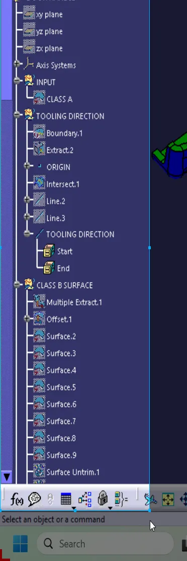
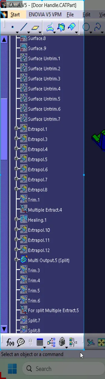
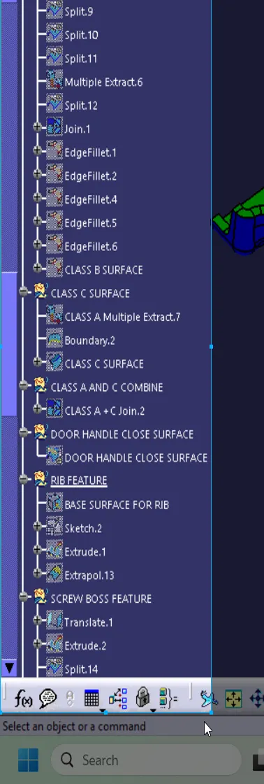
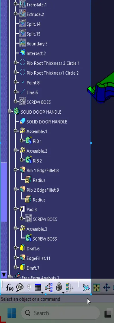
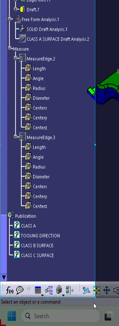
SKETCHES
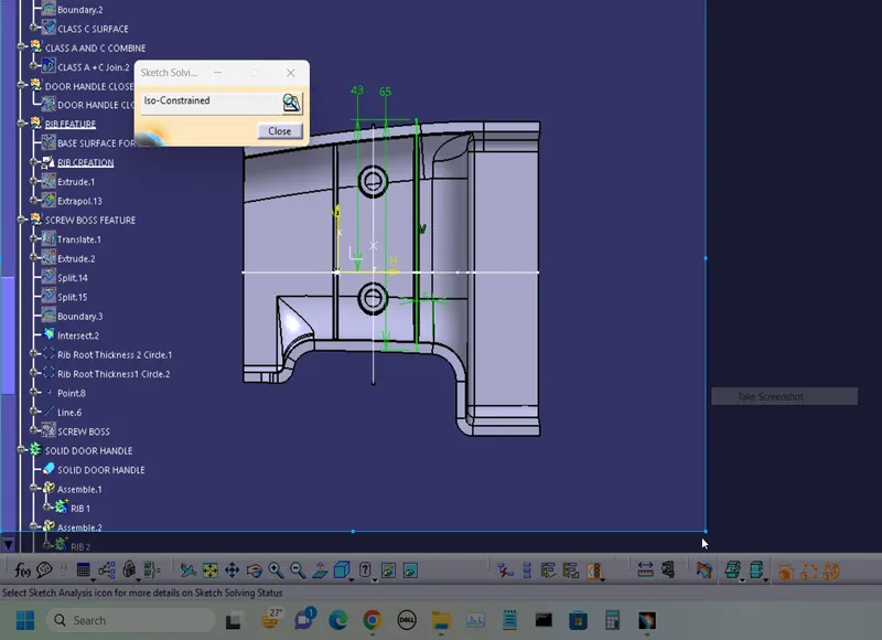
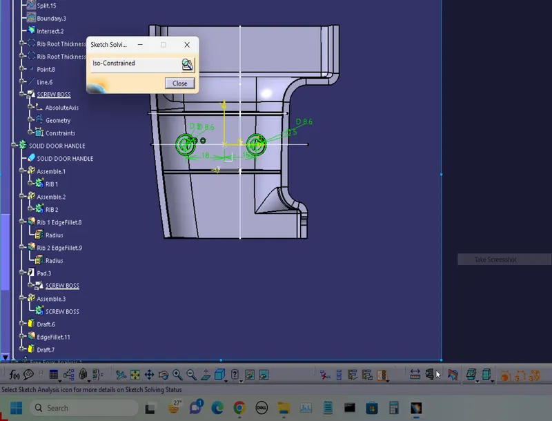
1. RIB DESIGN
- Take the support of extracted surface and choose the XZ plane.
- The thickness of the rib wall = 0.5x wall Thickness.
- Height of rib wall <= 5x wall thickness.
- Rib draft angle per side = 0.5 degrees.
- Minimum thickness at =tip 0.75 mm.
- Radius at the root of the rib = 0.25 maximum.
- Rib spacing = 3:1
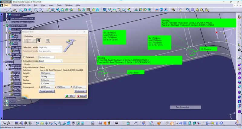
RIB ROOT THICKNESS ANALYSIS
2. SCREW BOSS DESIGN
- Let us consider, we need the M6 bolt screw boss so the Screw boss hole = 5mm
- The wall thickness of the screw boss per side = 0.6x body thickness
- Outer Diameter of screw boss = Screw boss hole+ 2x(wall thickness of screw boss)
- Height of screw boss < 3x (Screw boss hole)
- Fillet radius maximum = 0.25 mm
- Draft angle per side = 0.5 degree
3. DETAIL REPORT ON DRAFT ANALYSIS RESULT AND IMAGES
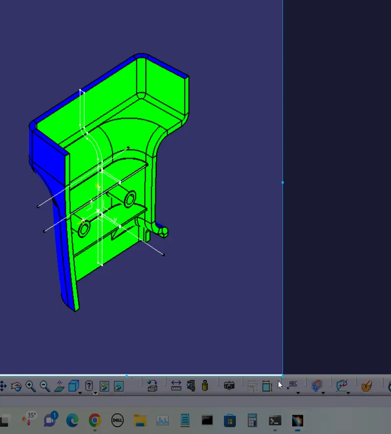
CLASS A SURFACE DRAFT ANALYSIS ON 3-DEGREE DRAFT
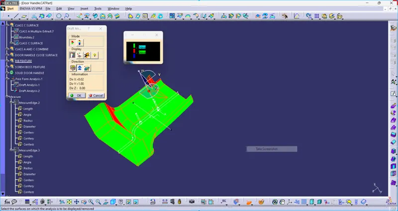
NOTE: THERE IS CLASS A SURFACE FAULT SO WE ARE UNABLE TO PREDICT THE EXACT TOOLING DIRECTION AND DRAFT ANALYSIS.
- Screenshots of the solid model in various orientations
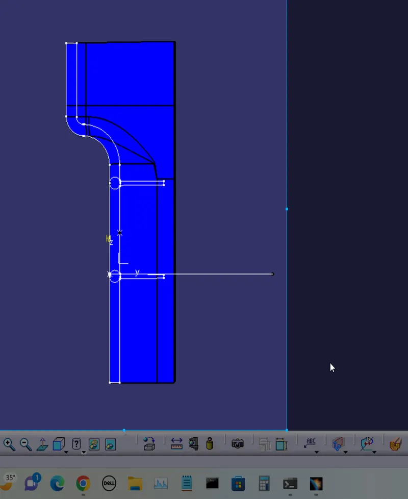
FRONT VIEW
SIDE VIEW
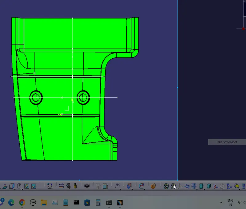
TOP VIEW
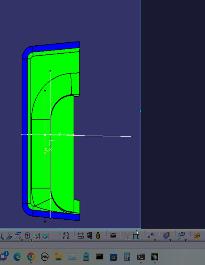
ISOMETRIC VIEW
- REPORT
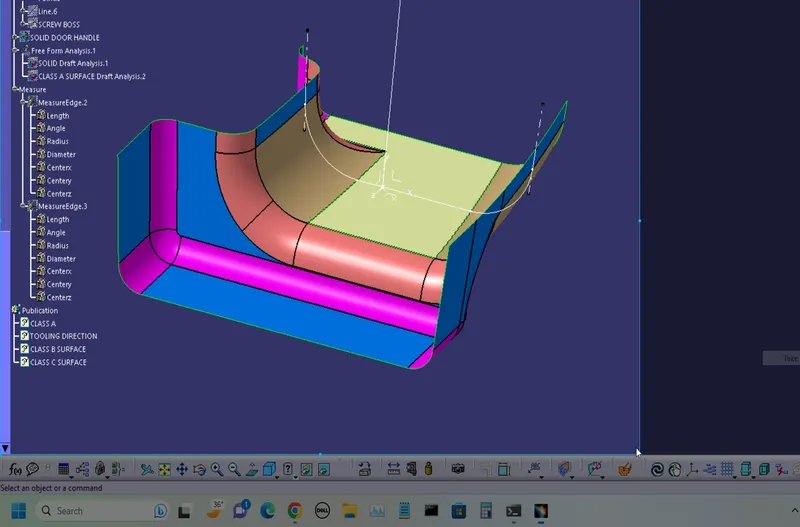
1. TOOLING AXIS CREATION
In the door handle project, we have used the bisection method to create tooling direction while we can use the normal to surface tooling axis also but both results will be the same.
- Extract flat surface from class A surface.
- create the midpoint (origin) on the extracted face.
- select the intersect and touch the class A and the XY plane, A intersect line will create.
- create the tangent line at both ends of the intersecting curve.
- choose line command select bisection method then select the bother side extended line and then touch the origin.
- now tooling direction has been created.
2. Draft analysis
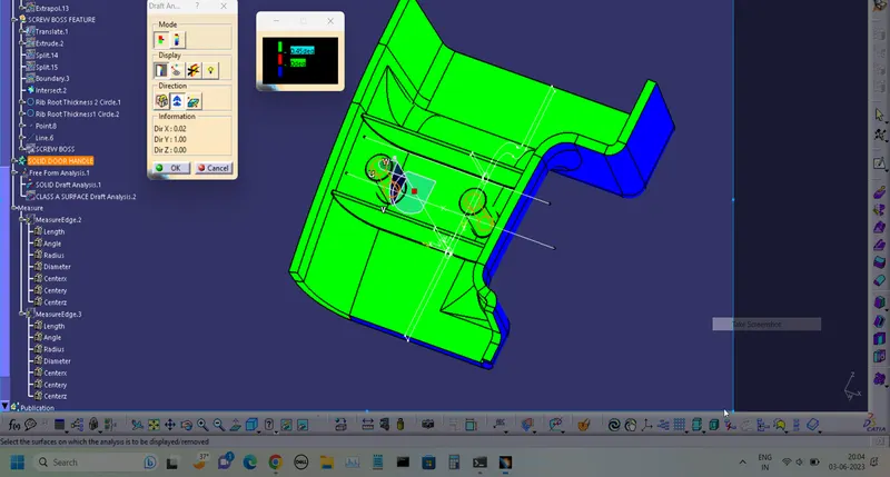
- Select the Feature Draft Analysis
- click the part and define the tooling Direction
- Green Side is showing that the part will be made according to the Draft Angle which is 0.5 degrees and there will no erosion between the Tool and Plastic parts.
- HERE WE HAVE TAKEN 0.45 DEGREE DRAFT ANALYSIS DUE TO 0.5 DEGREE DRAFT ON THE RIB AND SCREW BOSS.
- The blue side is showing a negative Draft angle (interference) or it is impossible to draw the part according to the draft angle.
4. FINAL PLASTIC DOOR HANDLE DRAFT ANALYSIS
NOTE: HERE WE HAVE TAKEN 0.45 DEGREE DRAFT ANALYSIS DUE TO 0.5 DEGREE DRAFT ON THE RIB AND SCREW BOSS
There are some errors in the Class A surface because we have taken the bisection method, normal to surface and other methods to develop the Tooling direction. but the proper draft did not get into the 3-degree draft.