Week 10 - Challenge 1- Attachment Feature Creation (Ribs & Screw Boss)
Attachment Feature Creation (Ribs & Screw Boss)
Aim:
To create the attachment features RIBs and Screw Bosses for a given drill handle concidering by the design rules.
Objective:
- Design of ribs for Drill Handle following the design rules
- Rib root thickness analysis should be carried out.
- Design of Screw Boss for Drill Handle following the design rules.
- To create the
- tooling Axis and Performing draft analysis on the final component.
Drill Handle:
Tooling Axis:
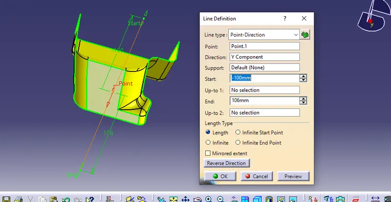
In plastic design injection molding the Tooling Axis is the most important criteria. The tooling axis along to the core and cavity area, also the component ejecting ways of the core and cavity is most common in tooling direction only. For creating the tooling axis in this drill handle is differnt and very ease with comparing to the previous plastic component design.
Here first extract the flat surface and created the point the option of point on surface to the extracted surface and select the zero point.
Class A:
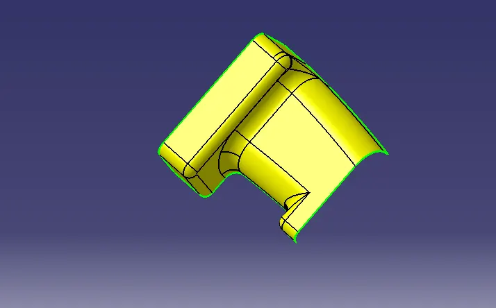
Class A surface is the aesthetic skin data for the automotive part designing and curvature surface to represent the main component.Befor proceed with A surface to analys the Draft angle, if get any mis-match surface reconstruct the A surface.
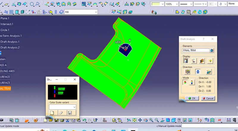
Draft Analysis Class A
Draft analysis is the main requirments in plastics Design. If the draft angle is less than 0 degree, the part or component and tool is to be damaged in mass production. Also the molding part would not eject from the core and cavity. So the drafting analysis to find out the lesser angle are by the colour variation.
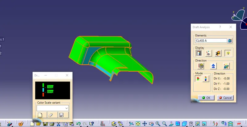
Above 3 - Green
0 to 3 - Blue
< 0 - RED
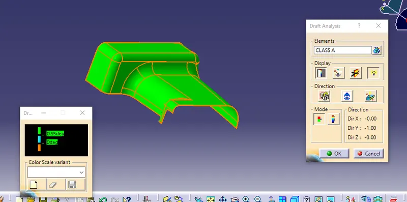
Here class A surface not clera the 3 degree draft analysis but its clear on the 0.95 degree draft as shown in below picture.
Class B surface:
The Class B surface also creating new method comparing with previous challenge. Here we directly offset the class A surface to the total thickness of close body to inward direction.
Thickness of the component to be 3 mm
So offset the class A to 3 mm inward, inthis case fillets are showing some error. Because of the inward offset the fillet will be reduce.At this moment we reconstruct the B surface with respect to the A surface.
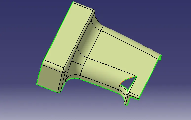
So using multi section surface command and create the surface which is in the missing fillet area. Then spilt from the offset.1 and using join with the option of sub element to remove to the remove fillets and extracted surface from the offset1.
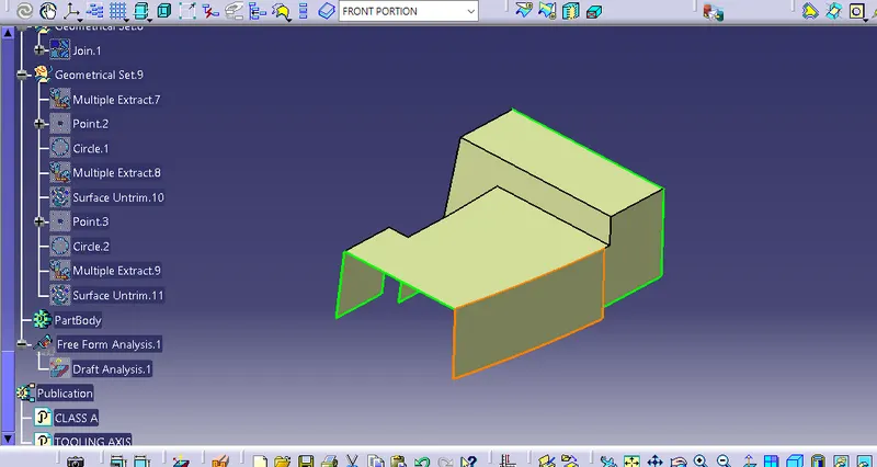
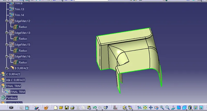
Then trim with the extracted surface to the all flat extrapolated got the B surface and give the all fillets with respect to class A.(Here consider the offset is inward direction so the fillet radius will change with respect to the thickness of close surface.)
Class C surface:
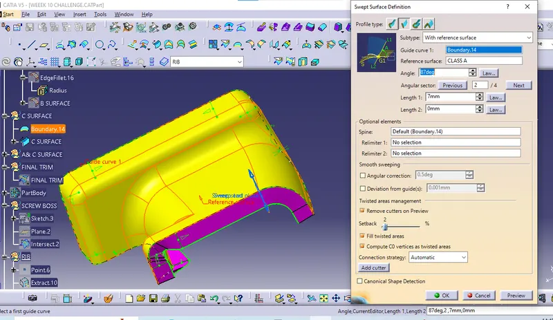
For creating the C surface draw a boundary to the class A surface edges and sweep the edges with draft direction and with reference surface at the angle of 87° .
Class A and Class C:
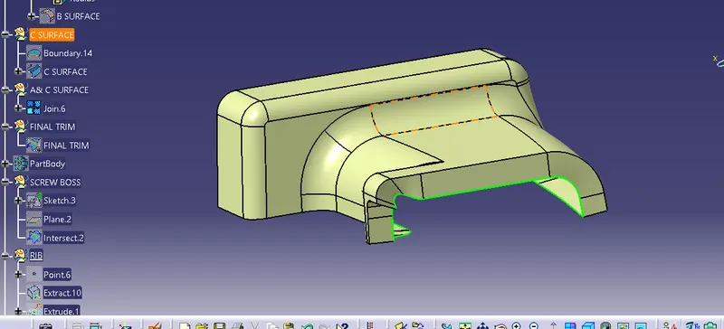
To join the class A and Class C surface by using join command.
Final Trim:
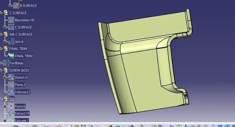
To trim the Surface (A+C ) with the B surface.
Close Solid Surface:
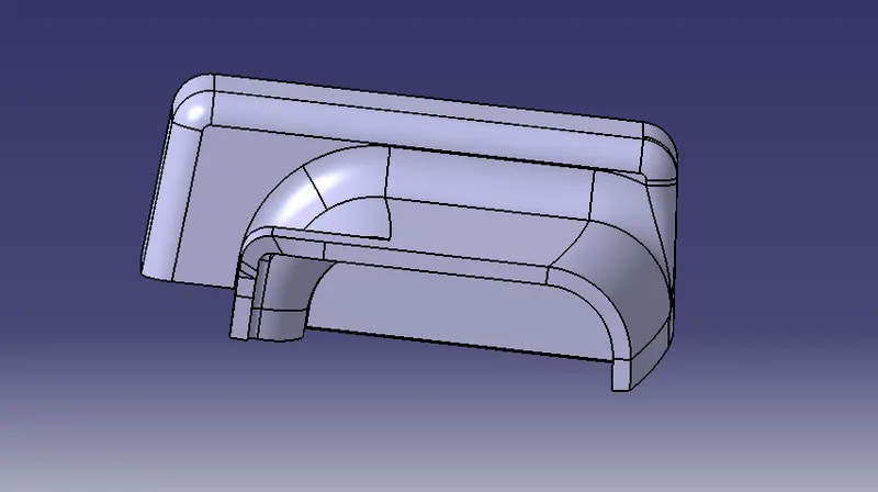
START -> MECHANICAL DESIGN -> PART DESIGN -> SURFACE FEATURE -> CLOSE SURFACE
Rib Design Rules
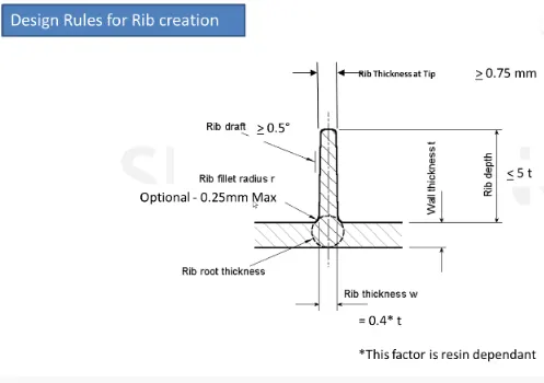
- Draft: 0.5 Degree per side (minimum)
- Thickness of ribs: 40% of wall thickness
- Height: ≤ 5 times the wall thickness
- Spacing (for more than 1 rib): 3:1- steel height/width ratio (maximum). h/w =3 or2(preferred) where h is the height of the rib and w is the space between two ribs.
- Minimum thickness at the tip: 0.75
- Radius: 0.25mm max
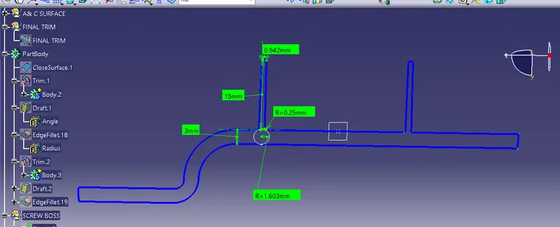
- Rib root thickness should not be more than 30% of the wall thickness.
Rib Design:
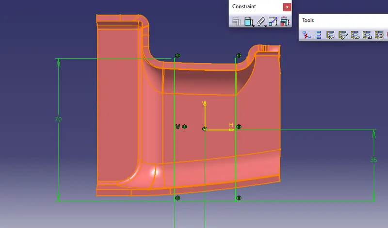
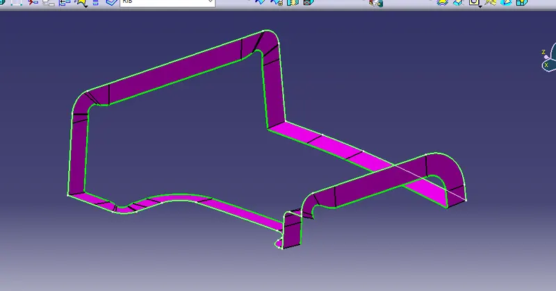
- Create the reference plane on the Solid surface by extract the flat surface.
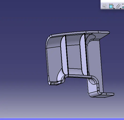
- Create positioned sketch for the ribs and extrude the sketch with reference to the tooling axis and thicken the extrude face with reference to the tooling axis.
- Perform union trim of ribs with the drill handle part body
Rib root thickness Analysis
Screw Boss creation
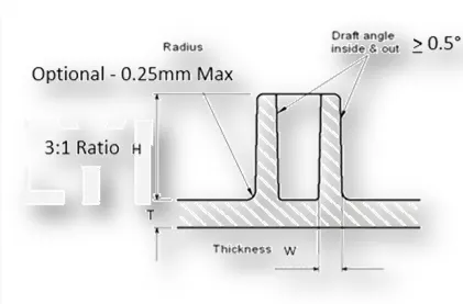
- W= 0.6*T
- Draft 0.5 Degree on both inside and outside walls of the screw boss.
- Height to diameter ratio – 3:1
- Radii(fillet) – 0.25mm(maximum)
- Boss Gussets must meet rib guidelines
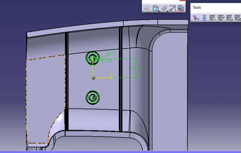
- Create sketch of screw boss and extrude with reference surface to the tooling axis.
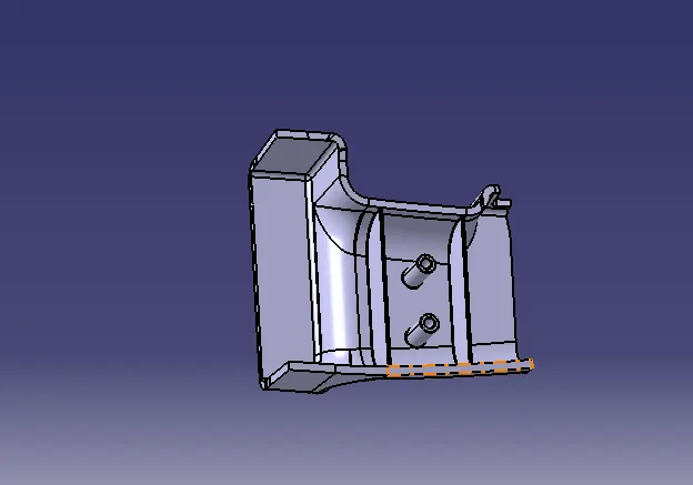
- Thicken surface and Using the Boolean operation union trim the boss gusset with the main body.
Boss Intersection Analysis
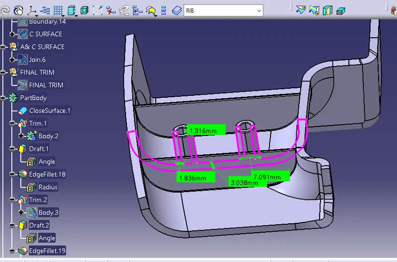
Thickness 0.6 * 3 = 1.8 mm
Different Views:
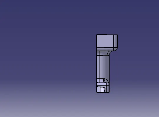
Front View
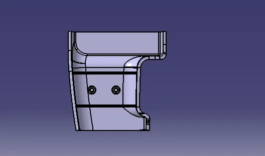
Side View
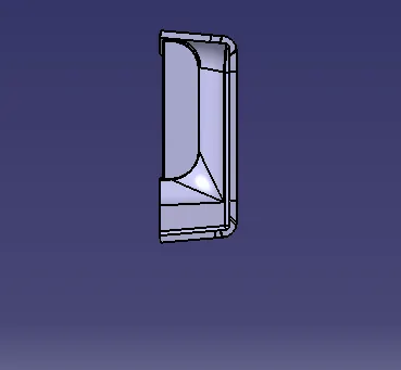
Top view
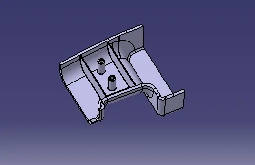
ISo View
Final Close Body Draft Analysis:
Procedure for performing the draft analysis are as follows
- Change the view mode of the component into customized parameter mode and then select the shading option as material mode.
- Then open the featured draft analysis tool from the insert menu -> Analysis.
- Then click the compass and drag the axis to define the current drafting direction to tooling axis.
- Then lock the draft direction and perform draft analysis by pick the component.
- The green colour shows the positive daft tooling direction and the given surface passes the draft analysis.
Above 3 - Green
0 to 3 - Blue
< 0 - RED
The final draft analysis the close surface clear by the draft angle.In Plastics design 3 degree is the minimum draft angle to drafted over the area which is permissible at the injection molding manufacturing area.Here the class A surface not clear 3 degree draft, so the final close body also not clear in 3 degree draft.
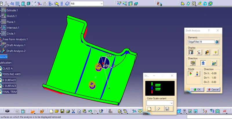
But Here also same draft angle of class A 0.95 degree is cleared
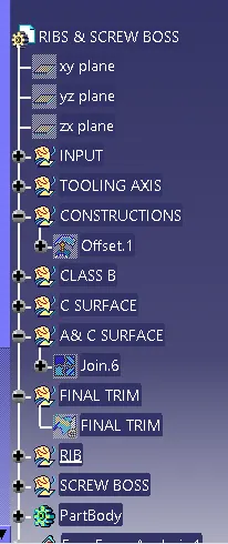
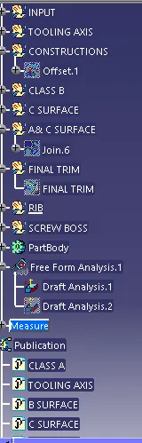
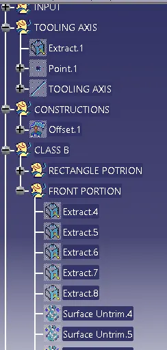
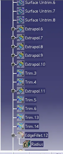
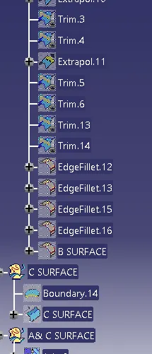
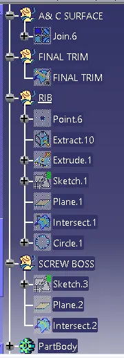
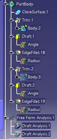
Tree Structures:
CONCLUSION:
Finally the attachment features Design and drfat analysis was done successfully.