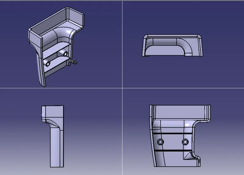
Week 10 - Challenge 1- Attachment Feature Creation (Ribs & Screw Boss)
Aim: Create the rib and screw boss the Drill Handle considering the design rules and also Class-B and Class-C surface creation.
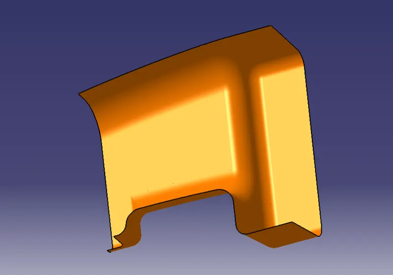
Fig: Drill handle Class-A surface.
Tools used:
- Boundary
- Jion
- Multiple extract
- Bisecting line
- Trim
- Surface offset
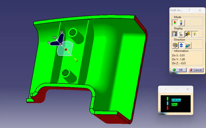
- Draft analysis
- Intersect
- Surface sweep
- Close body surface
Description:
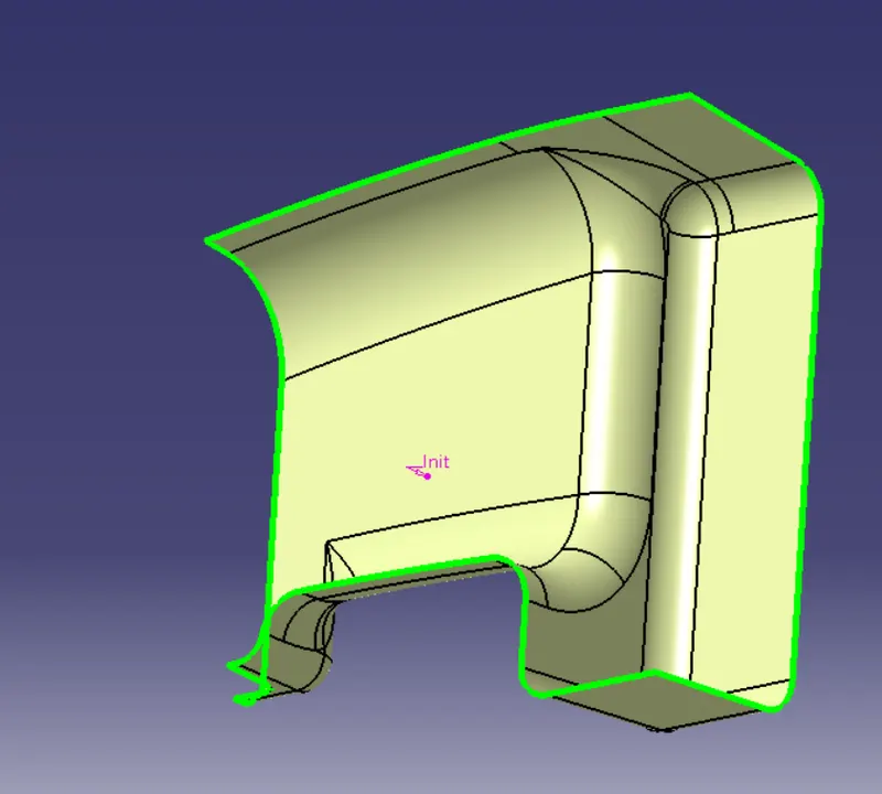
First of all, Check for gaps between surface for that join or boundary command operation use. if there any gap between the surface a maximum tolerance of 0.003mm.
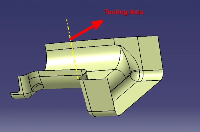
Creating Tooling Axis:
- The Tooling direction is basically the direction that the mold pulls a part. The mold is built in two separate pieces basically. You have a cavity side and you have the core side. The core pulls a part from the cavity and that the dye line or Tooling Direction.
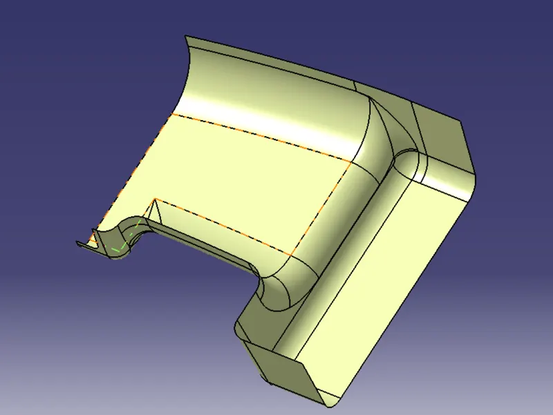
Class-A surface:
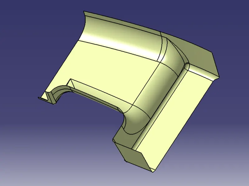
Class-B surface:
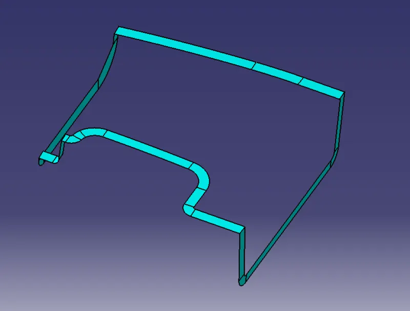
Class-C surface:
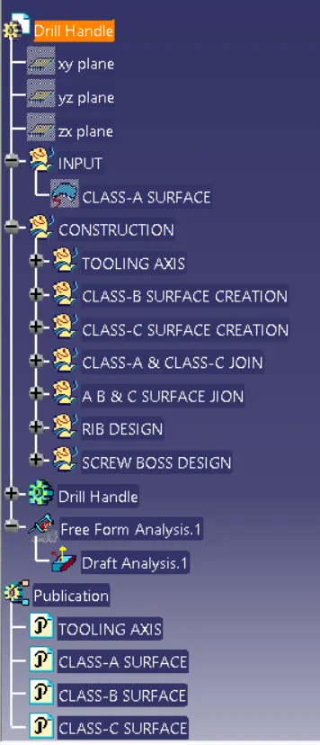
Rib Creation:

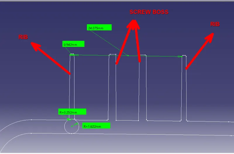
Screw Boss Creation:
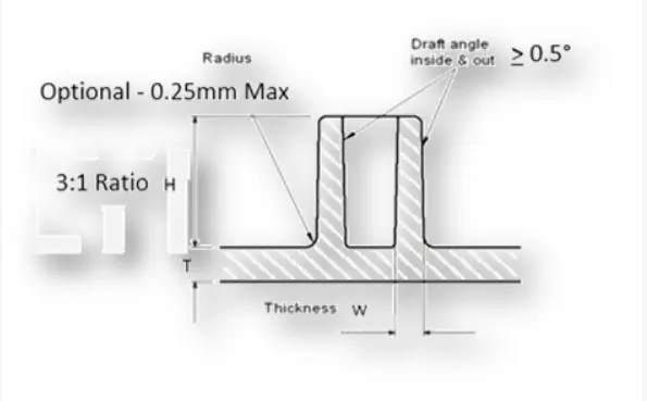
General Guidelines for Bosses: -
- Draft 0.5 degrees on the walls of boss.
- Thickness typically 40% of the nominal wall of the boss.
- Height to Diameter Ratio 3:1
- 0.25mm maximum radius.
Draft Analysis:
3D VIEW MODEL: