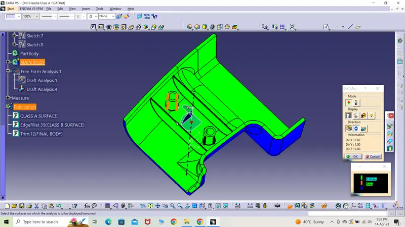
Week 10 - Challenge 1- Attachment Feature Creation (Ribs & Screw Boss)
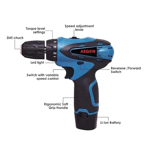
The drill handle is the part that is used to hold the drilling machine. It is made up of plastic and is produced by injection molding. There is a skin surface with the name A class and a B class is created that is equal to the thickness of the part. The part is joined with a wall which is the class C surface. The part is created into a solid part. The part needs to be strong and is joined with other panel on the either side. So, the B class surface has ribs and screw bosses for the same purpose as mentioned earlier.
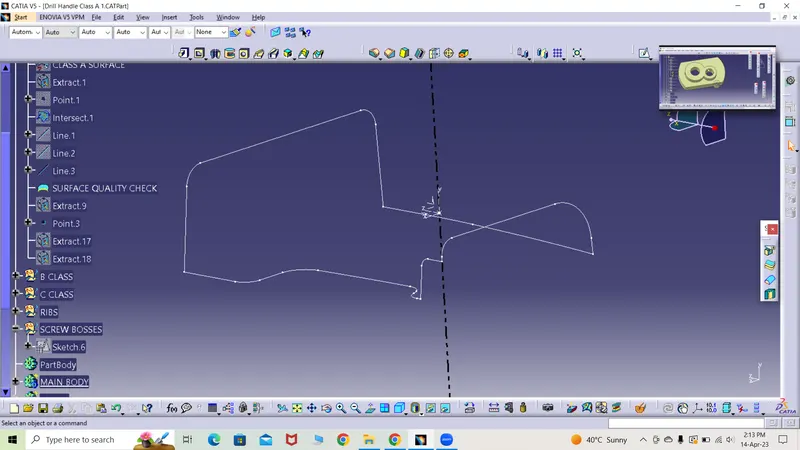
1) The A surface was given and so the next step was to check for the surface quality of it. It was done by creating the boundary from the same surface. The surface looked continous and proper to carry out the further processes.
2) The surface was then checked for draft analysis. There are three methods to carry out draft analysis which are listed below with the results.
Point direction
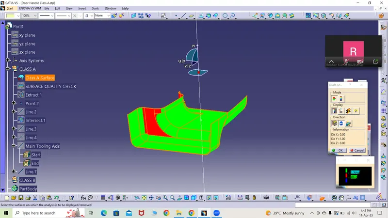
Normal to surface
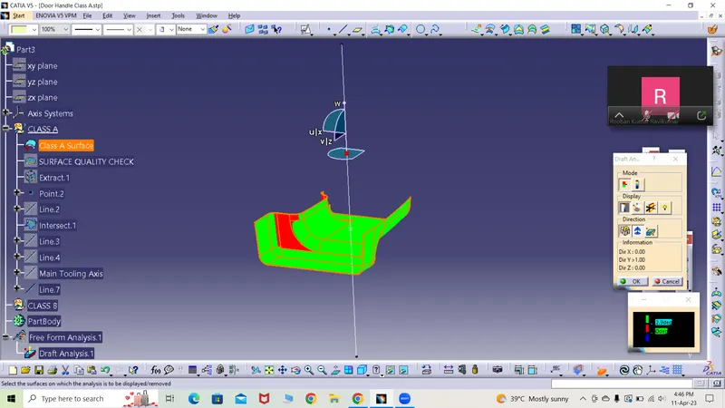
Bisecting line technique
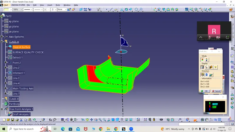
3) A small portion failed with all the methods and so it was concluded that surface A had some finishing issues. The report could be prepared and given to the surface creators to repair the surface only then it would pass the draft analysis test.
4) To convert the given surface into a solid part, simply create class B surface which was done by selecting the class A surface and then offsetting the same to 2.5mm which was the desired thickness of the final part.
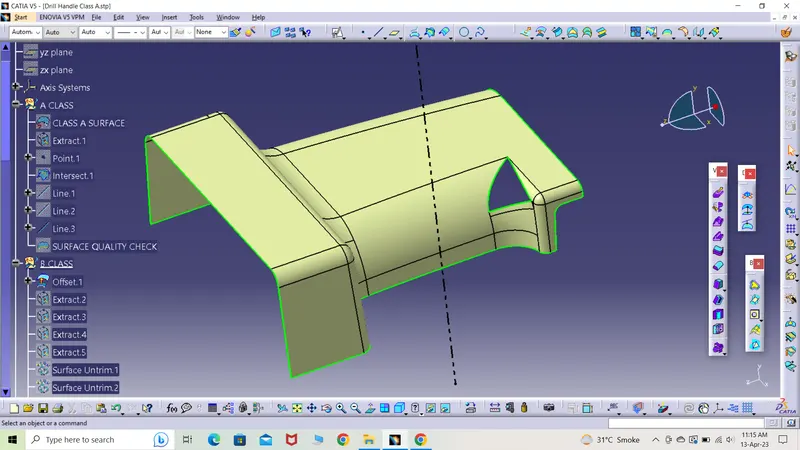
5) It was observed that there was a patch with no surface and that was needed to be created by extracting the flat surfaces.
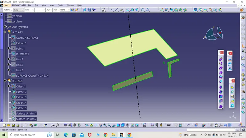
6) One by one the flat surface from class A surface was extracted and then untrimmed, extrapolated.
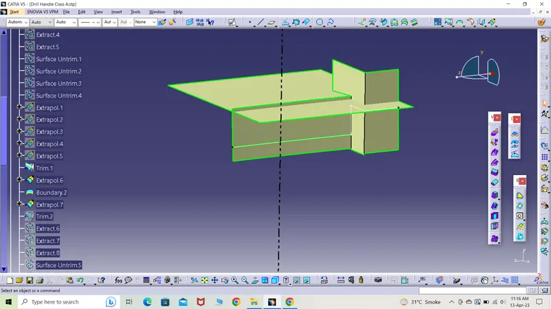
7) The surfaces which were intersecting were trimmed finally to get the block 1(front portion).
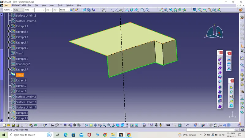
8) In the same manner, the rear block was created.
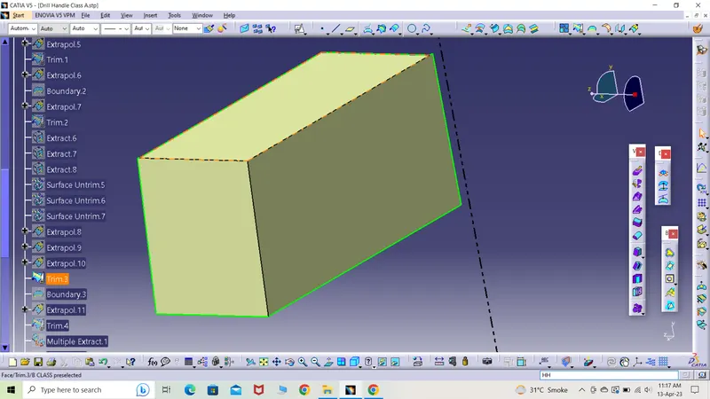
9) Block 1 & 2 were extrapolated and trimmed to get the desired surface.
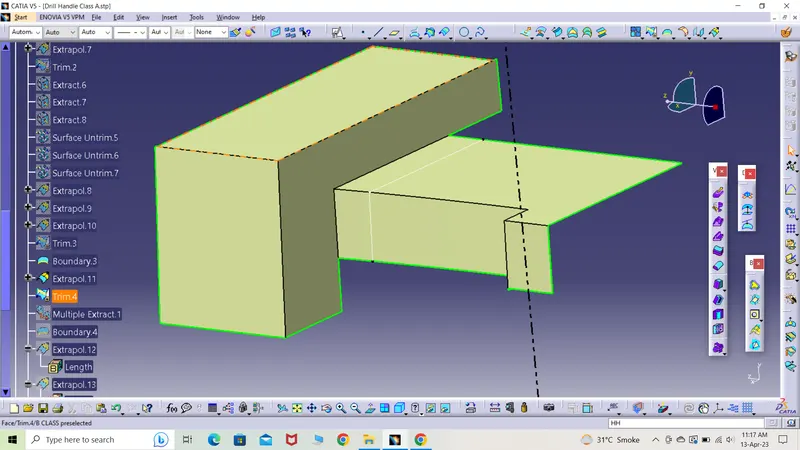
10) The right side of the part surface was curved which was multi-extracted and the same technique was used to create the whole surface.
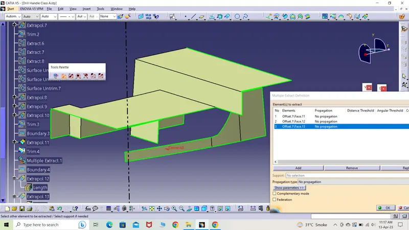
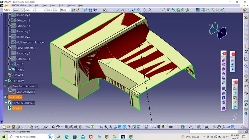
11) The same surface was later filleted one by one as it was a very complex process and required to proceed in a particular manner by selecting a particular edge at a time.
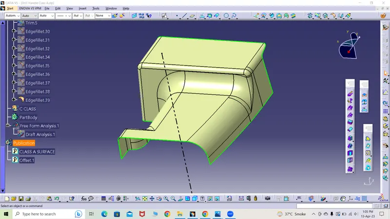
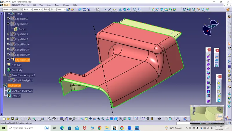
12) The surface was completed and checked by taking class A as reference and also the filleted class B surface.
13) By taking four different boundaries, swept command was with reference surface and draft direction for the surfaces where 90 surface was to be created and 3 degree draft to be created respectively.
14) The four edges were extrapolated and then trimmed to make it a single surface i.e. class C.
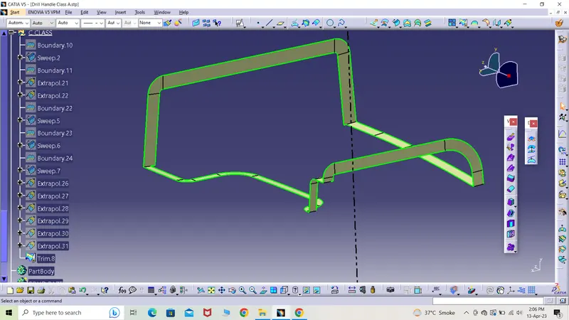
15) The class C surface was joined with class A to give surface A+C as a single surface.
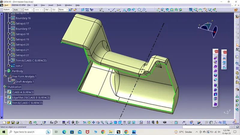
16) The same class A+C surface was trimmed with class B surface and the final body was obtained.
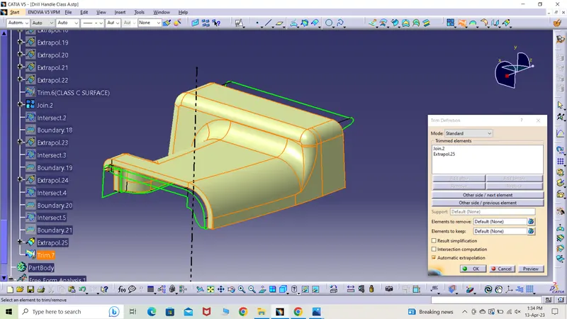
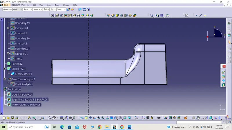
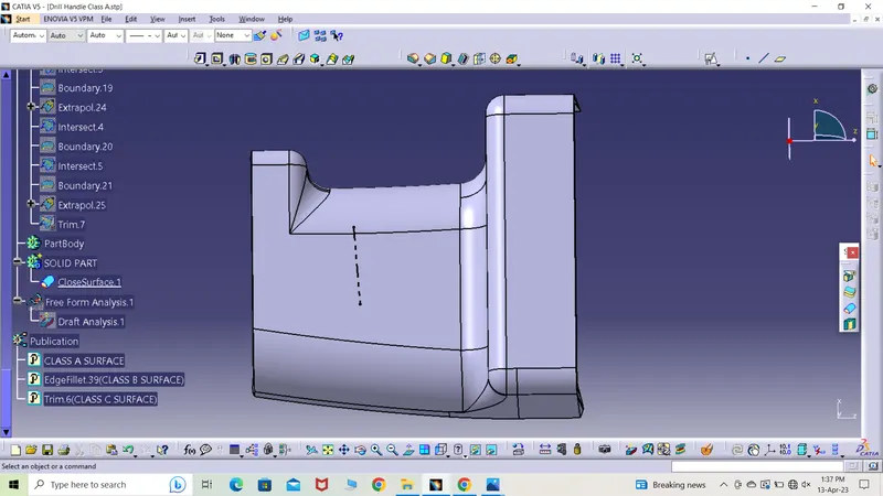
17) The same surface was a hollow one and by entering the part body mode, it was converted into a solid body by selecting close body surface. The part is shown in different views.
ISOMETRIC VIEW
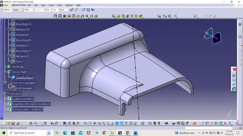
SIDE VIEW
FRONT VIEW
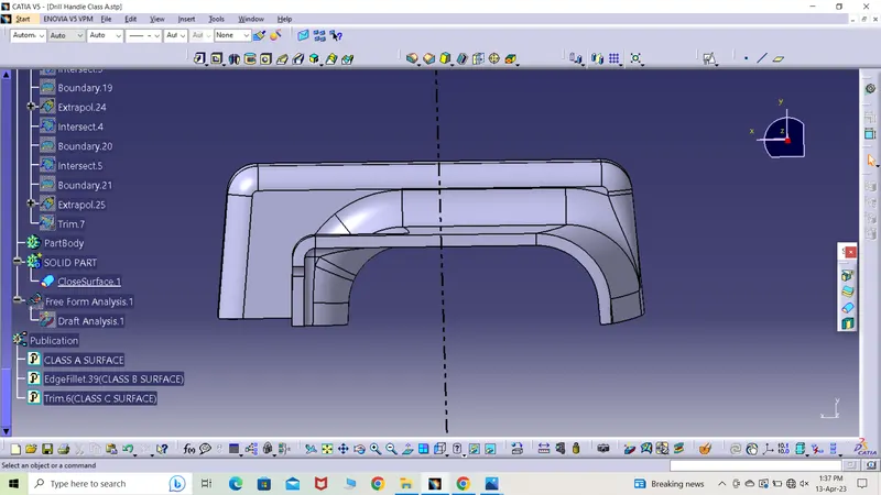
TOP VIEW
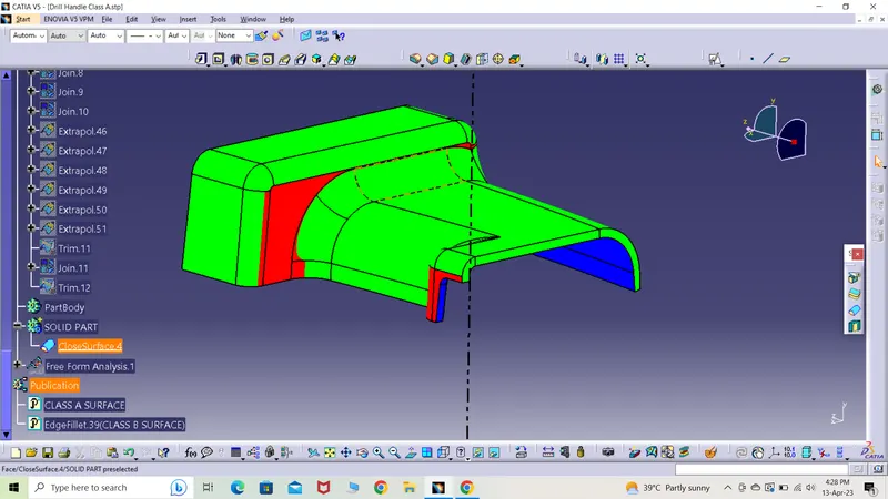
18) The same body was checked for draft analysis by following the same process as mentioned above.
19) To create the ribs, the sketch was created and was iso-constrainted to fix the sketch.
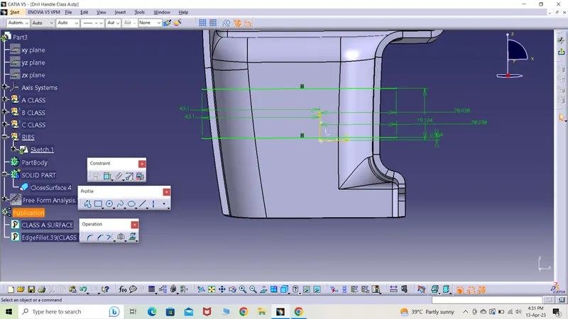
20) The same sketch was considered to create a solid body by using the padding option.
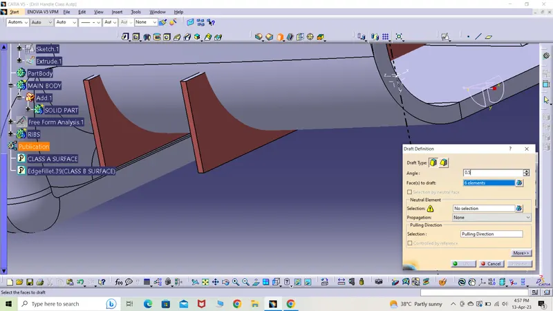
21) The same body was union trimmed with unwanted region removed to the main body and the desired rib was obtained and later filleted.
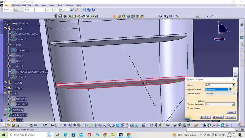
22) The same rib was recreated with a spacing of 23mm.
23) The ribs were checked for draft radius which was 0.25mm.
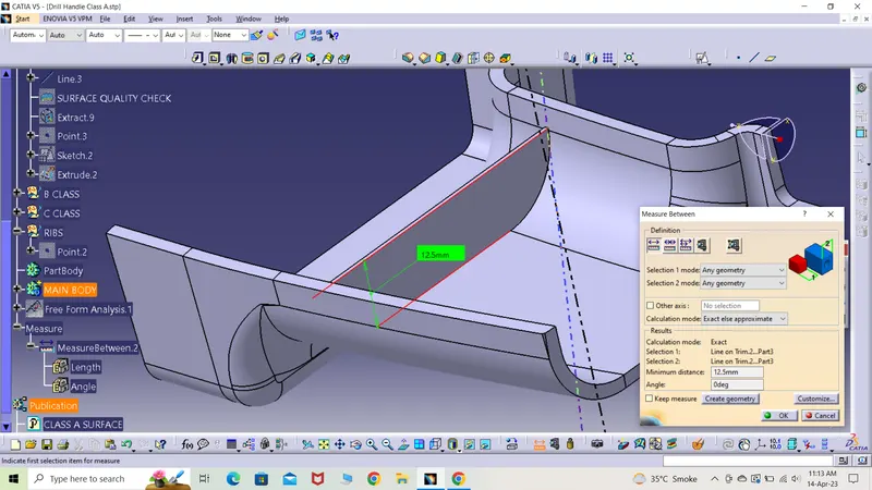
24) The thickness was given as 0.4*2.5= 1mm.
25) The spacing was given as 22-23mm.
26) Thickness at the top also passes the required value which is more than 0.75mm.
27) Bottom rib thickness was more than the thickness which were 2.68mm and 2.5mm resp.
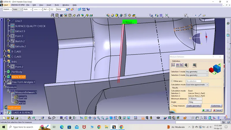

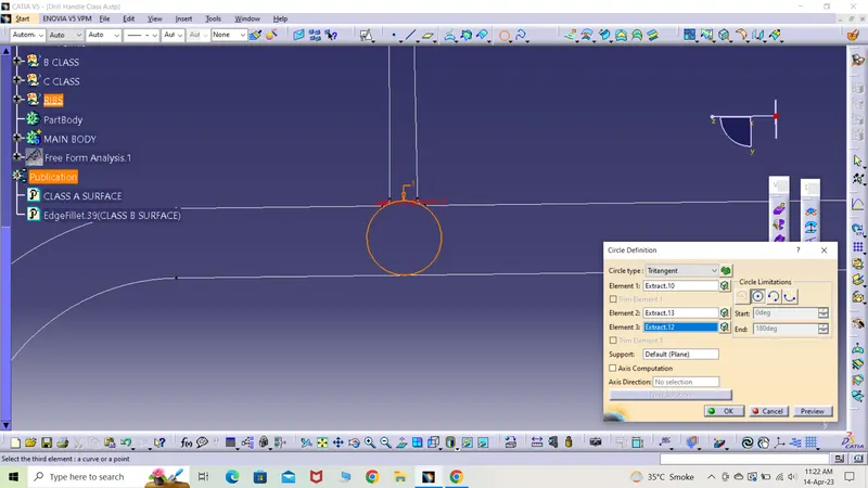
28) The screw bosses were the next part to be added to the main part. They were created one at a time.
29) The screw part could be only created by sketching the circles with iso-constrained figures.
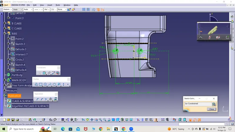
30) The same sketch was later coverted into a solid body by using padding command.
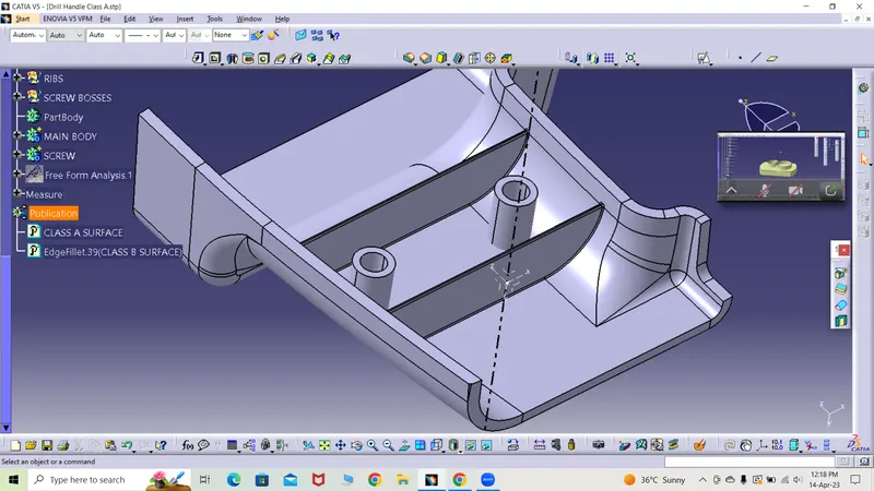
31) Another screw boss was created in the same manner and then draft and fillet were given to the same to get the desired part. They were also added to the main part by boolean operation.
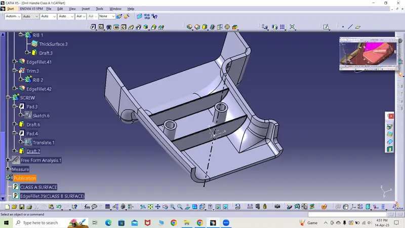
32) Screw boss ribs were also created in the same manner and drafted and filleted as per the safe design rules.
The final part was created and for a detailed analysis, the part file has been attached below.
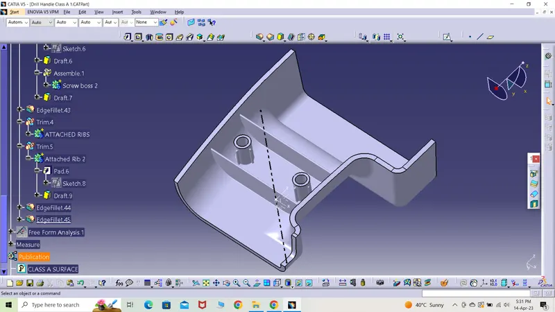
DRAFT ANALYSIS OF THE FINAL PRODUCT