Week 10- Assembly Workbench
Good day colleagues,
So,I have opened the Link for Model drawing 1 and Link for Model drawing 2 files in order to see what are my next tasks.
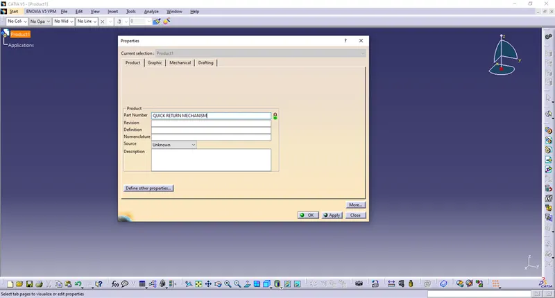
So,first Link for Model drawing 1 – after I opened it,there was one assembly QUICK RETURN MECHANISM,with 5 Parts under it.I have started with a Product that I have renamed as a QUICK RETURN MECHANISM.
Then I am designing first Body Part – BODY 1.
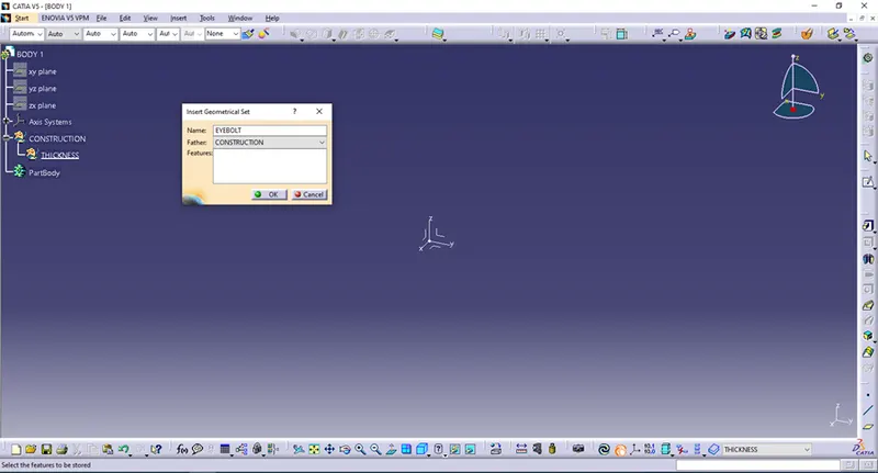
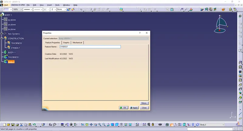
I have renamed Geometrical Set.1 as a CONSTRUCTION and under it inserted two Geometrical Sets – THICKNESS and EYEBOLT.I have also inserted two Body Parts with same name and renamed PartBody as a BODY 1.
I am designing first Feature.
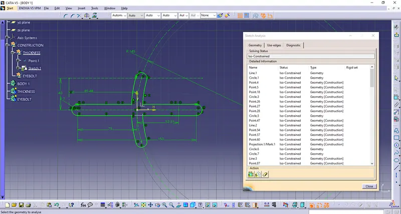
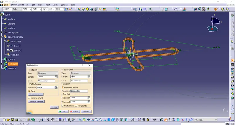
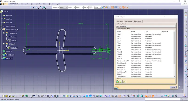
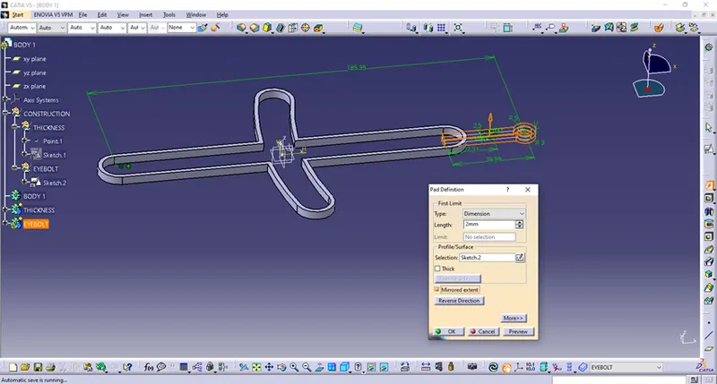
I have add fillet and joined Features,first THICKNESS and EYEBOLT with Uniontrim and then I have added it to BODY 1.
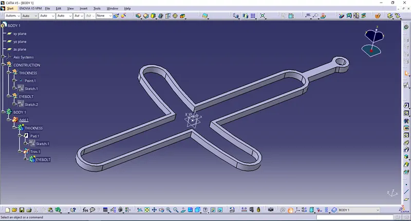
I will insert one more Geometrical Set – PUBLICATION,I will there add a pair axis for publication.
Then I will Publish all elements as shown.
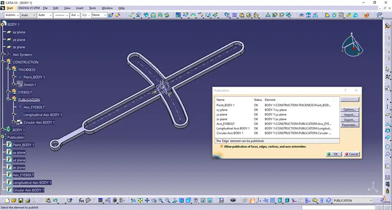
I am designing now second Part – BODY 2.
I am,as previously,renaming Geometrical Set as CONSTRUCTION.In that Geometrical Set I made basic Positioned Sketch and inserted Geometrical Set PUBLICATION.
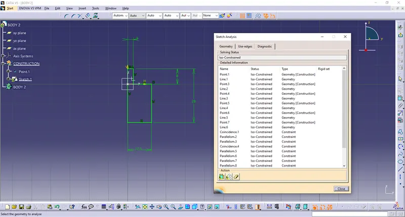
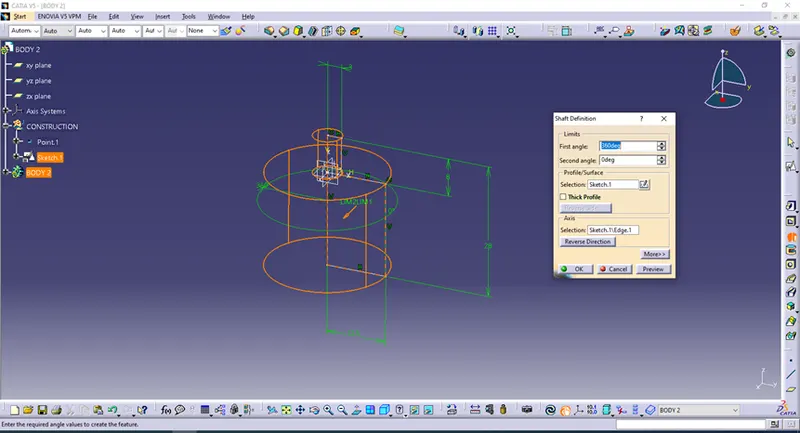
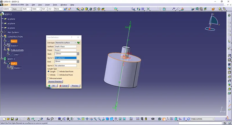
Finally I have published following elements.
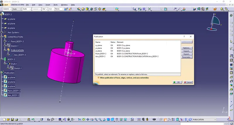
I am designing next Part – BODY 3.
I have renamed Geometrical Set.1 as previously CONSTRUCTION and made a Part as it is shown.
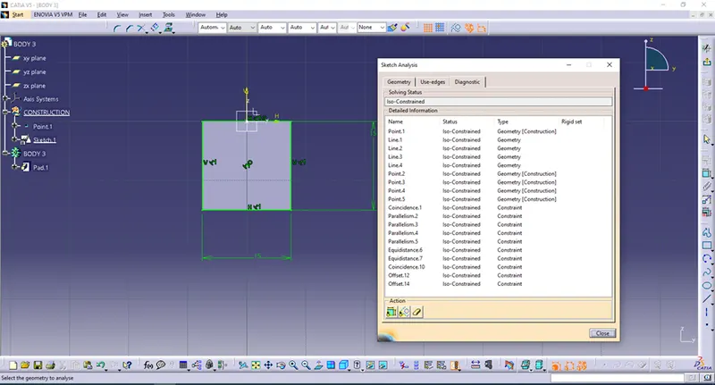
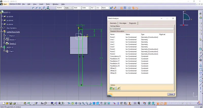
Under CONSTRUCTION Geometrical Set I have inserted PUBLICATION and there published construction elements.
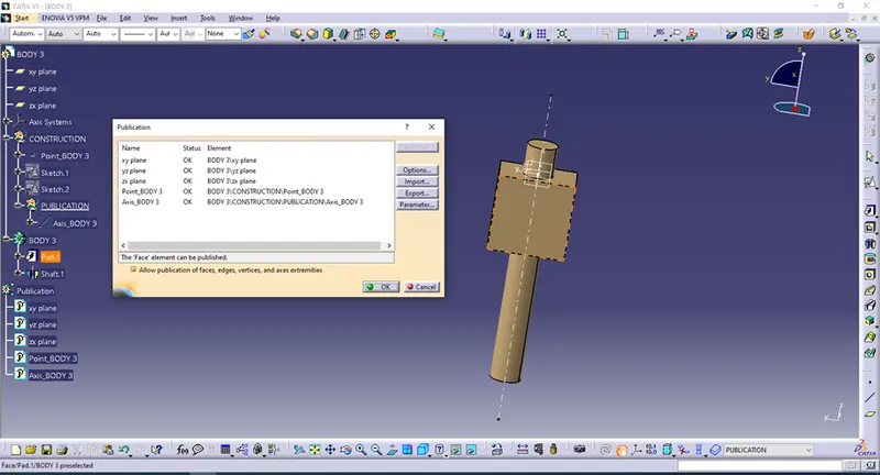
Now comes next Part – BODY 4.
I will change Part name to BODY 4 and under Geometrical Set CONSTRUCTION I will insert Geometrical Sets BASE,EYEBOLT, REMOVE,ADD.
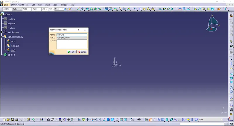
Now I am inserting and Body Parts with same names.
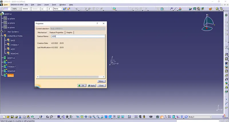
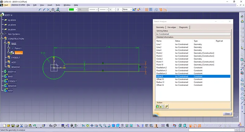
I am making Positioned Sketches under Geometrical Sets as shown on images and Solid Parts on sketches.
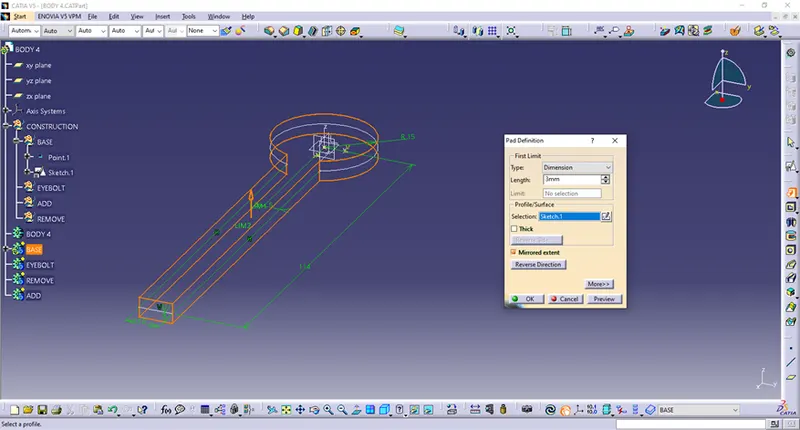
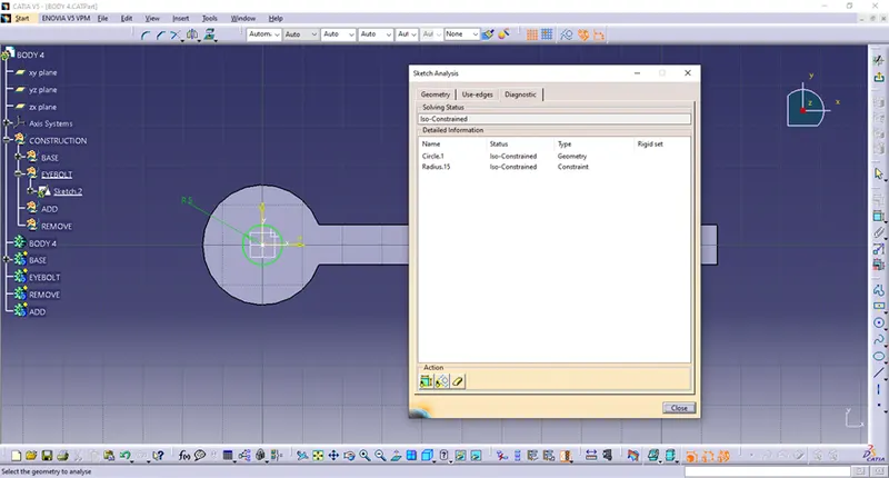
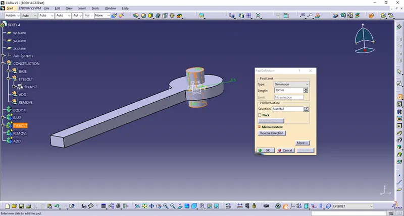
Now come last 2 features ADD and REMOVE.
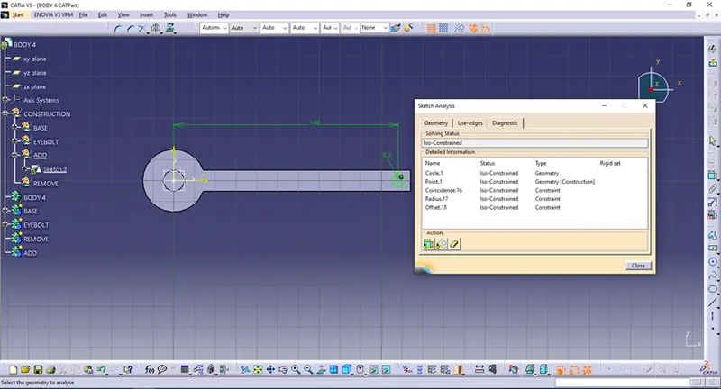
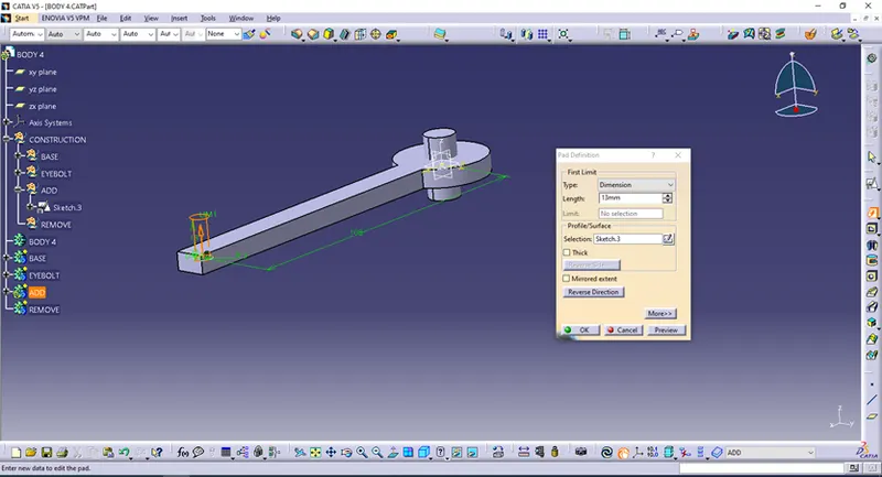
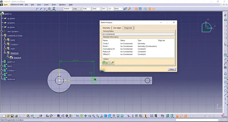
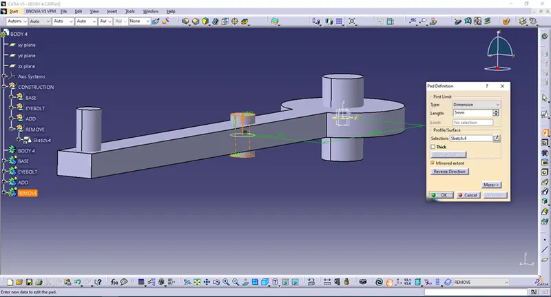
I am doing Add – Remove operations to get Solid Part as specified on drawings.
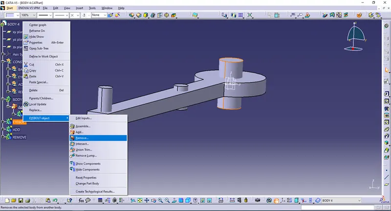
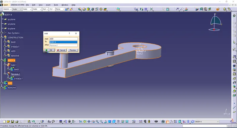
Then,I have inserted one more Geometrical Set – PUBLICATION where I will do some Axis for publication.
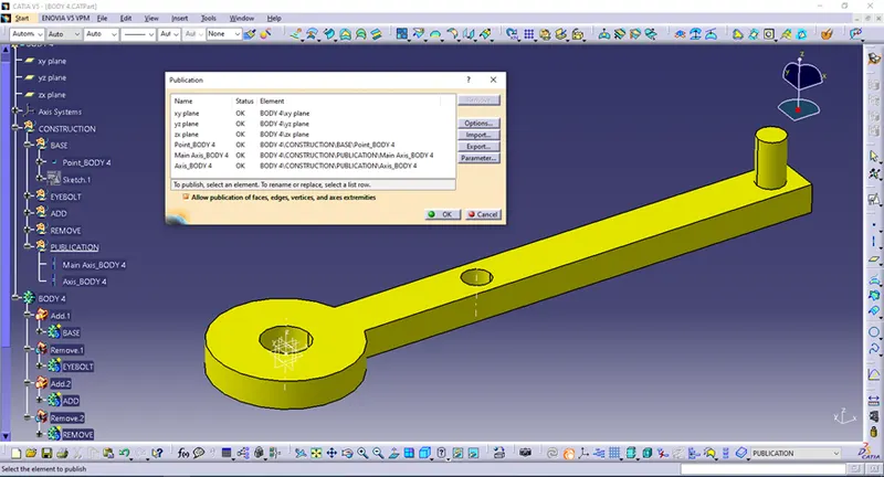
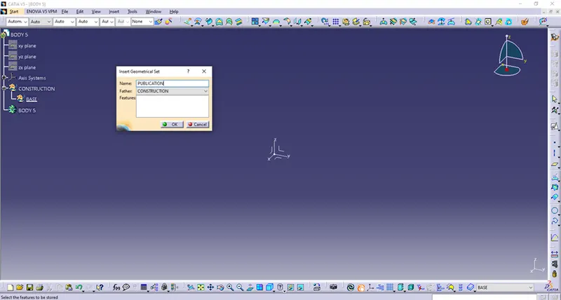
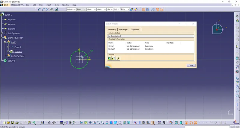
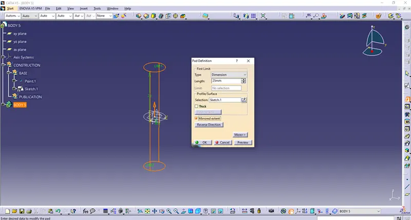
Now comes last Part – BODY 5.I have renamed Features and inserted Geometrical Sets BASE and PUBLICATION.
On that basis I have do Solid Part and published elements.
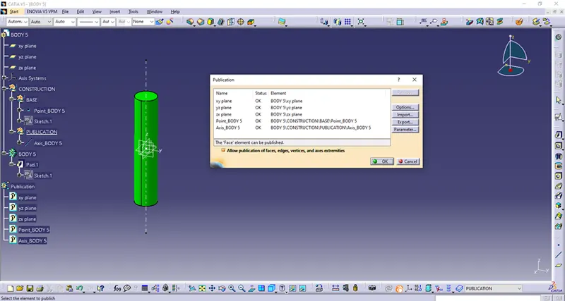
In the Product QUICK RETURN MECHANISM I am inserting componente – Parts as follows.
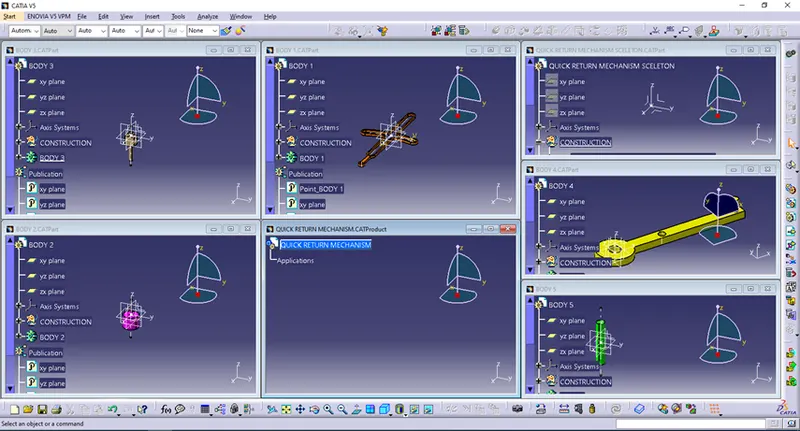
Using Drag&Drop or Insert Components options I have inserted Components under QUICK RETURN MECHANISM Product.
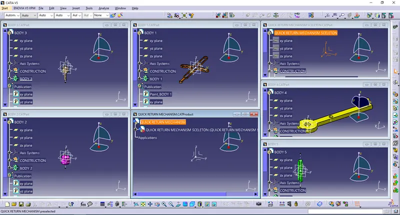
First I have inserted and fixed QUICK RETURN MECHANISM SCELETON Part.
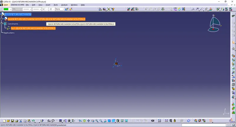
Afterwards I have inserted all other components.
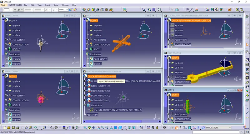
I have saved all Parts with Save Managment under corresponding directory.When saving with propagate directory option all files are saved in one directory.
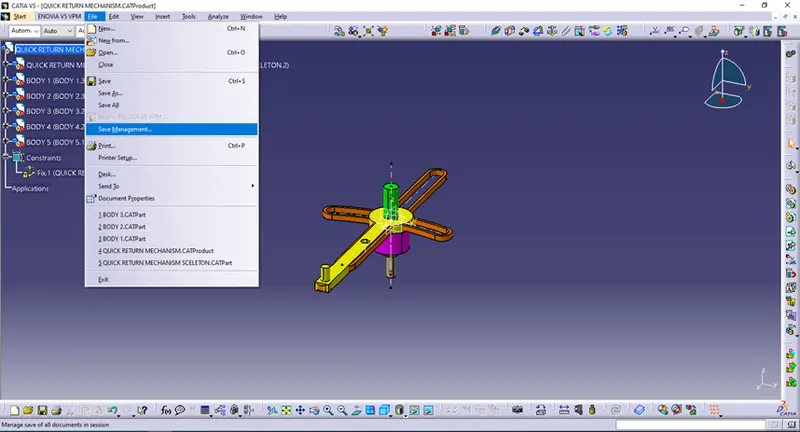
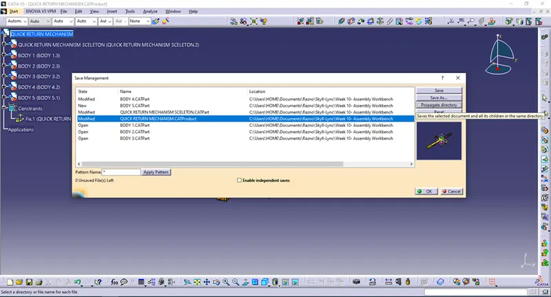
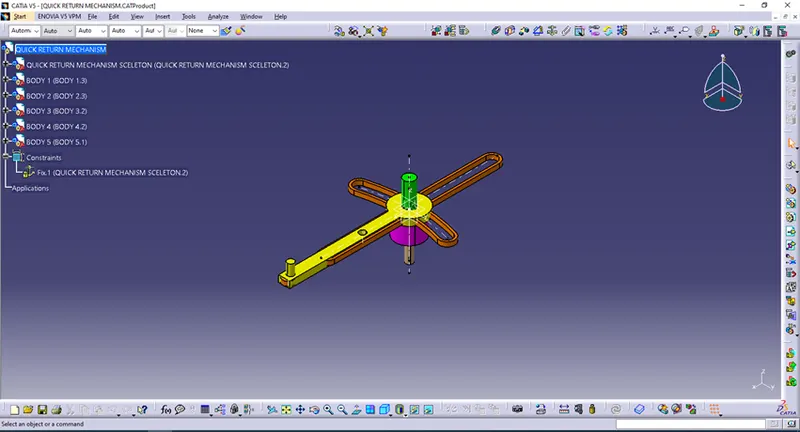
After I have saved all files I will now add constraines to the QUICK RETURN MECHANISM.First I will move Parts one from another to have a brief overview of the assembly.
With manipulation commands I have positions as shown,I have moved the parts.
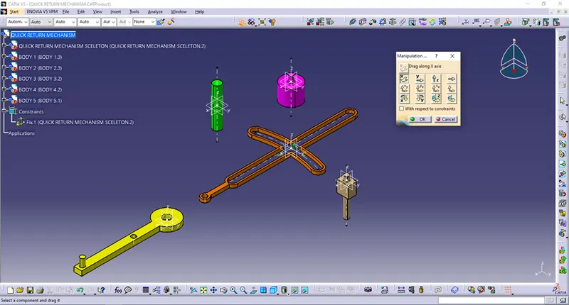
With coincidence constraines I will fix BODY 1 to QUICK RETURN MECHANISM SCELETON.
Published planes are used to make constraines quickly.
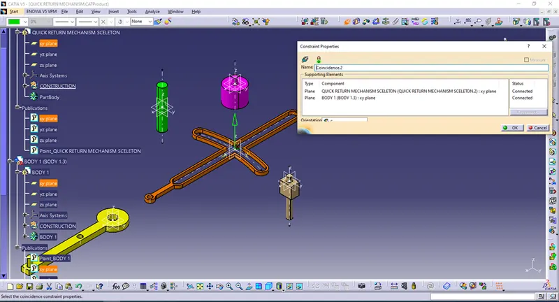
I will now make constraines between BODY 1 and BODY 2.I will once more use published planes,axis as shown.
With coincidence and offset I have fully constrained parts.
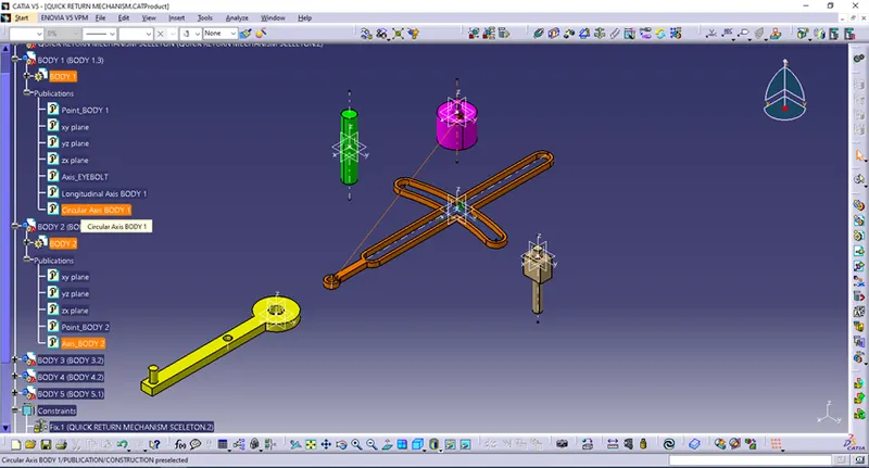
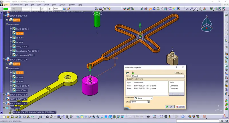
Then I have constrained BODY 1 and BODY 3.
Using coincidence and offset I have constrained BODY 3 also.
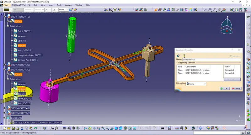
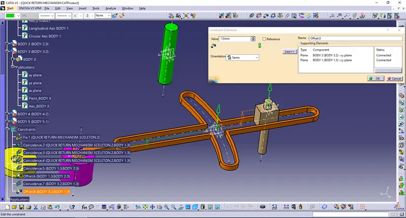
Then I have defined BODY 5.
With Coincidence and Offset BODY 5 is defined.
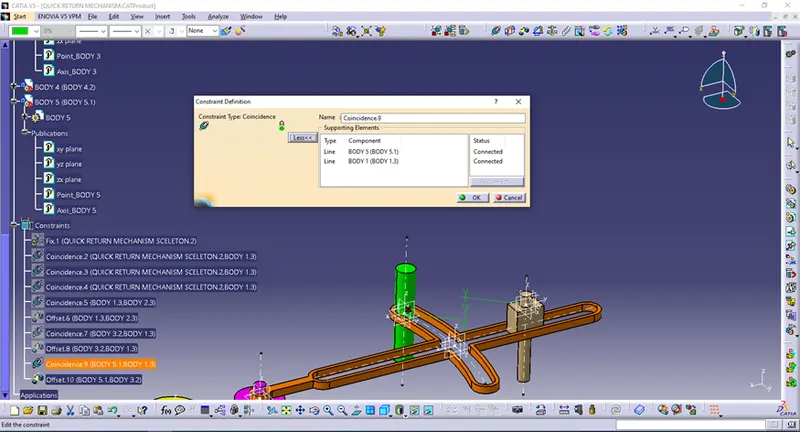
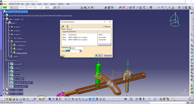
Finally I should define and constrain and BODY 4.With constaraine and offsets I have defined the BODY 4.
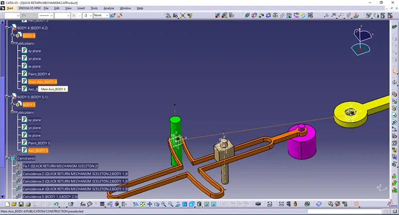
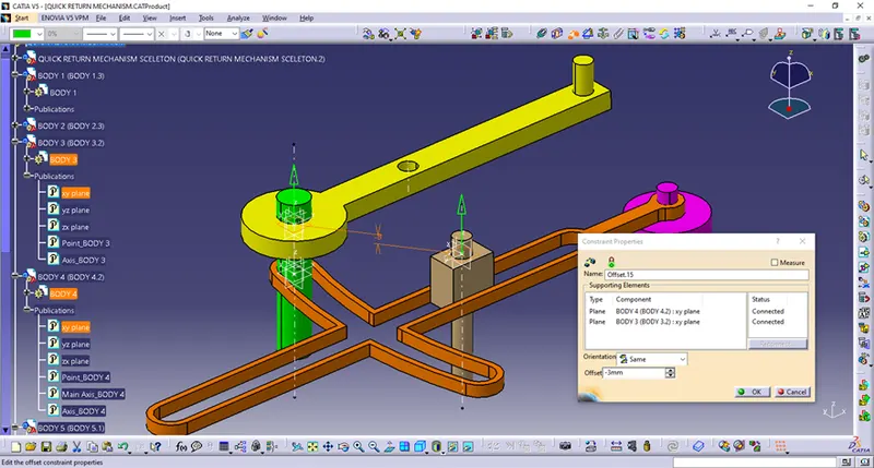
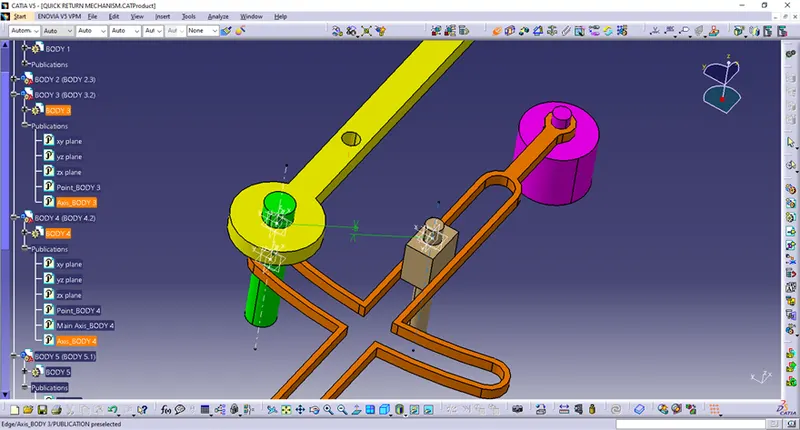
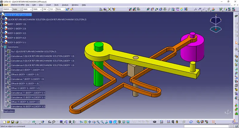
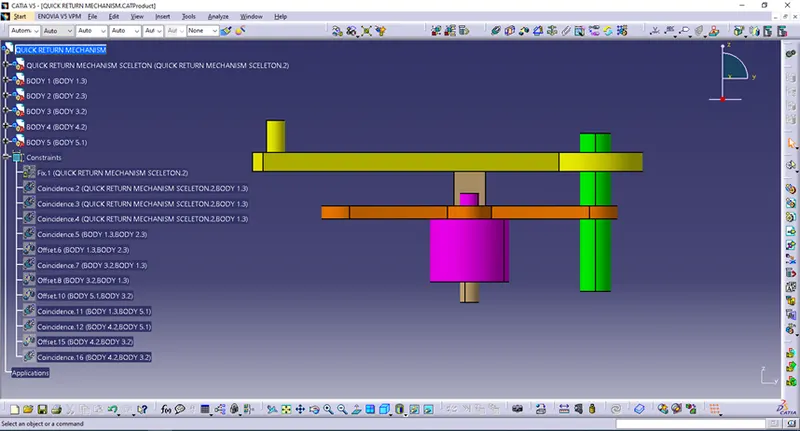
QUICK RETURN MECHANISM is constrained as it is shown on images.
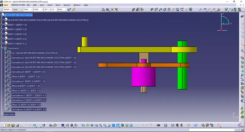
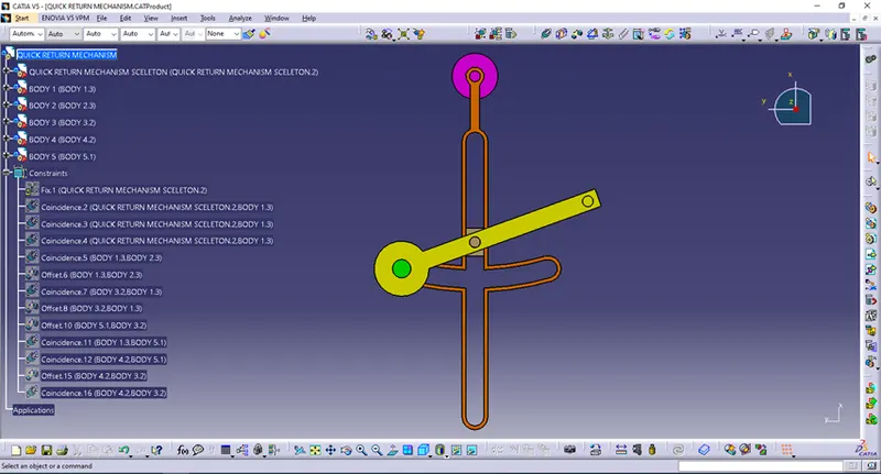
I am going to design second file received - Link for Model drawing 2 file.After I have opened the link there is assembly CV JOINT.I will open Product in assembly workbench(I will rename it as CV JOINT) and afterwards Part with a name CV JOINT SKELETON and a Part with name BODY 1.
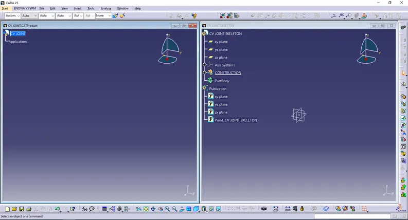
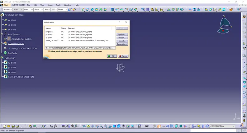
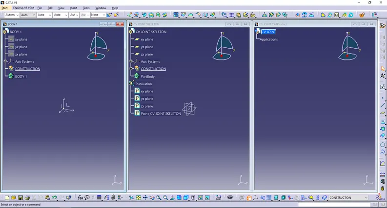
After I have done that,I am going to design first Part – BODY 1 as is given in pdf link.
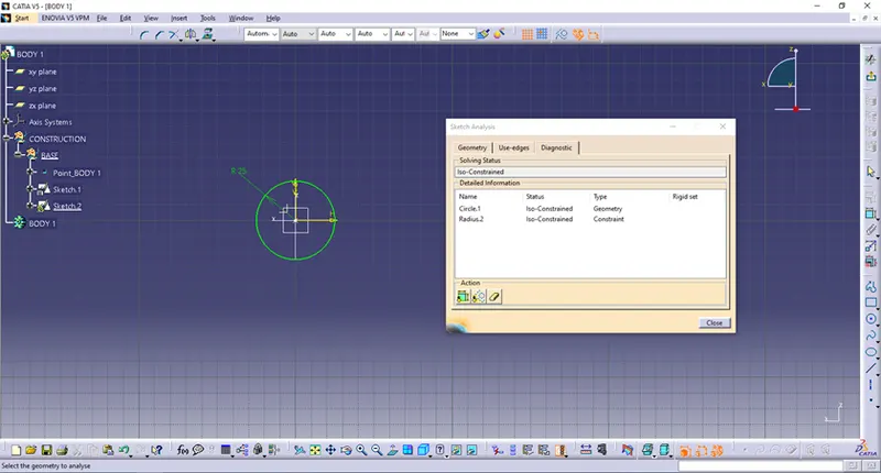
I am making CONSTRUCTION Geometrical Set and under it BASE with base sketch and a point that I will publish.
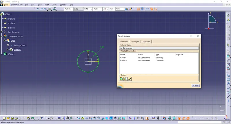
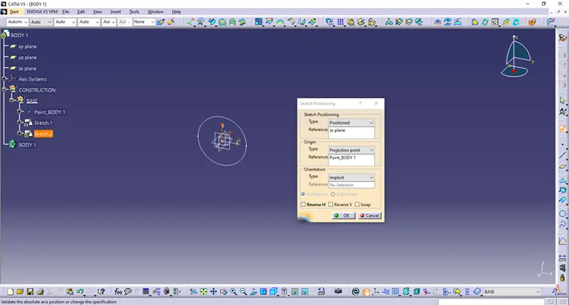
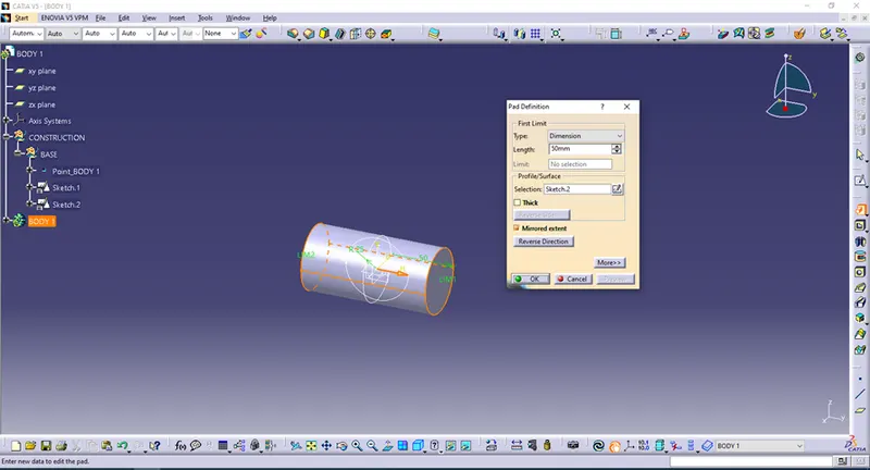
Then I have paded it and add fillets.
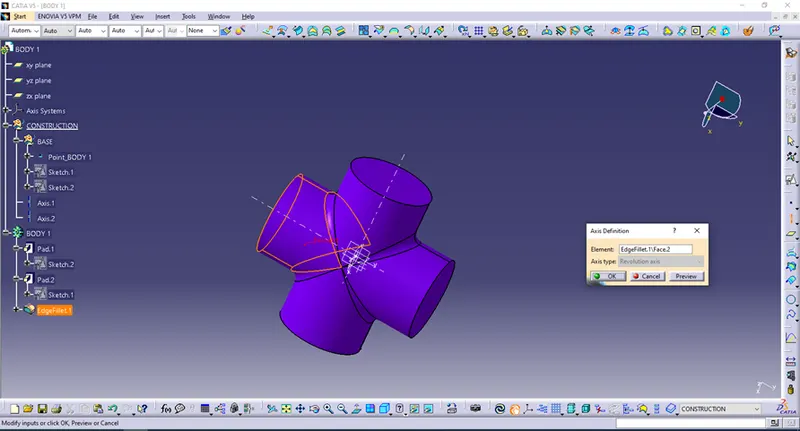
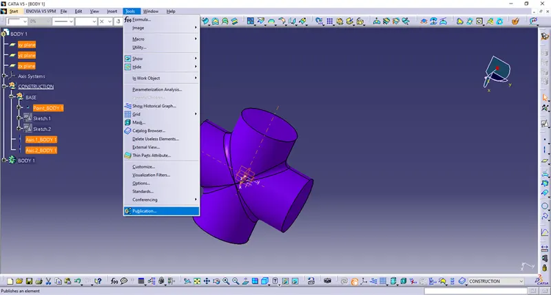
After that I have made axiss and published all necessary elements.
I am going to make BODY 2 now.I am inserting Geometrical Sets CONSTRUCTION and under it BASE,SHELL,SHELL REMOVE and PUBLICATION.I am also inserting new Bodies and renaming them as BASE,SHELL and SHELL REMOVE.
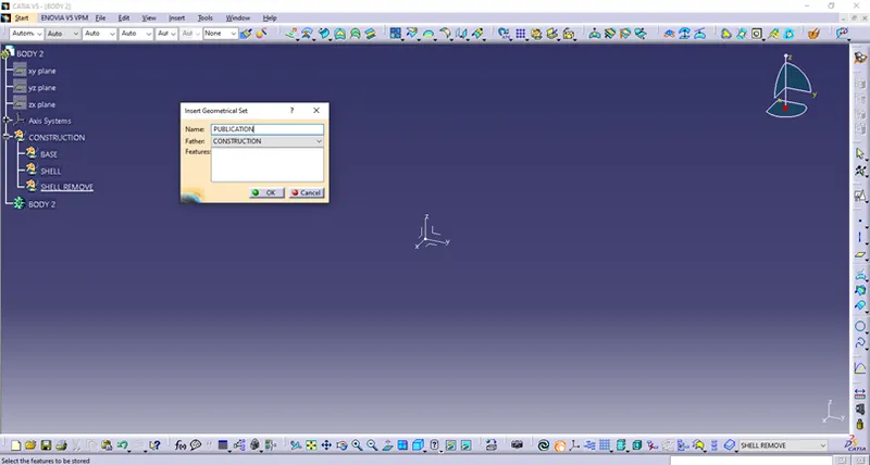
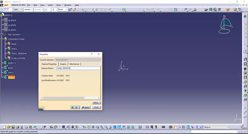
I have done BODY 2 modeling as shown on images.
BASE
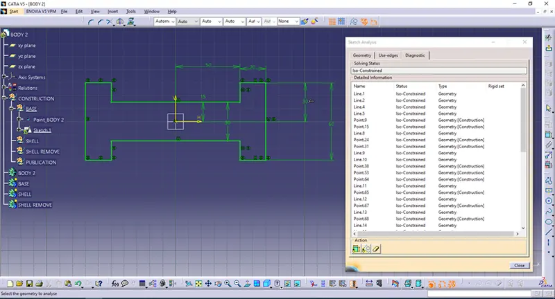
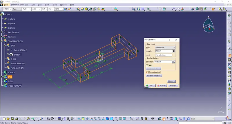
SHELL
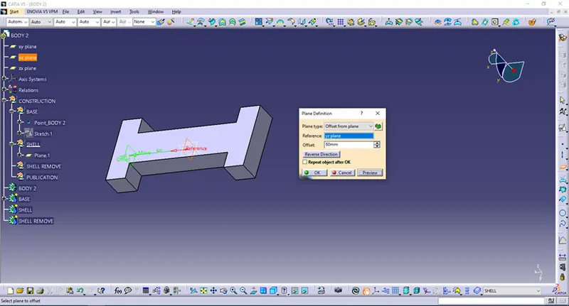
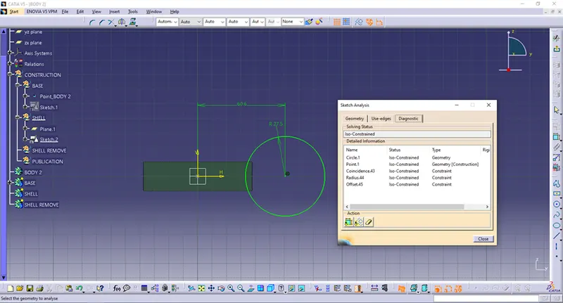
I have copy-pasted SHELL 3X and then added all under BODY 2.
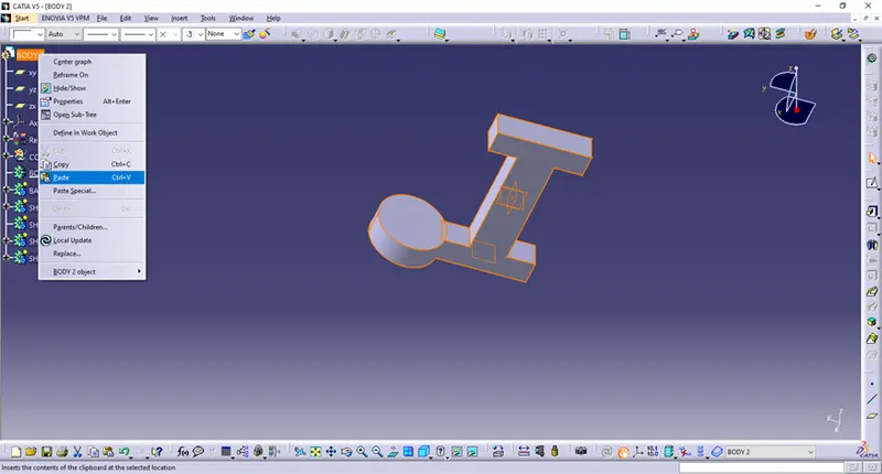
I should reposition all those SHELLs,that is why I have done point in the middle of circle and points in relation to that point.
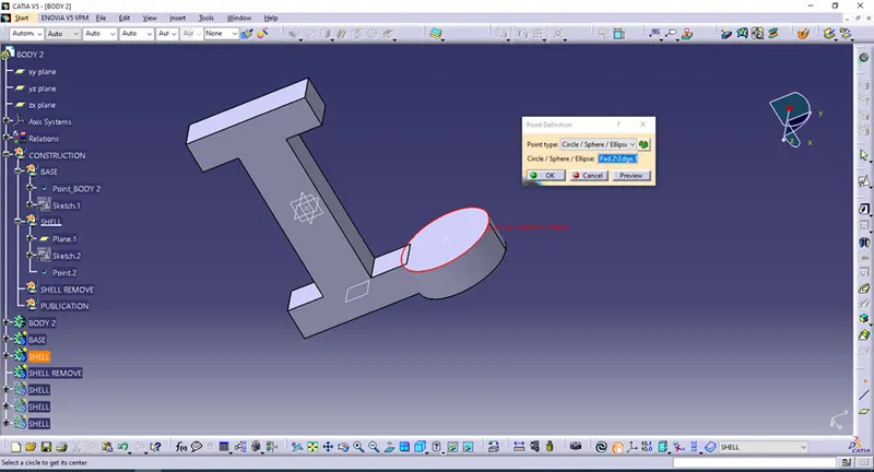
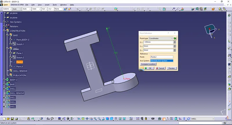
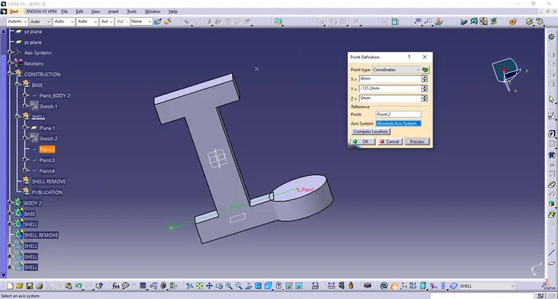
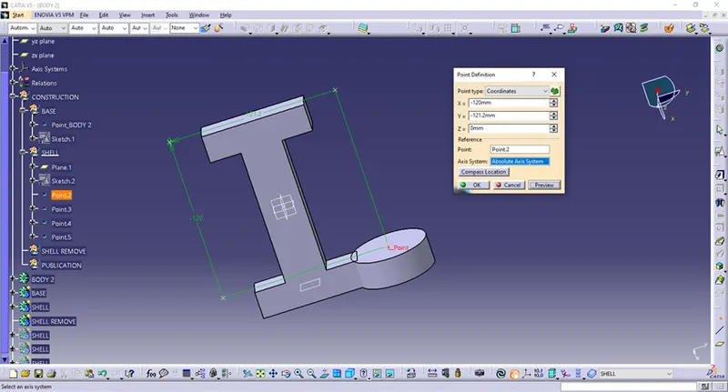
I will move those points in one Geometrical Set – SHELL REPOSITION.
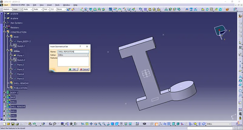
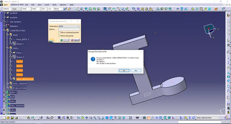
Now comes repositioning.
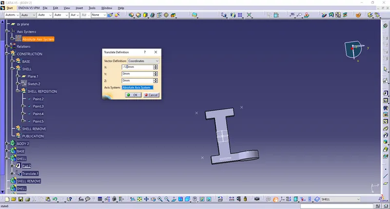
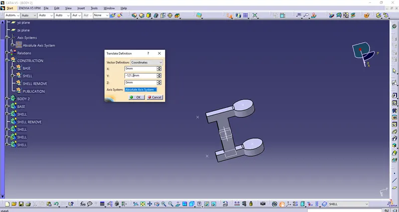
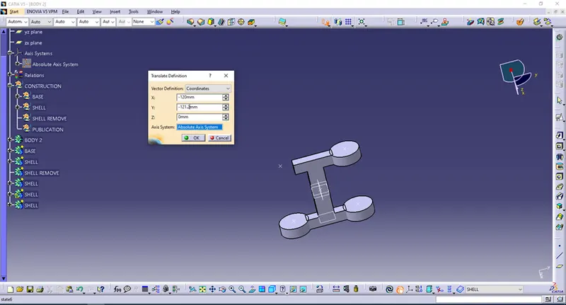
After repositioning I am doing SHELL REMOVE Features.
I will first insert a plane and on it make Positioned Sketch for removing feature.
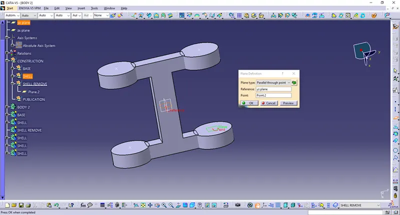
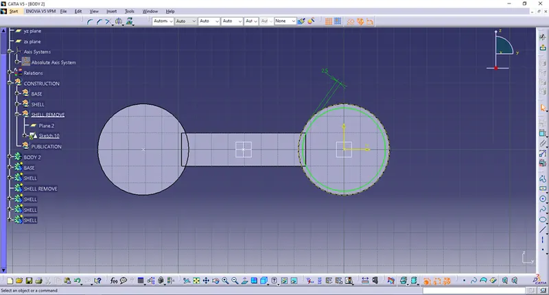
Then I have paded feature as follows and mirrored it.
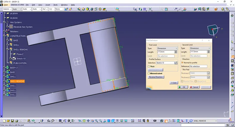
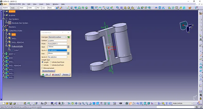
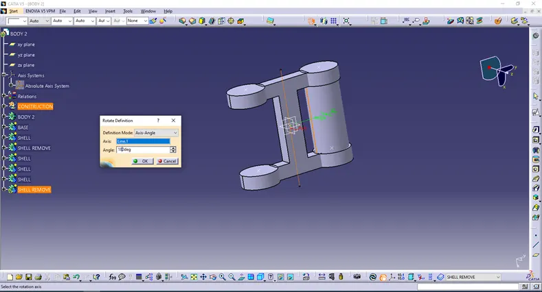
After I have done that,I have reordered the Features and assembled them with add and remove options.
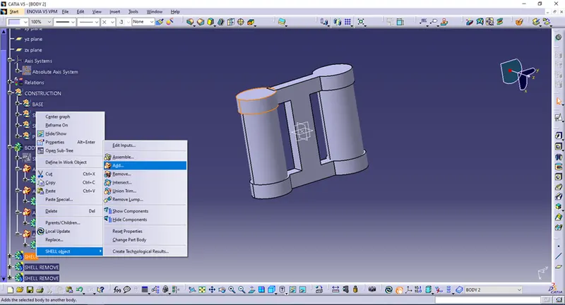
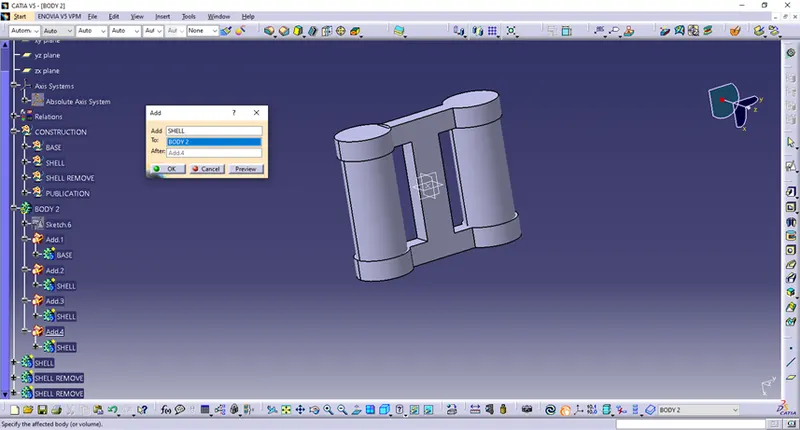
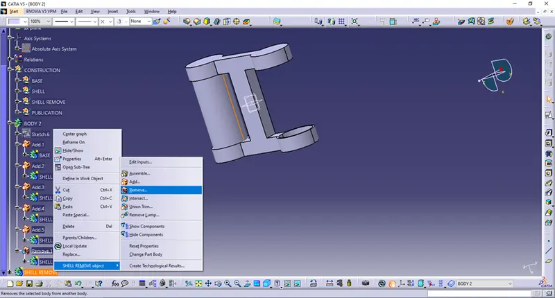
Finally I have filleted BODY 2 feature.
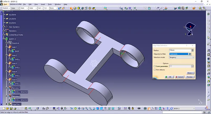
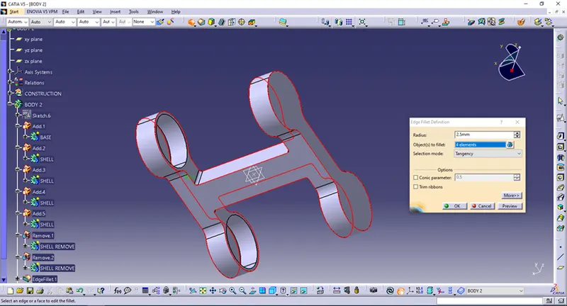
I am going to make BODY 3.I have opened next CatPart and rename it as a BODY 3.Geometrical Set I have renamed as CONSTRUCTION and there I have inserted BASE,SHELL,SHELL REMOVE and PUBLICATION Geometrical Sets.
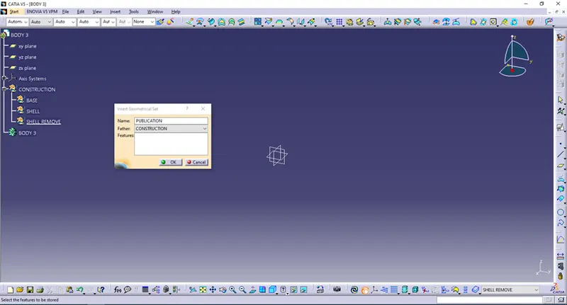
I have made first feature – BASE.
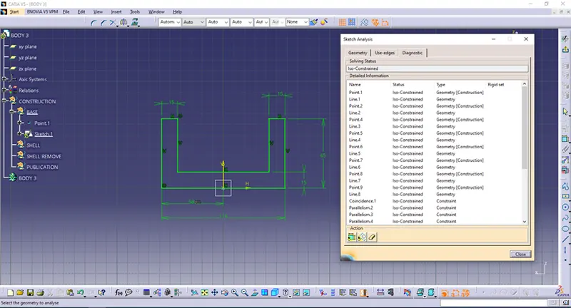
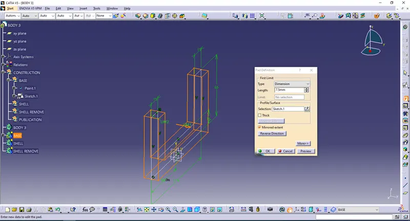
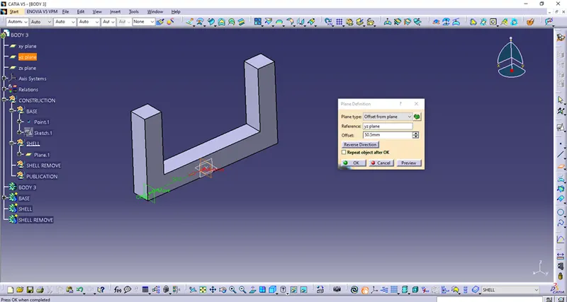
Now comes SHELL.I have made Plane for a Positioned Sketch first.
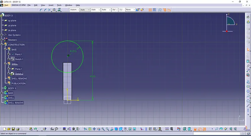
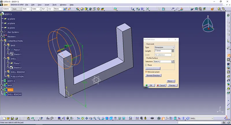
I have copy-pasted SHELL faeture and translated it as it is shown.
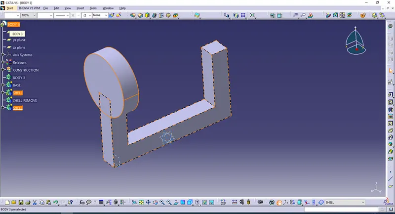
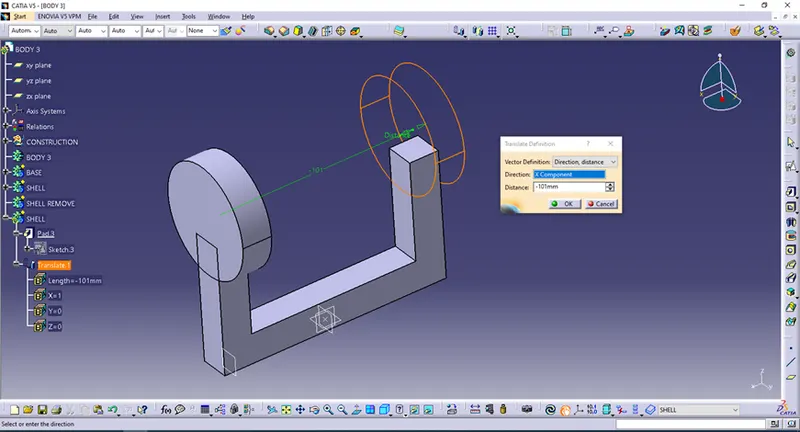
I am making last feature in BODY 3 – SHELL REMOVE.
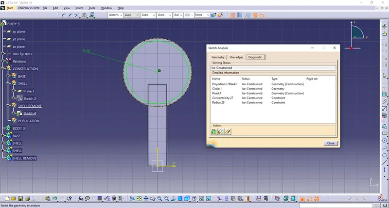
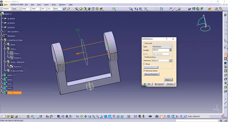
With add – remove options I will bring assembly in proper shape.
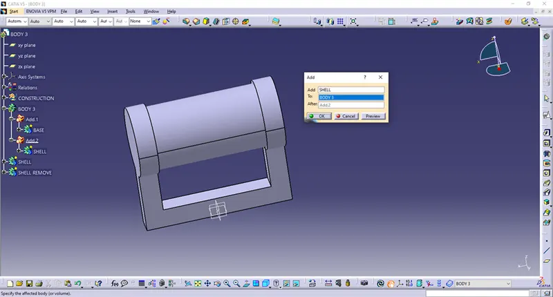
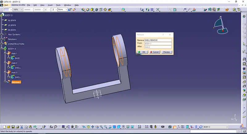
I will add fillets to BODY 3.
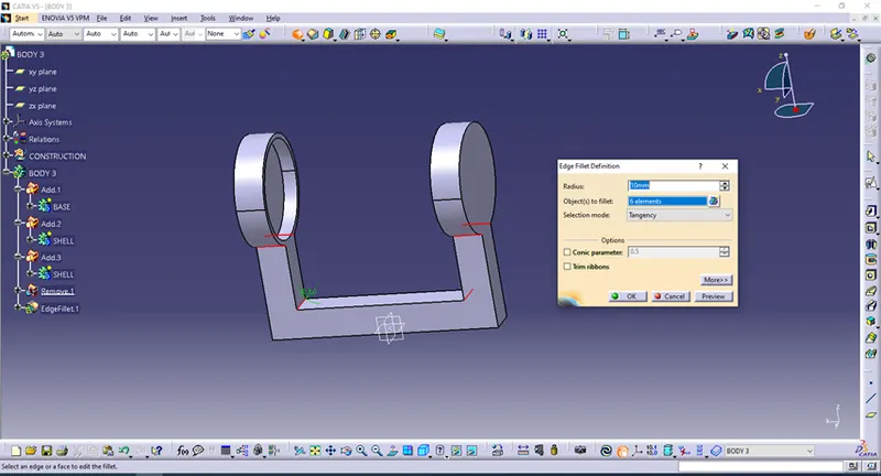
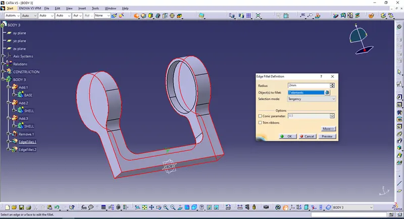
Afterwards I have seen one feature down in the middle is missing – then I have copy-pasted complete Add Feature with Shell and Shell remove and I have changed Add to Uniontrim.
As it can be seen,I have to rotate and translate SHELL and SHELL REMOVE copied origin features to bring it on right position.I have to also adjust Pad in SHELL REMOVE feature to have proper form.
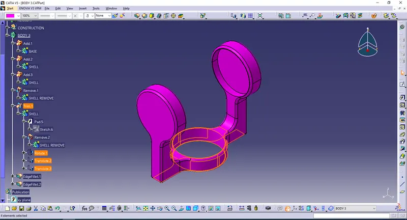
Changing Add to Uniontrim is resulting as shown in image.I have to rearranged fillets also, according to made changes.
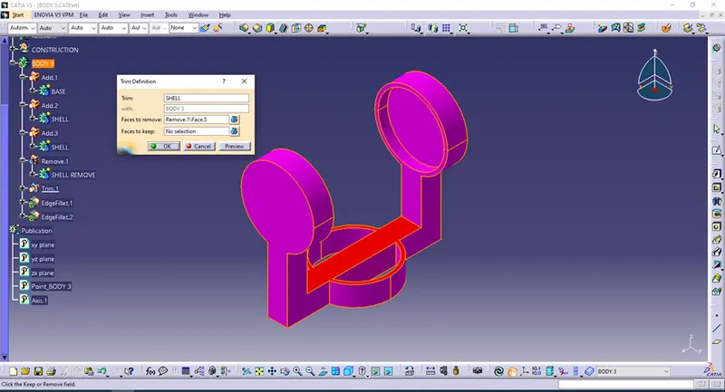
I will add all those parts to CV JOINT assembly.
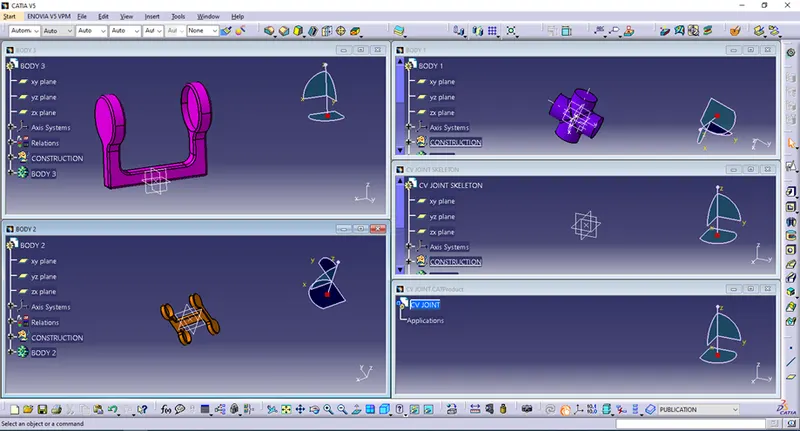
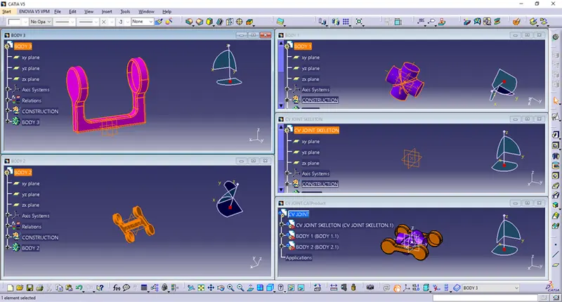
Then,with a Save management I have saved all files in CV JOINT directory.
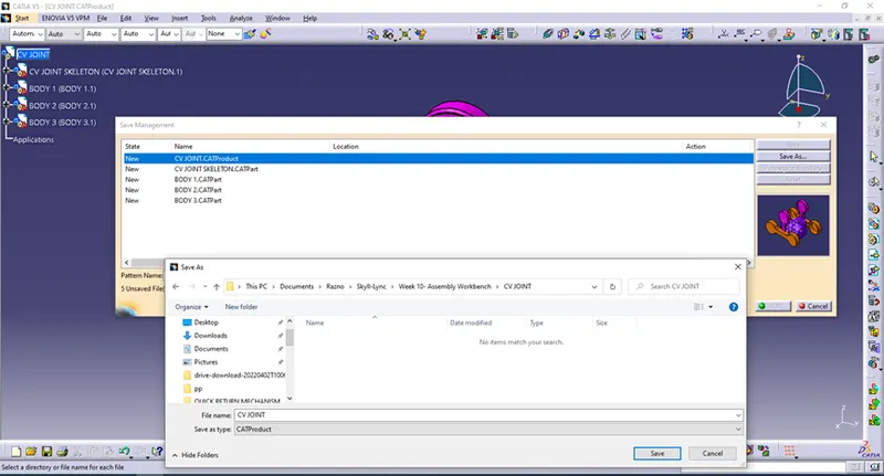
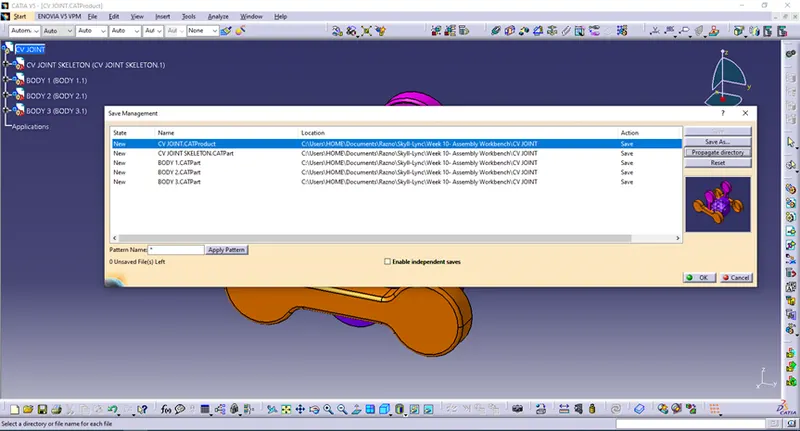
I have to add constraines to parts,but I will first detach parts to have a overview of the assembly.
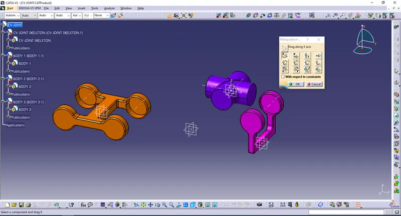
I will first constrained CV JOINT SKELETON – I am going to fix it.
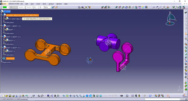
I have also copy-pasted BODY 1 and BODY 3 and then reordered Graph Tree.
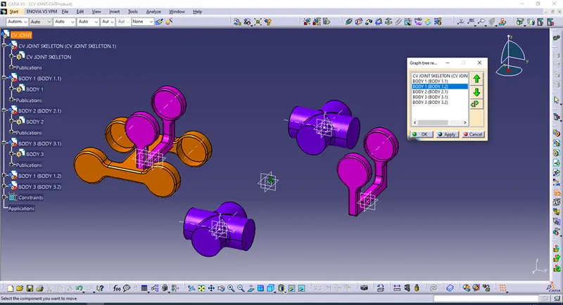
Then,I have added constraines to BODY 2.
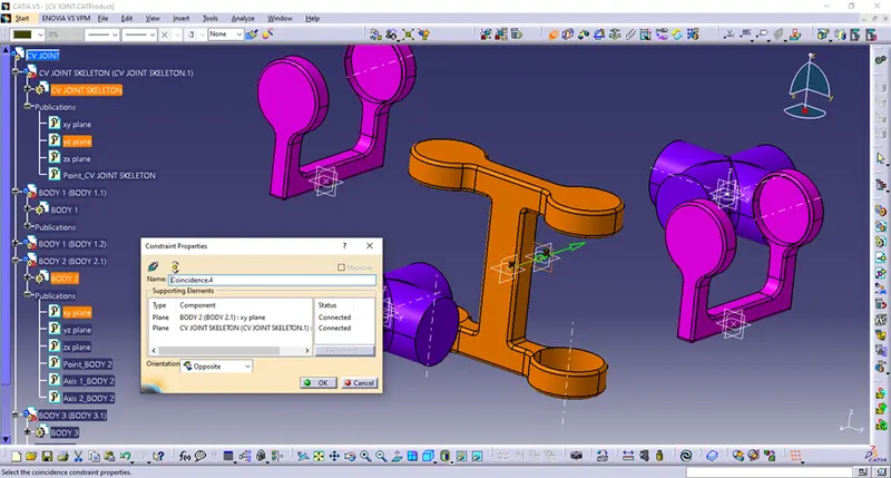
I have constrained BODY 1 and BODY 2 also – 2 times.
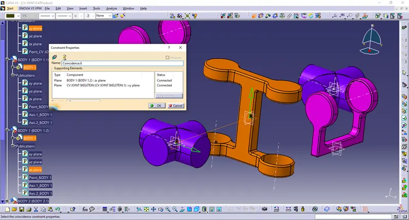
Finally,I have added constraines to BODY 1 and BODY 3 – 2 times.
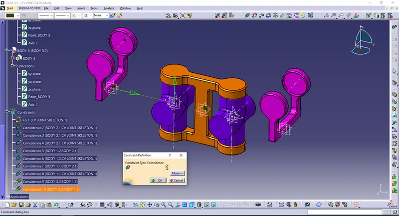
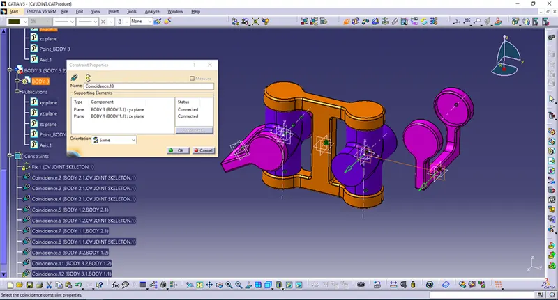
There is CV JOINT assembly,fully constrained (BODY 3 is changed accordingly to changes made).
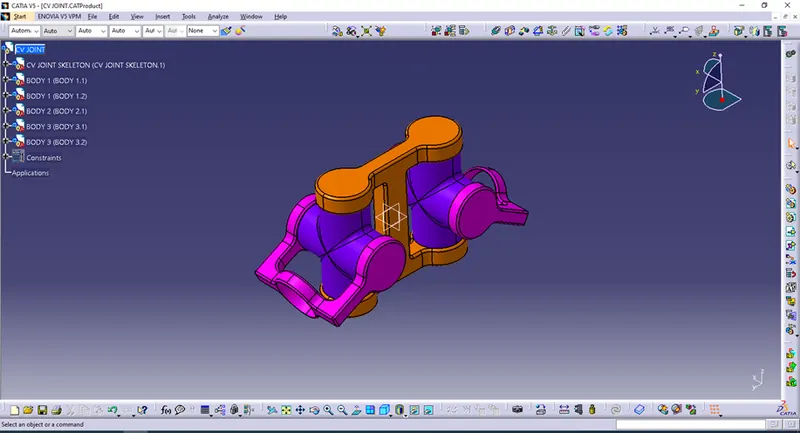
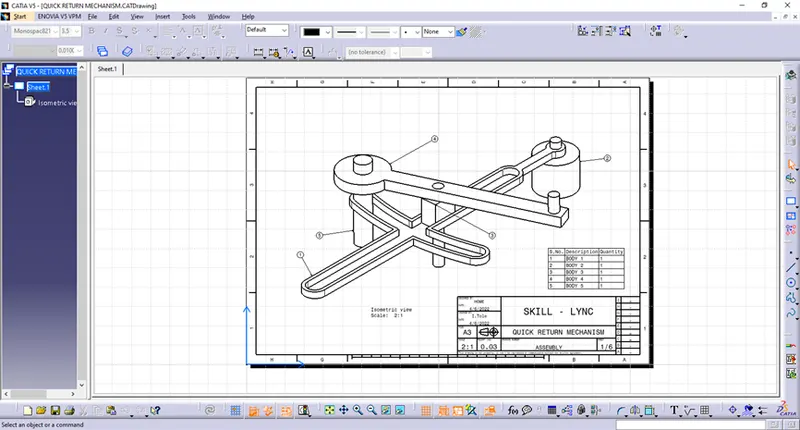
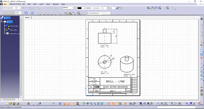
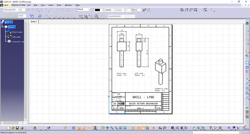
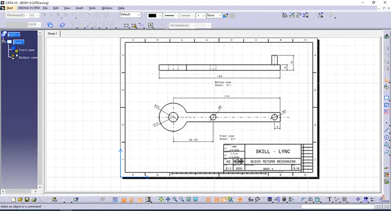
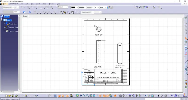
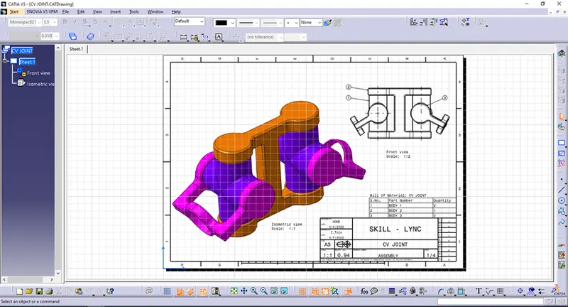
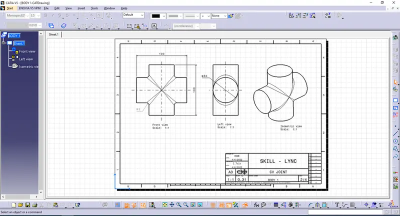
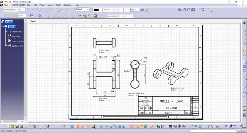
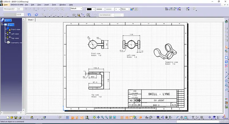
I have done also drawings as required in .pdf files.Drawings are given bellow.
QUICK RETURN MECHANISM
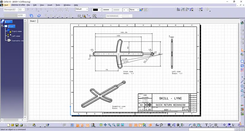
CV JOINT
That is all fellows,challenge is completed.
Best regards,
Ivan Tole