Week 10- Assembly Workbench
Week 10- Assembly Workbench
AIM:- To create a 3 D Solid CAT Part files using 2 D Sketch, also to solve the sketches with fully (ISO) constrained and also to create a 2 D Drafting sheet from the solid CAT part and Assembly Product with the Frame and Tittle Block.
OBJECTIVE:-
- To draw the 2-D sketch in CATIA by using the Positioned sketch in Sketcher Workbench.
- To create a Solid CAT Part using Part Workbench with Sketch based feature and Dress up features.
- To create a complete Assembly for Quick Return Mechanism using Assembly Workbench.
- To create a complete Assembly for CV Joint using Assembly Workbench.
- To create a 2D Draft sheet using Drafting workbench.
- To follow the Design standards and to Align the views in a proper way.
- To Import the Frame/Border and Tittle Block in the 2D draft sheet to locate the drawing inside the sheet to guide.
- To Dimensionate the 2D using the feature in the Drafting workbench.
ASSEMBLY :-
Assembly modeling is a technology and method used by computer-aided design and product visualization computer software systems to handle multiple files that represent components within a product. The components within an assembly are represented as solid or surface models.
DRAWING:-01
QUICK RETURN MECHANISM:-
A quick return mechanism is an apparatus to produce a reciprocating motion in which the time taken for travel in return stroke is less
than in the forward stroke.
It is driven by a circular motion source (typically a motor of some sort) and uses a system of links with three turning pairs and a sliding pair.
There are three types of Quick return mechanism.
Procedure :-
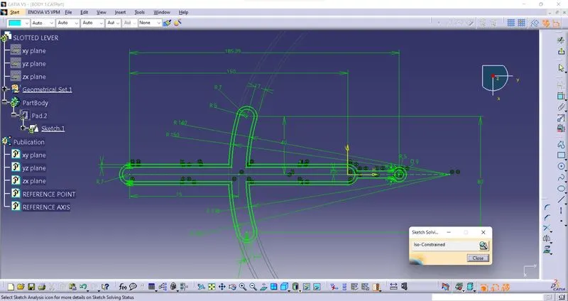
1) Create a all sketch by using positioned sketch command.
2) Ensure that all the sketches in iso- constrained.
BODY:-01
SKETCH:-
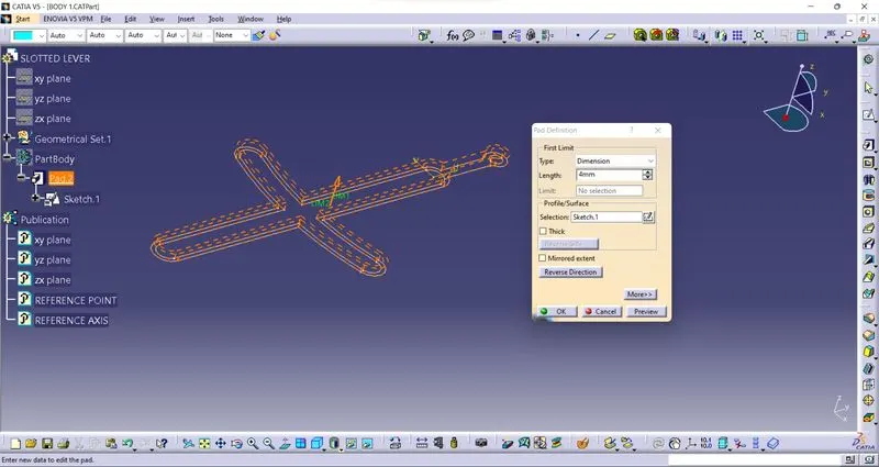
PAD:-
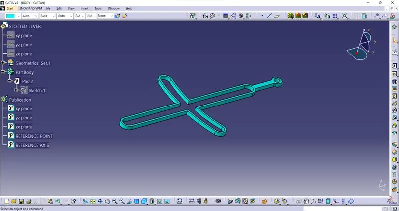
FINAL BODY:-
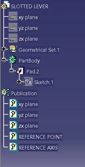
GEOMETRICAL TREE STRUCTURE:-
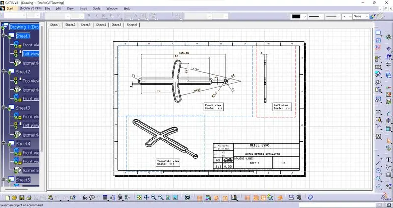
DRAFTING:-
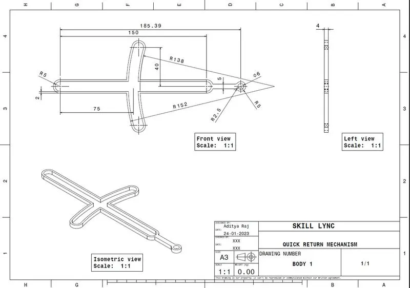
PDF SCREEN SHOT:-
BODY:-02
SKETCH:-
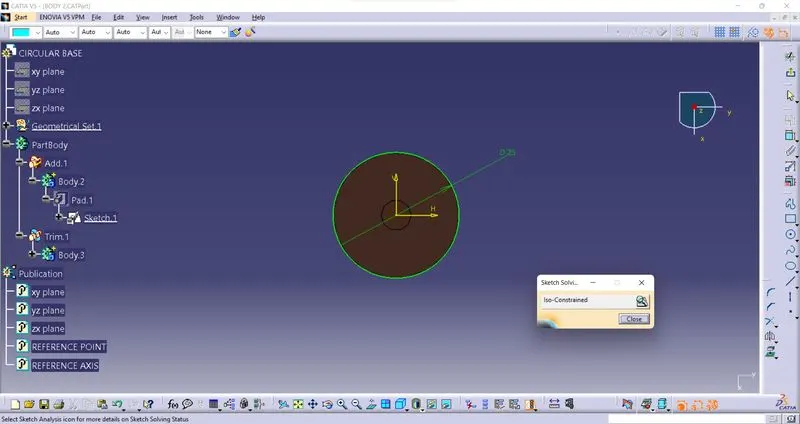
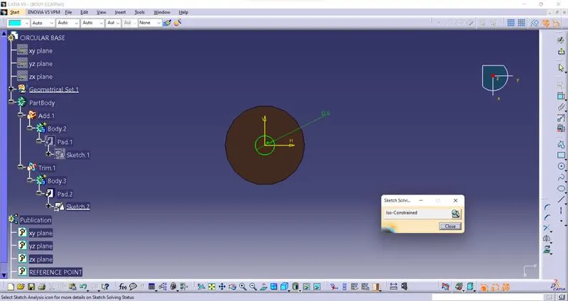
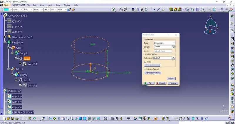
PAD:-
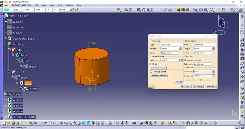
AFTER TRIMING WE GET(WE COULD HAVE USED MULTIPAD ALSO FOR THIS BODY)
FINAL BODY:-
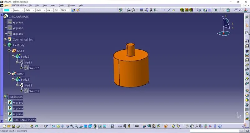
GEOMETRICAL TREE STRUCTURE:-
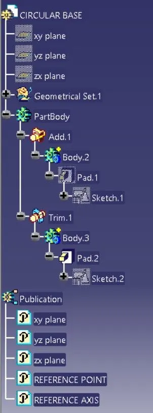
DRAFTING:-
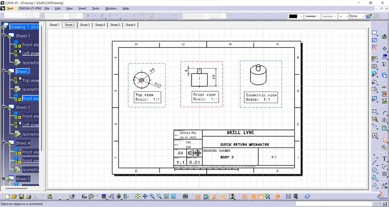
PDF SCREEN SHOT:-
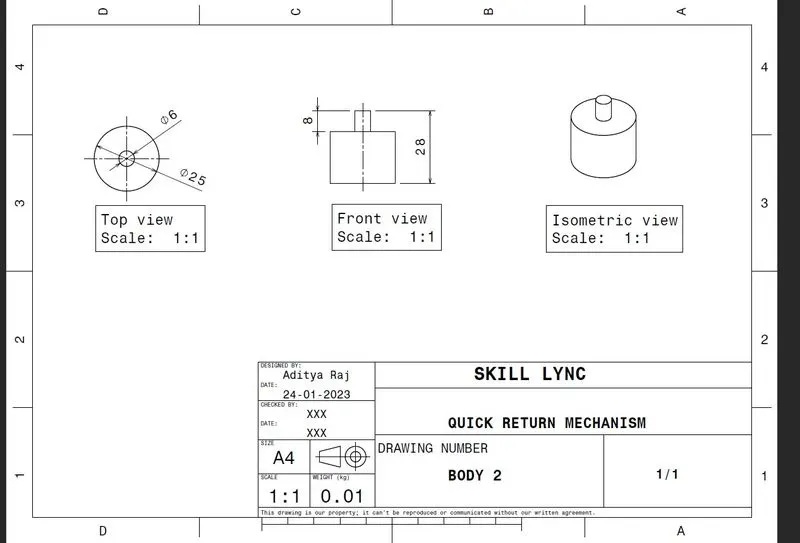
BODY:-03
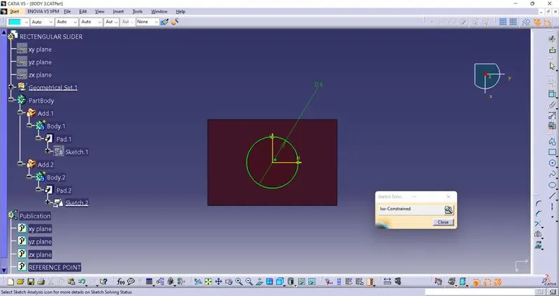
SKETCH:-
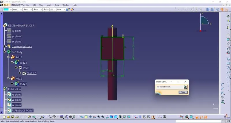
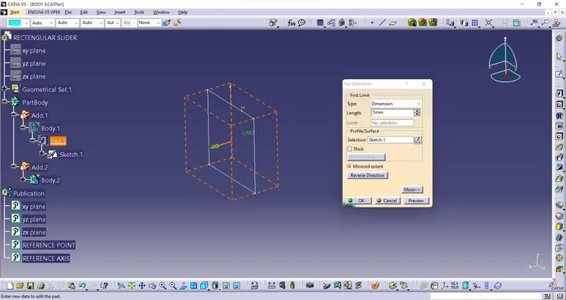
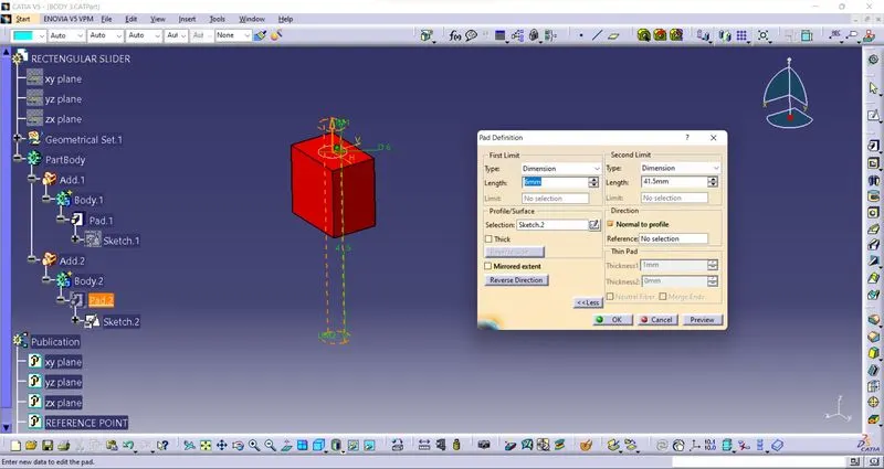
PAD:-
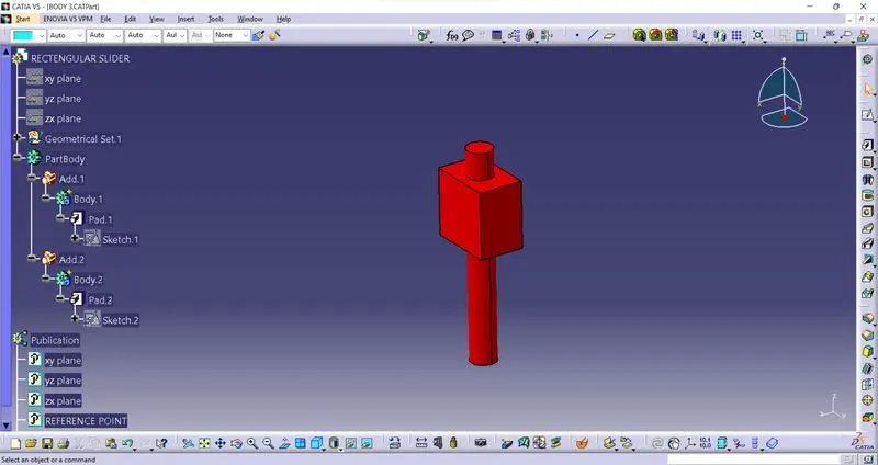
AFTER ADD BOTH BODY WE GET
FINAL BODY:-
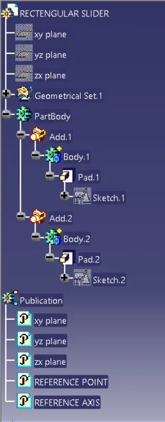
GEOMETRICAL TREE STRUCTURE:-
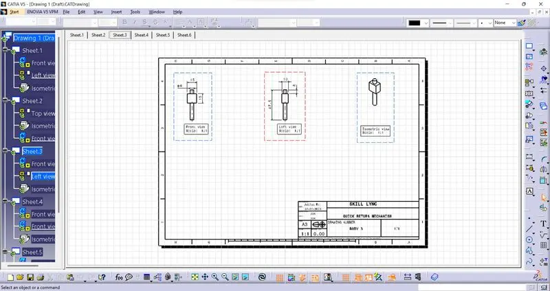
DRAFTING:-
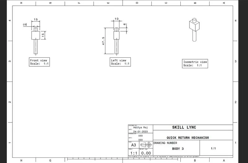
PDF SCREEN SHOT:-
BODY:-04
SKETCH:-
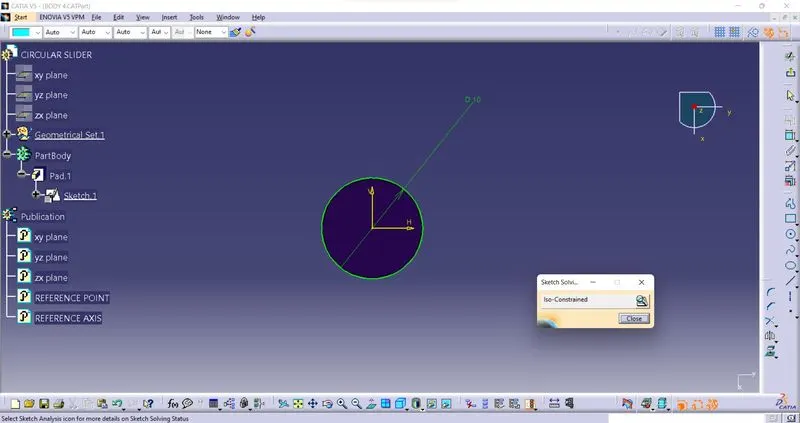
PAD:-
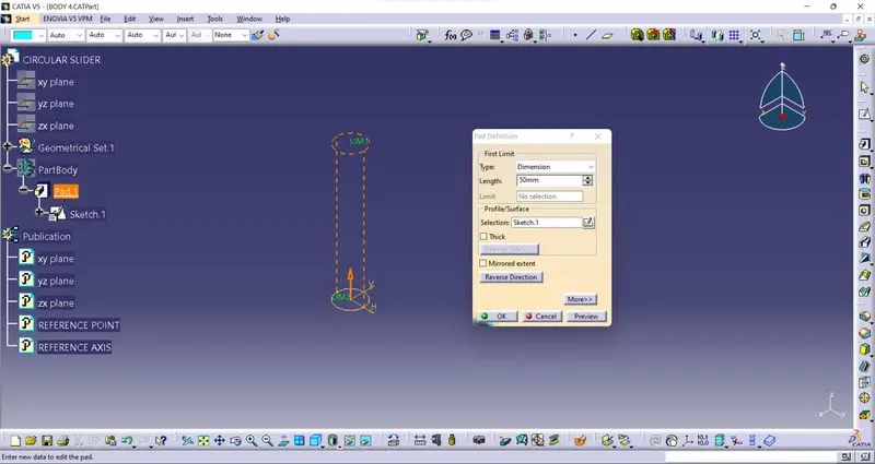
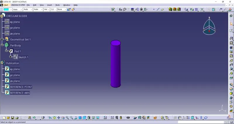
FINAL BODY:-
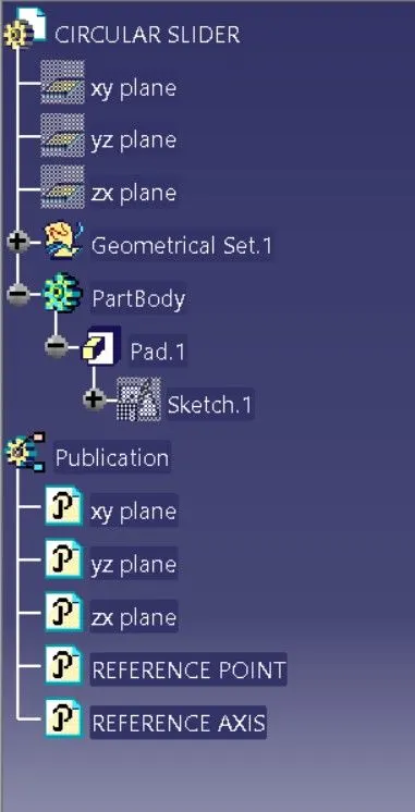
GEOMETRICAL TREE STRUCTURE:-
DRAFTING:-
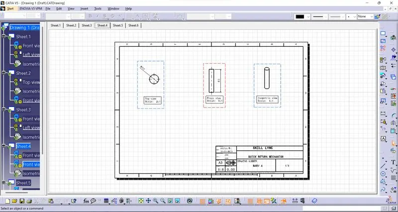
PDF SCREEN SHOT:-
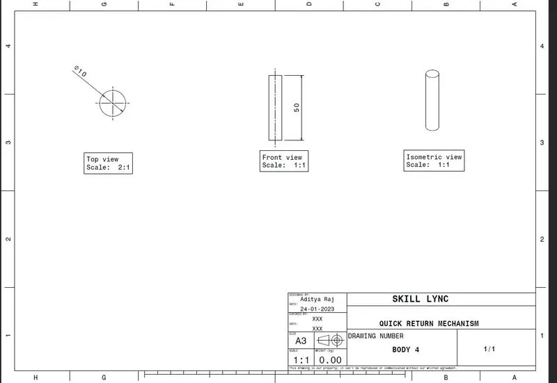
BODY:-05
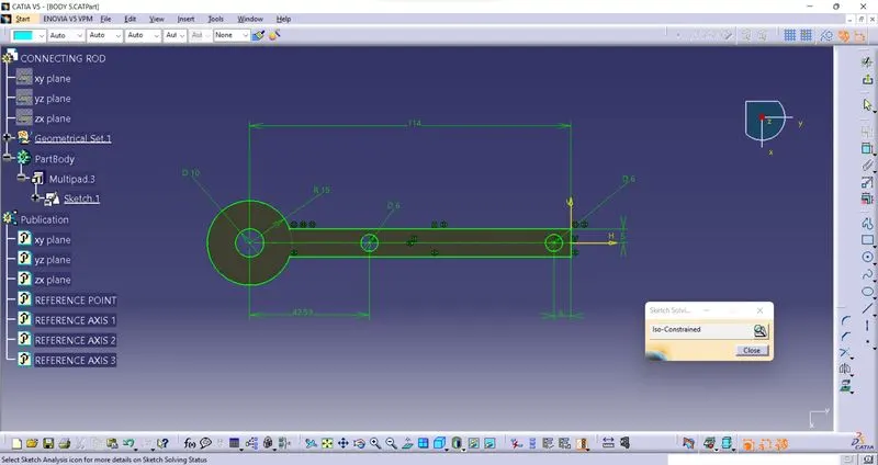
SKETCH:-
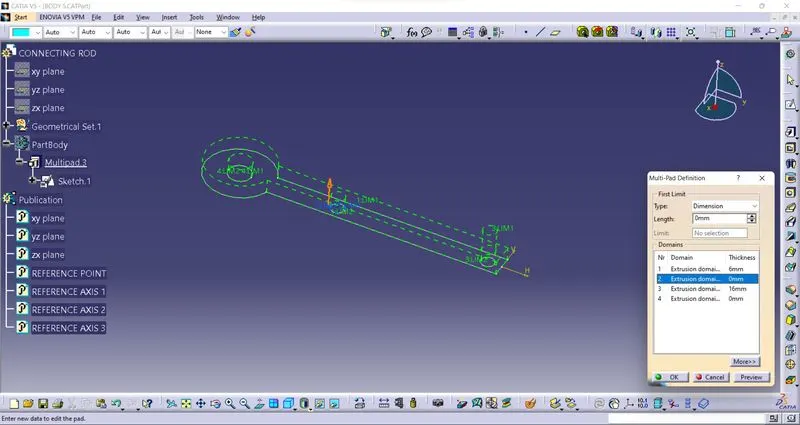
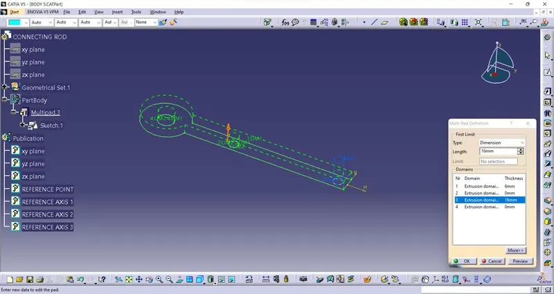
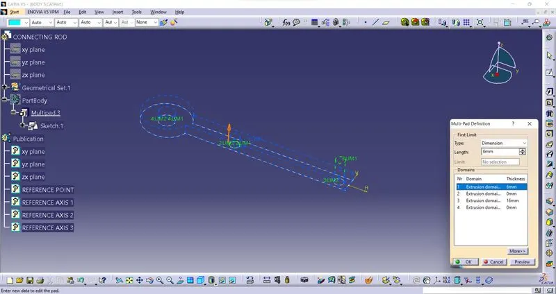
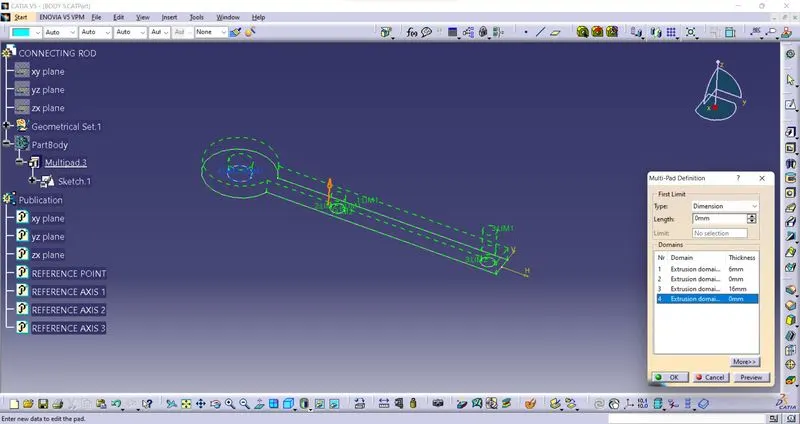
MULTIPAD:-
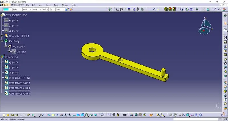
FINAL BODY:-
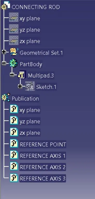
GEOMETRICAL TREE STRUCTURE:-
DRAFTING:-
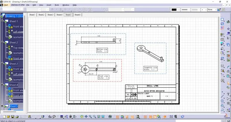
PDF SCREEN SHOT:-
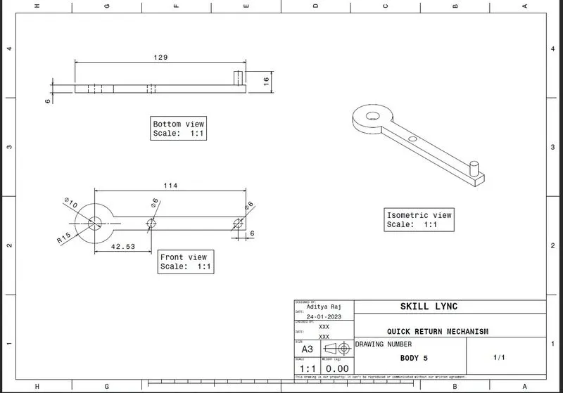
ASSEMBLY:-
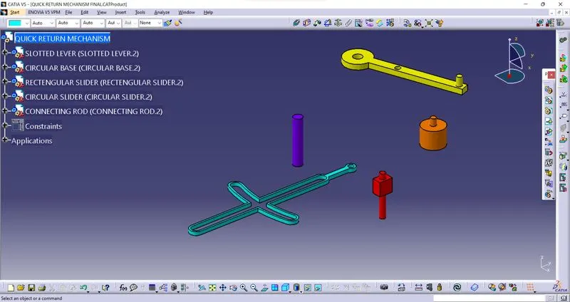
IMPORTED PARTS BODY:-
FIRST IMPORT ALL PART BODY IN THE PRODUCT DESIGN THEN ASSEMBLE THEM.
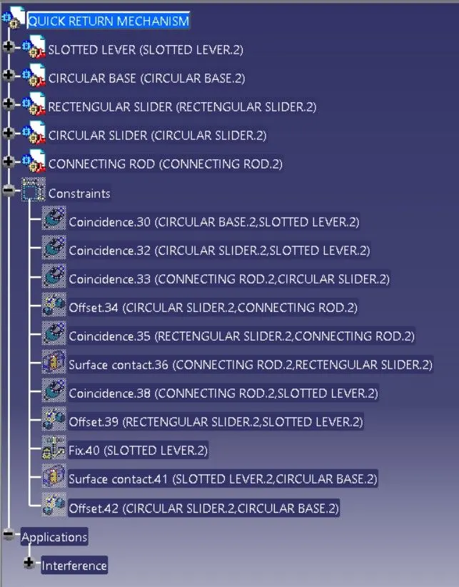
By using the Fix Constraint the reference points are been fixed by which all the DOF are been arrested, preventing this component from moving from its parents during the update operation. The component is fixed by selecting one of its geometrical element at least. Coincidence constraints are used to align elements. Depending on the selected elements, you may obtain concentricity, coaxiality or coplanarity. By which the Axis are been selecetd andconstrained accordingly.
ASSEMBLED BODY:-
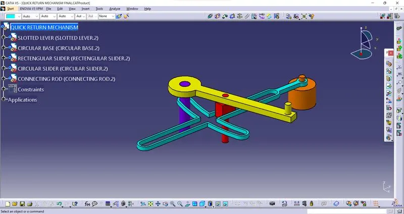
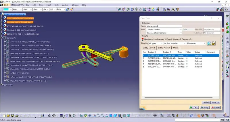
CHECK:-
For checking use clash tool if all body are connected then your assembling will be right if clash then change the constrain of the part body then assemble again.
GEOMETRICAL TREE STRUCTURE:-
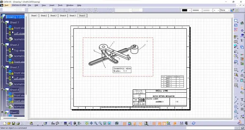
DRAFTING:-
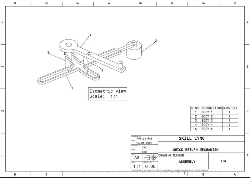
PDG SCREEN SHOT:-
DRAWING:-02
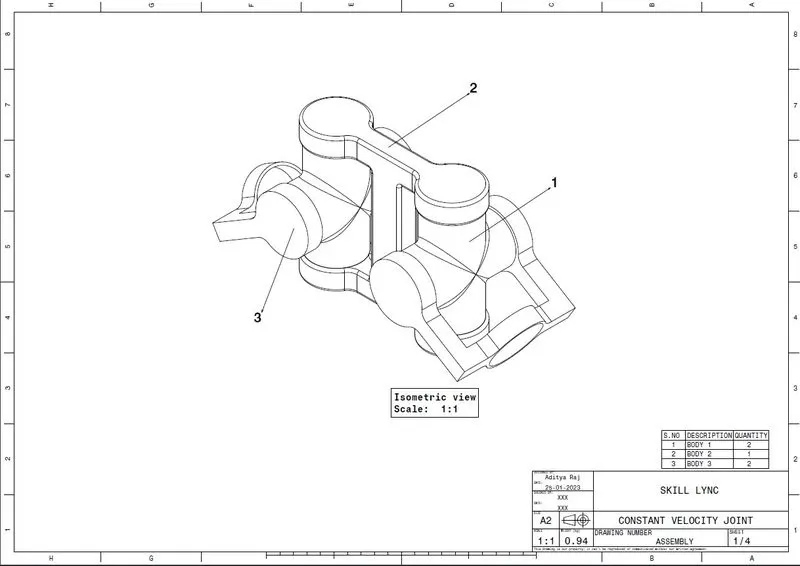
CV JOINT :-
Constant-velocity joints (also known as homokinetic or CV joints) allow a drive shaft to transmit power through a variable angle, at
constant rotational speed, without an appreciable increase in friction or play.
They are mainly used in front wheel drive vehicles. Modern rear wheel drive cars with independent rear suspension typically use CV joints at the ends of the rear axle halfshafts and
increasingly use them on the drive shaft.
Procedure :-
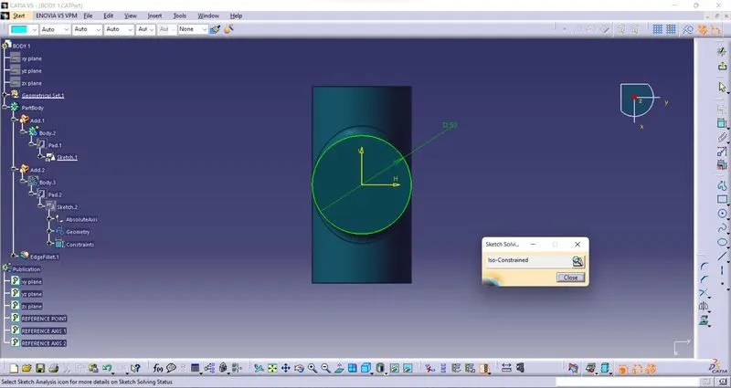
1) Create a all sketch by using positioned sketch command.
2) Ensure that all the sketches in iso- constrained.
BODY:-01
SKETCH:-
PAD:-
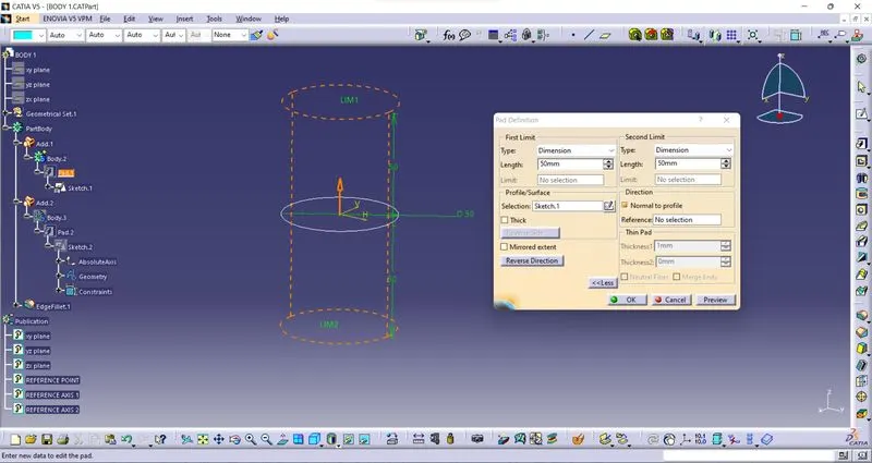
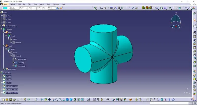
Take a same dimension sketch for horizontal axis pad it and add the both body together to get the final body.
FINAL BODY:-
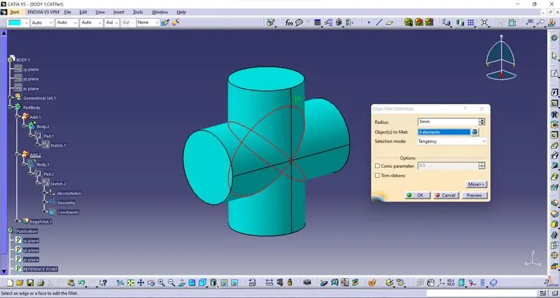
EDGE FILLET:-
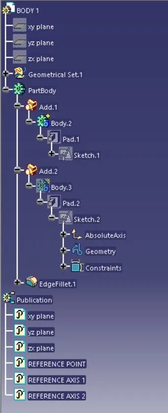
GEOMETRICAL TREE STRUCTURE:-
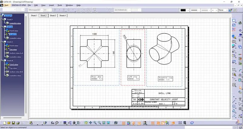
DRAFTING:-
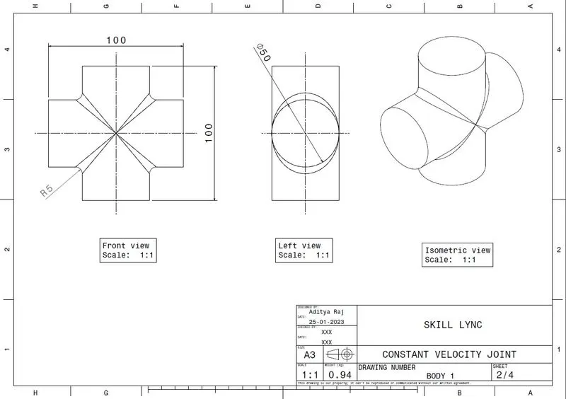
PDF SCREEN SHOT:-
BODY:-02
SKETCH:-
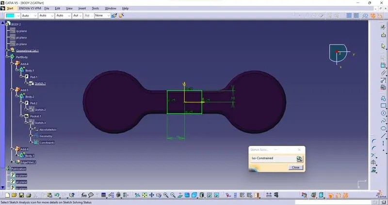
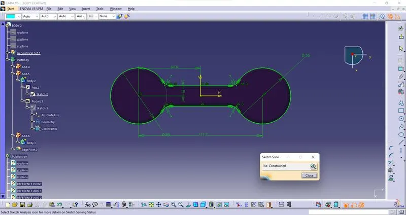
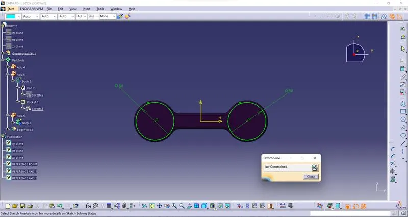
PAD:-
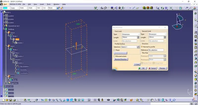
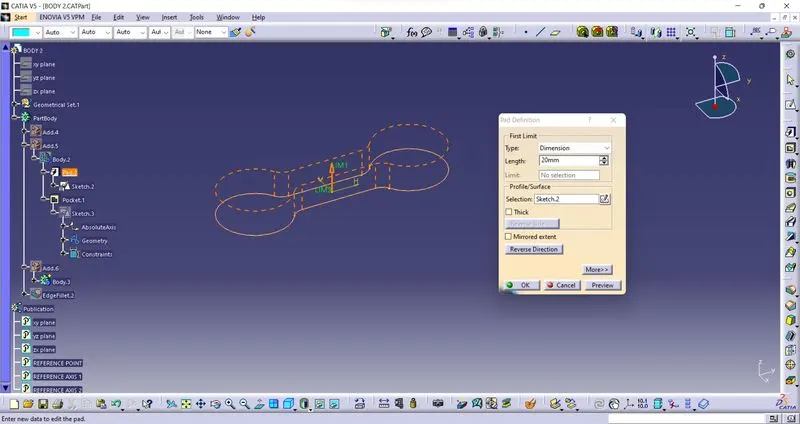
POCKET:-
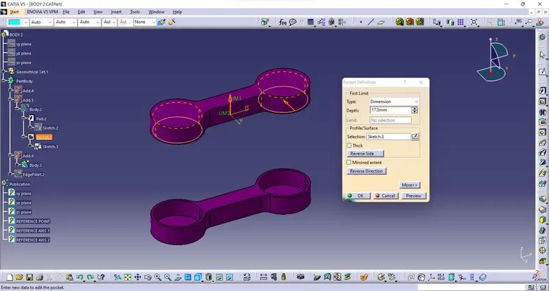
APPLY BOOLEAN OPERATION:-
FINAL BODY:-
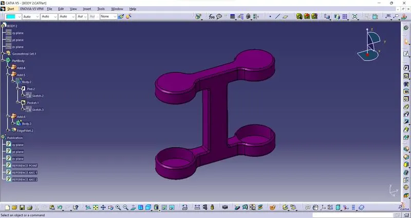
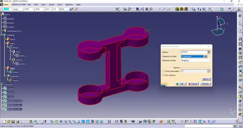
EDGE FILLET:-
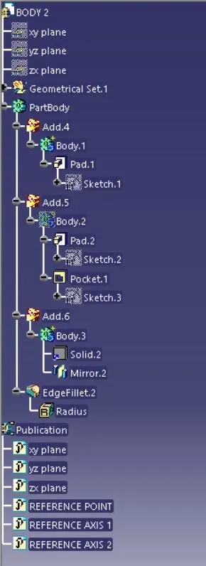
GEOMETRICAL TREE STRUCTURE:-
DRAFTING:-
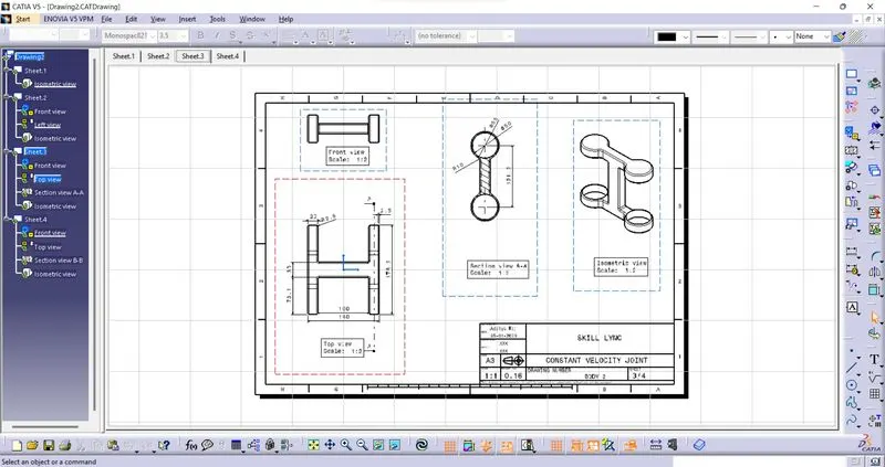
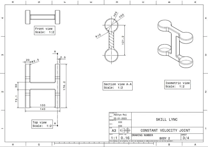
PDF SCREEN SHOT:-
BODY:-03
SKETCH:-
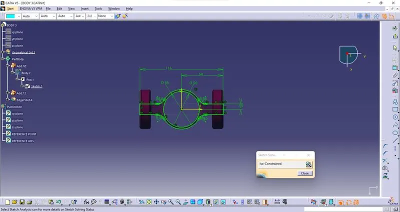
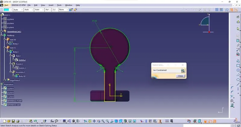
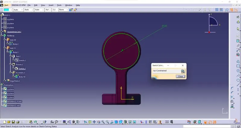
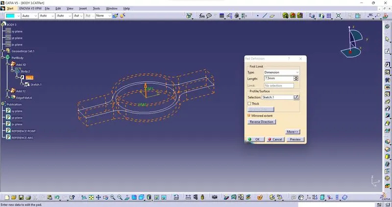
PAD:-

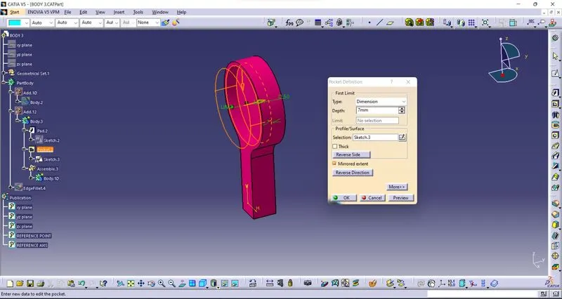
POCKET:-
Translate the side body and apply boolean operation we get.
FINAL BODY:-
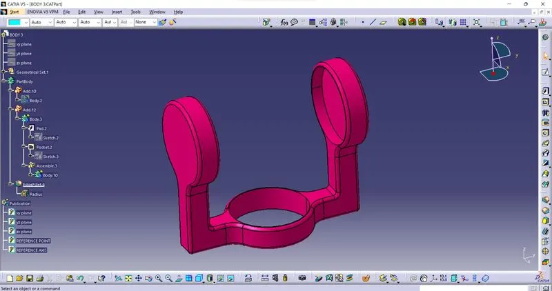
EDGE FILLET:-
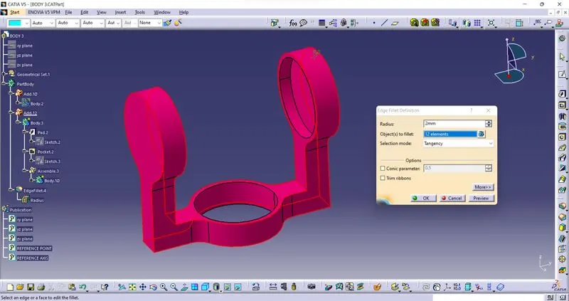
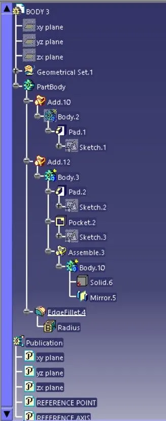
GEOMETRICAL TREE STRUCTURE:-
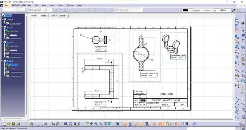
DRAFTING:-
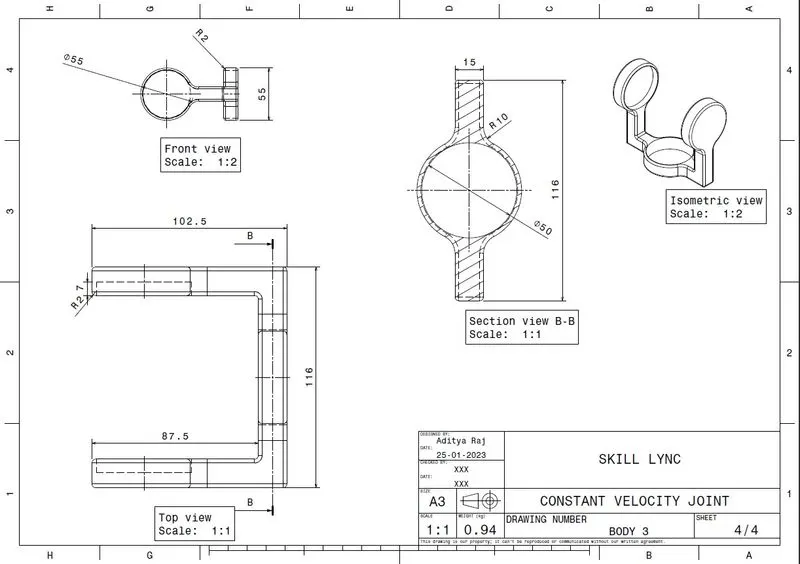
PDF SCREEN SHOT:-
ASSEMBLY:-
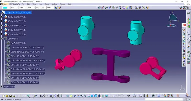
IMPORTED PARTS BODY:-
FIRST IMPORT ALL PART BODY IN THE PRODUCT DESIGN THEN ASSEMBLE THEM.
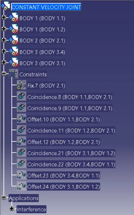
By using the Fix Constraint the reference points are been fixed by which all the DOF are been arrested, preventing this component from moving from its parents during the update operation. The component is fixed by selecting one of its geometrical element at least. Coincidence constraints are used to align elements. Depending on the selected elements, you may obtain concentricity, coaxiality or coplanarity. By which the Axis are been selecetd andconstrained accordingly.
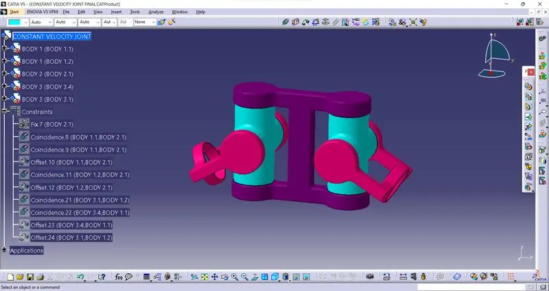
ASSEMBLED BODY:-
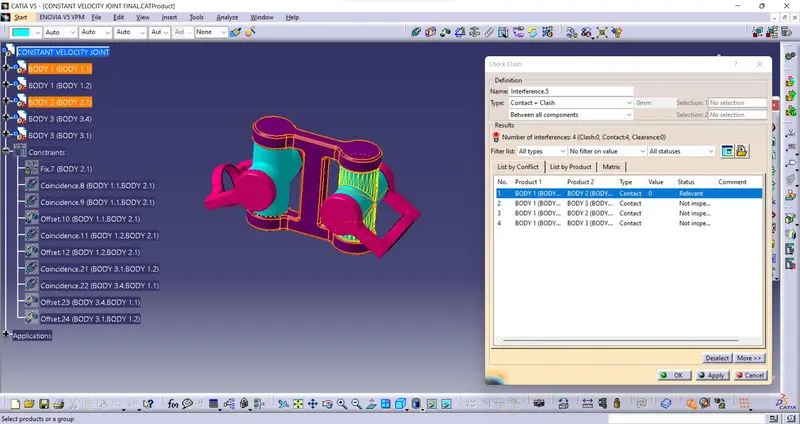
CHECK:-
For checking use clash tool if all body are connected then your assembling will be right if clash then change the constrain of the part body then assemble again.
GEOMETRICAL TREE STRUCTURE:-
DRAFTING:-
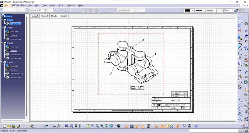
PDF SCREEN SHOT:-