Week 10- Assembly Workbench
AIM :
To create part models and assemble the components using the 2D drawings which were provided.
OBJECTIVE :
To Create a individual part from given 2D drawing.
To Create a assembly from individual part by using assembly workbench
To create a 2D drawing of those part by using Drafting.
ASSEMBLY :-
Assembly modeling is a technology and method used by computer-aided design and product visualization computer software systems to handle multiple files that represent components within a product. The components within an assembly are represented as solid or surface models.
QUICK RETURN MECHANISM:
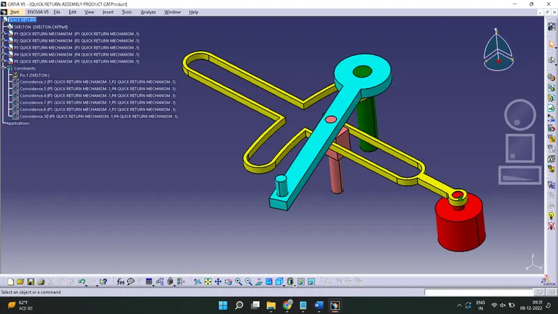
A quick return mechanism is an apparatus to produce a reciprocating motion in which the time taken for travel in return stroke is less than in the forward stroke. It is driven by a circular motion source (typically a motor of some sort) and uses a system of link with three turning pairs and a sliding pair. A quick return mechanism is a subclass of a slider crank linkage, with an offset crank.
Quick return is a common feature of tools in which the action is performed in only one direction of the stroke, such as shapers and powered saws because it allows less time to be spent on returning tool to its initial position.
First of all need to create a 2D to create a 2D drawing of all part then use a PART workbench to convert it in a solid by using Boolean operation and use a drafting workbench for create a 2D drawing of it.
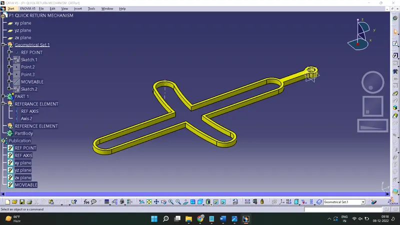
Part 1:-
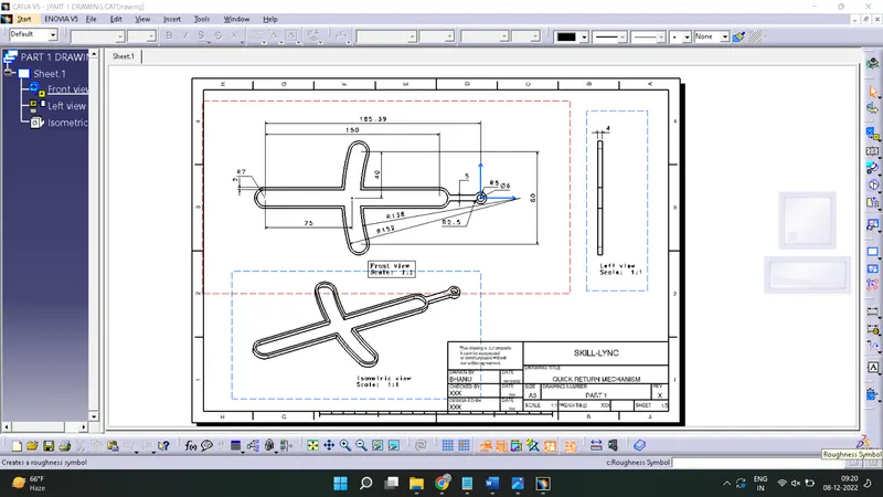
2D Drawing of Part1:-
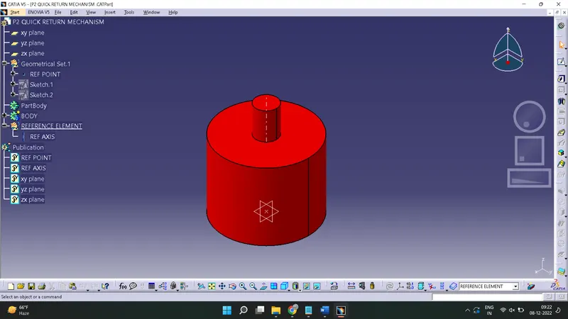
Part 2:-
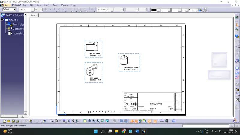
2D Drawing of Part 2:-
Part 3-
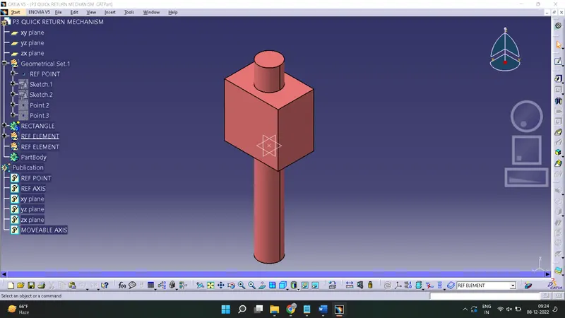
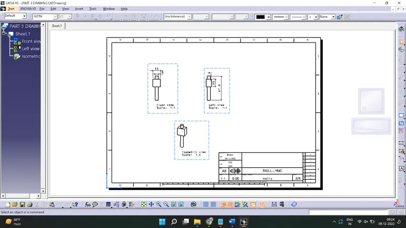
2D Drawing of Part 3:-
Part 4:-
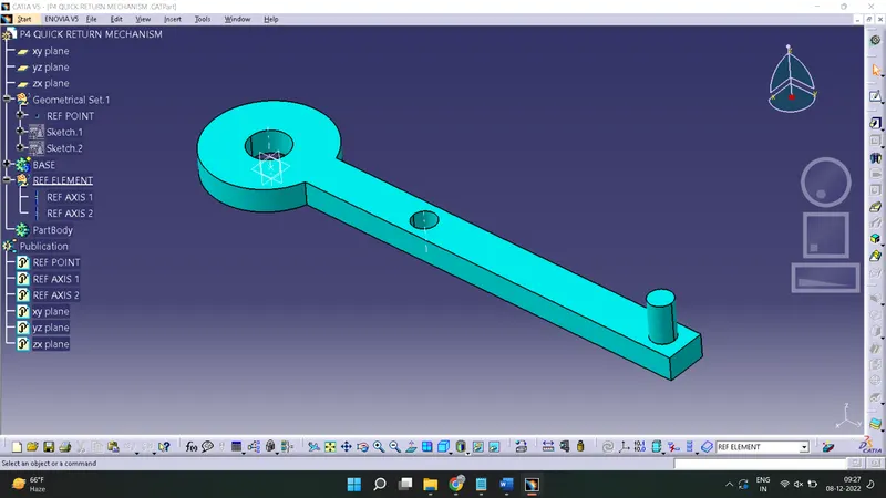
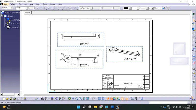
2D Drawing of Part 4:-
Part 5:-
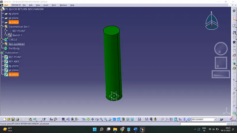
2D Drawing of Part5:-
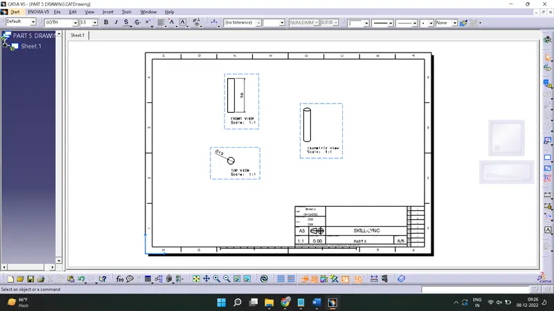
Assembly of all parts:-
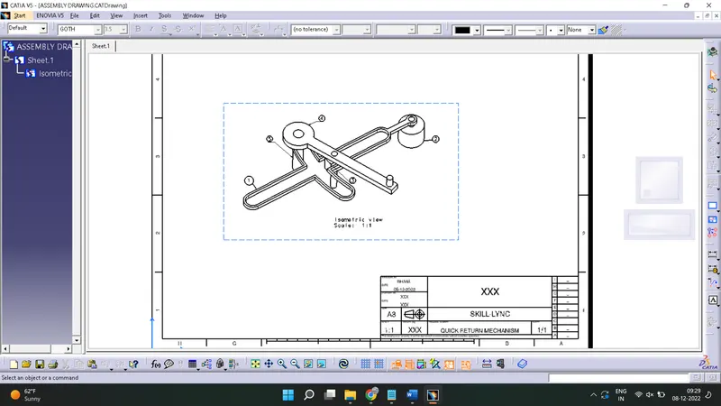
2D Drawing of QUICK RETURN ASSEMBLY:-
CV JOINT:-
PART 1:-
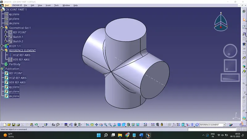
2D DRAWING OF PART 1:-
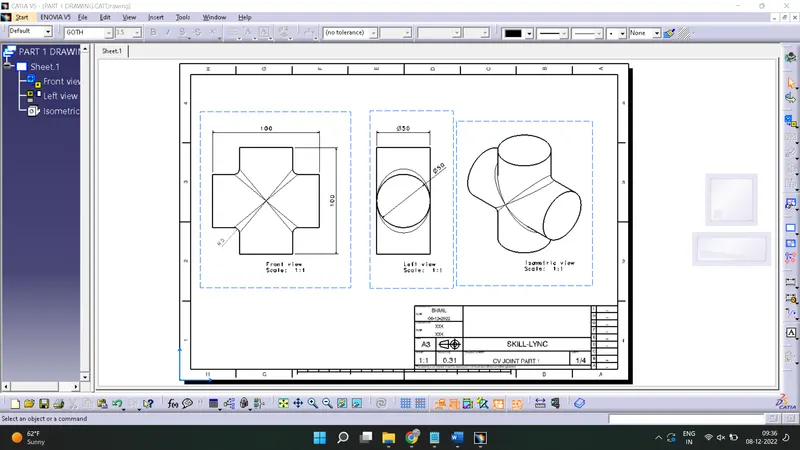
PART 2:-
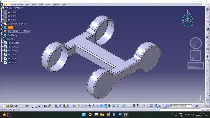
2D DRAWING OF PART 2:-
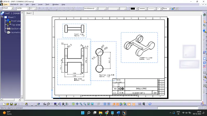
PART 3:-

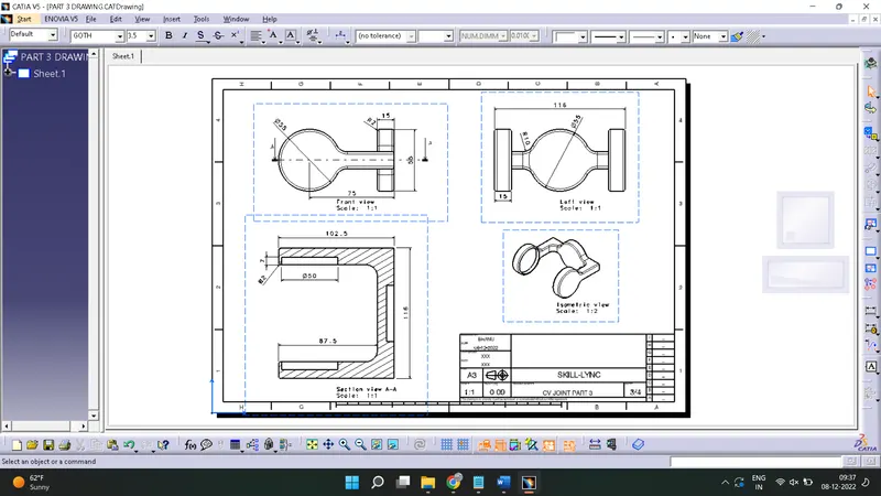
2D DRAWING OF PART 3:-
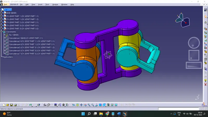
ASSEMBLY OF ALL PARTS (CV JOINT):-
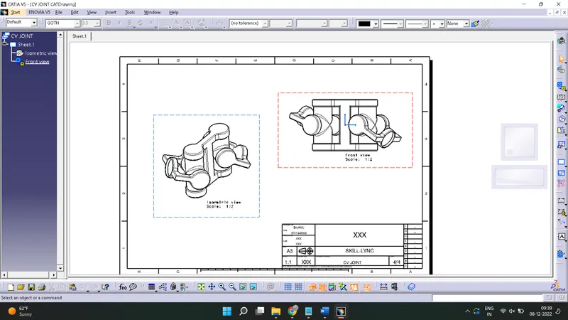
2D DRAWING OF ASSEMBLY:-
CONCLUSION:-
The steps involved in design and assembly of CV joint and quick return mechanism is explained with some reference images of parts and final assembly.