Week 10- Assembly Workbench
Title- Assembly Workbench
Aim - To create assembly for Quick return mechanism and CV Joint.
Objectives:-
- To create the individual part files according to 2D diagrams of the components are provided.
- To create a complete assembly of those part files in the assembly workbench
- To create the 2D drawing of parts and assembly using drafting workbench.
Introduction-
1. Quick Return Mechanism-
A quick return motion mechanism is used in the shaper and slotter machine in which the circular motion is converted into reciprocating motion so that the slider moves forward and backwards. In the forward direction, the cutting process occurs while in return there is no such cutting.
Quick Return Mechanism Types: There are three types of Quick return mechanism.
- Whitworth Quick Return mechanism
- Crank and Slotted Link Mechanism and
- Hydraulic Drive
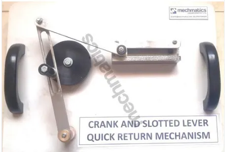
2. CV Joint
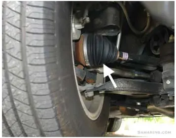
All front-wheel drive cars have Constant Velocity joints or CV joints on both ends of the drive shafts (half shafts). Inner CV joints connect the drive shafts to the transmission, while the outer CV joints connect the drive shafts to the wheels. Many rear-wheel drive and four-wheel drive cars as well as trucks also have CV joints.
The CV joints are needed to transfer the torque from the transmission to the drive wheels at a constant speed, while accommodating the up-and-down motion of the suspension. In front-wheel drive cars, CV joints deliver the torque to the front wheels during turns. There are two most commonly used types of CV joints: a ball-type and a tripod-type. In front-wheel drive cars, ball-type CV joints are used on the outer side of the drive shafts (outer CV joints), while the tripod-type CV joints are mostly used on the inner side (inner CV joints)
Workbech Required -
- Part Modelling
- Assembly
- Drafting
Methodology-
- Part Modelling- Create a solid part model using given input dimensions
- Assembly-
Assembly modeling is the process of creating designs that consist of two or more components assembled together at their respective work positions. The components are brought together and assembled in Assembly Design workbench by applying suitable parametric assembly constraints to them. The assembly constraints allow you to restrict the degrees of freedom of components on their respective work positions. The assembly files in CATIA are called Product files. There are two methods to invoke the Assembly Design workbench of CATIA. The primary method to start a new product file is by selecting File > New from the menu bar to open the New dialog box From this dialog box select Product, as shown in Figure 11-1. The other method of invoking the Assembly Design workbench is by choosing Start > Mechanical
Design > Assembly Design from the menu bar.
Types of Assembly Design Approach:-
In CATIA you can create assembly models by adopting two types of approaches. The first design approach is the bottom-up approach, and the second one is the top-down approach. Both these design approaches are discussed below
- Bottom-up Assembly
The bottom-up assembly is the most preferred approach for creating assembly models. In this of approach, the components are created in the Part Design workbench as (*.CATPart) file. Then the product (*.CATProduct) file is started and all the previously created components are inserted and placed in it using the tools provided in the Assembly Design workbench.
After inserting each component, constraints are applied to position them properly in the 3D space with respect to other components
- Top-down Assembly
In the top-down assembly design approach, components are created inside the Assembly Design workbench. Therefore, there is no need to create separate part files of the components. This design approach is completely different from the bottom-up design approach. Here you have to start the product file first and then, one by one, create all components. Note that even though the components are created inside the product file, they are saved as individual part files and can be opened separately later.
- Drafting- Create drawing of assembly and part individually.
1. QUICK RETURN MECHANISM
A quick return mechanism is an apparatus to produce a reciprocating motion in which the time taken for travel in return stroke is less than in the forward stroke.
It is driven by a circular motion source (typically a motor of some sort) and uses a system of links with three turning pairs and a sliding pair.
There are three types of Quick return mechanism:
- Whitworth Quick Return mechanism.
- Crank and Slotted Link Mechanism and.
- Hydraulic Drive.
Procedure of creating parts:
- First create all parts of CV joints and QRM with help of drawings provided
- All parts to be created separately in part work bench
- After creating all parts individualy we assemble them together in single product in assembly workbench
- Using constriants we assemble all parts together and create CV joint and QRM.
Part Body 1 :
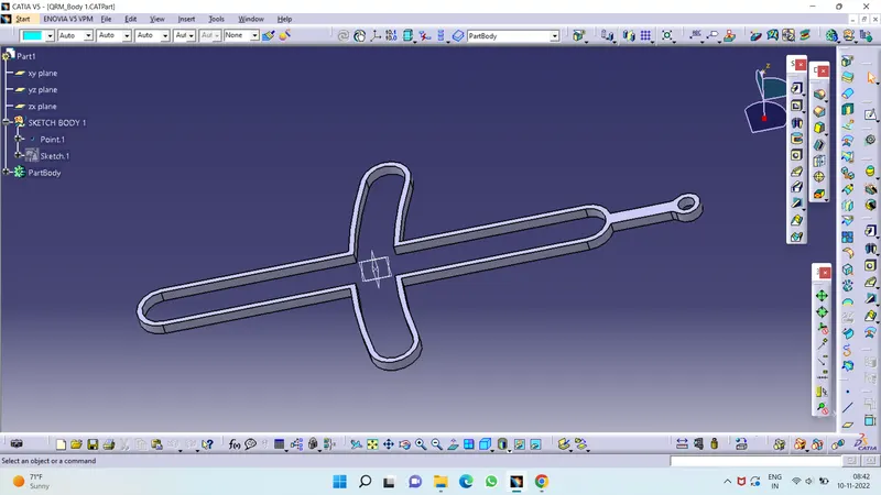
2D DRAWING :
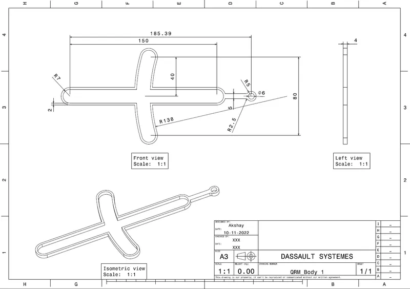
Part Body 2 :
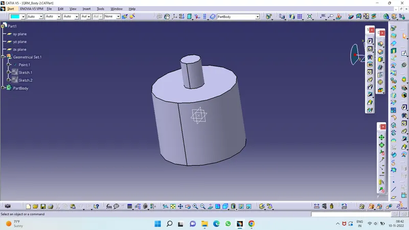
2D DRAWING :
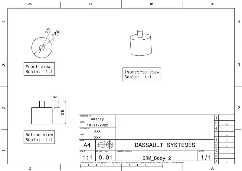
Part Body 3 :
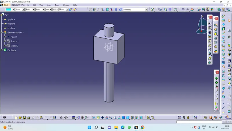
2D DRAWING :
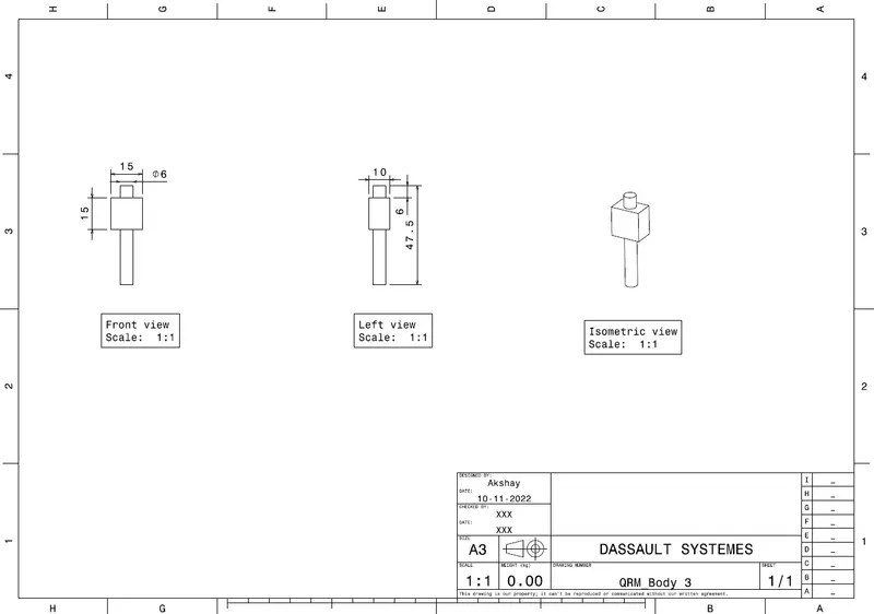
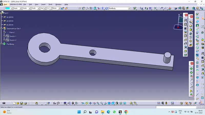
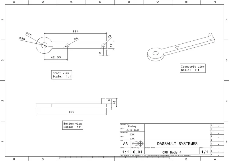
Part Body 4 :
2D DRAWING :
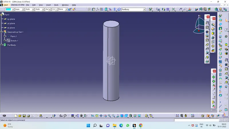
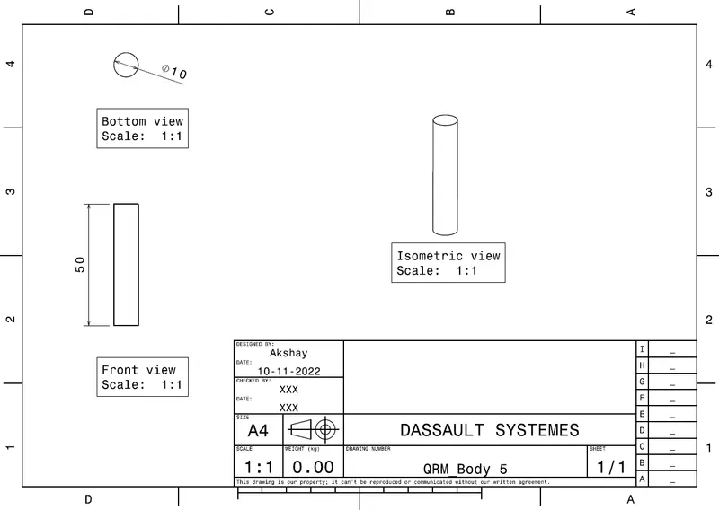
Part Body 5 :
2D DRAWING :
Product Assembly :
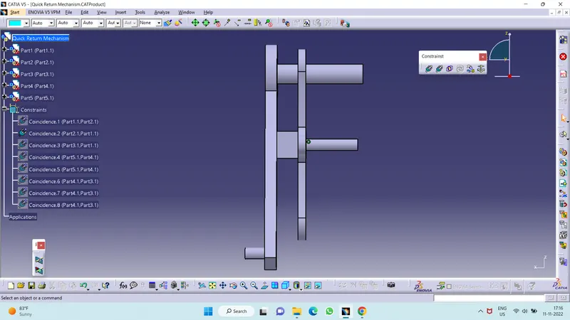
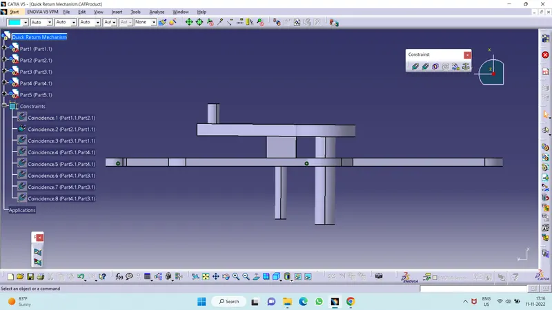
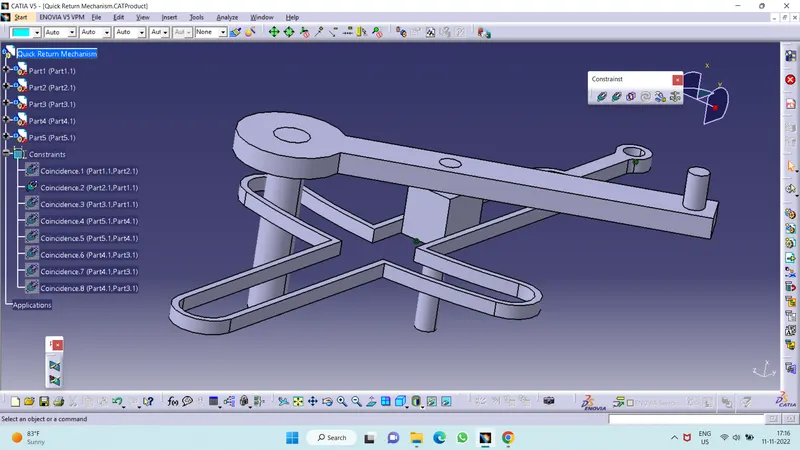
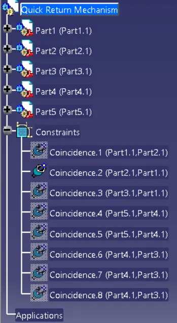
Tree Structure :
2. CV JOINT
Constant-velocity joints (also known as homokinetic or CV joints) allow a drive shaft to transmit power through a variable angle, at
Constant rotational speed, without an appreciable increase in friction or play.
They are mainly used in front wheel drive vehicles. Modern rear wheel drive cars with independent rear suspension typically use CV joints at the ends of the rear axle halfshafts and
increasingly use them on the drive shaft.
Function :
Besides just holding the drive shaft in place, the CV joints also transfer power to the wheels from the transmission.
Basically, they ensure that when you press on the gas, your wheels will turn. If the CV joint is not working properly, it may affect the way your vehicle
handles.
Often you will hear a popping or a clunk sound when shifting, which indicates something is wrong.
If the joint breaks, it can stop the car from moving and can cause severe damage, making it essential component in your vehicle that needs to be kept in
good condition.
Procedure of creating parts:
- First create all parts of CV joints and QRM with help of drawings provided
- All parts to be created separately in part work bench
- After creating all parts individualy we assemble them together in single product in assembly workbench
- Using constriants we assemble all parts together and create CV joint and QRM.
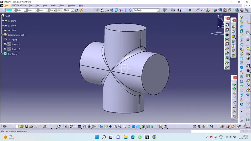
Part Body 1 :
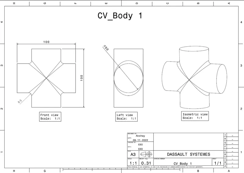
2D DRAWING :
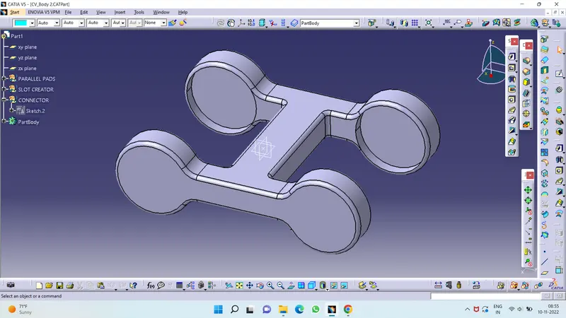
Part Body 2 :
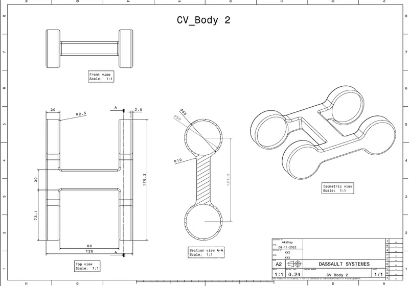
2D DRAWING :
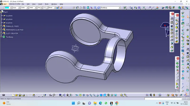
Part Body 3 :
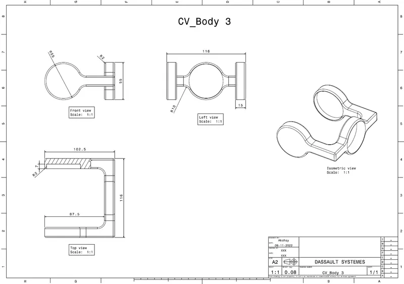
2D DRAWING :
Product Assembly :
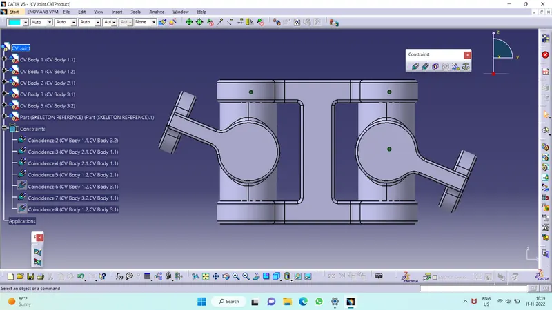
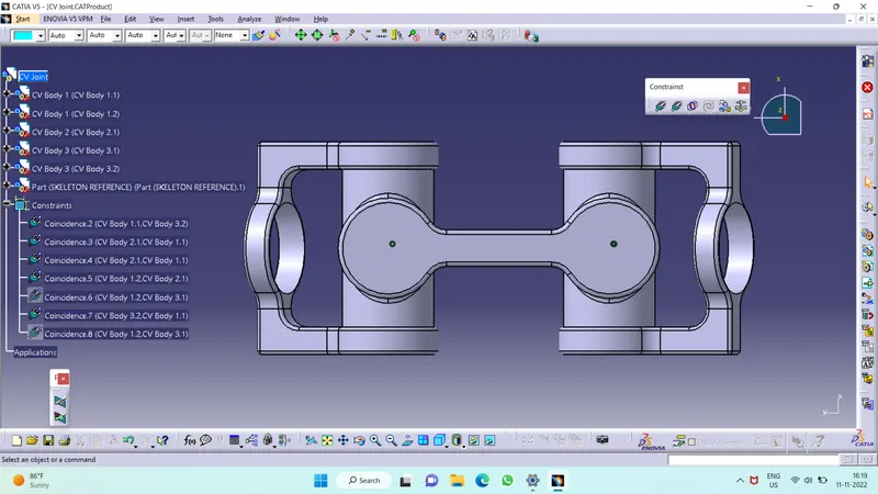
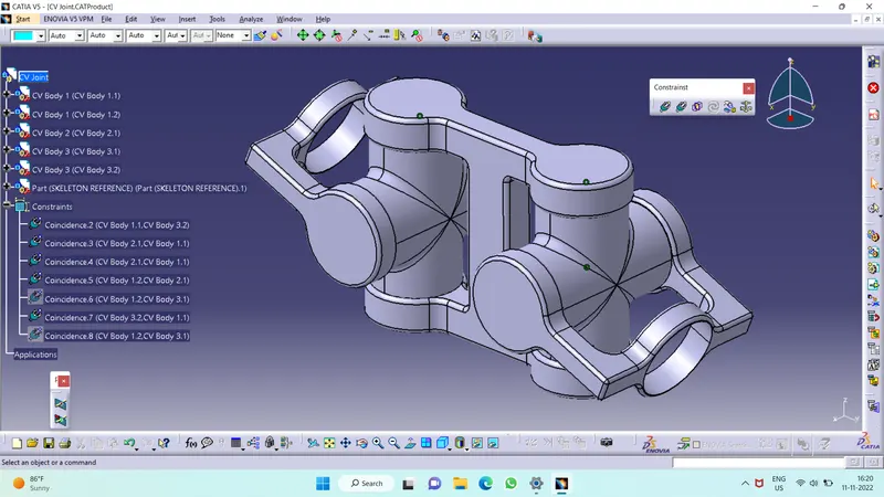
Tree Structure :
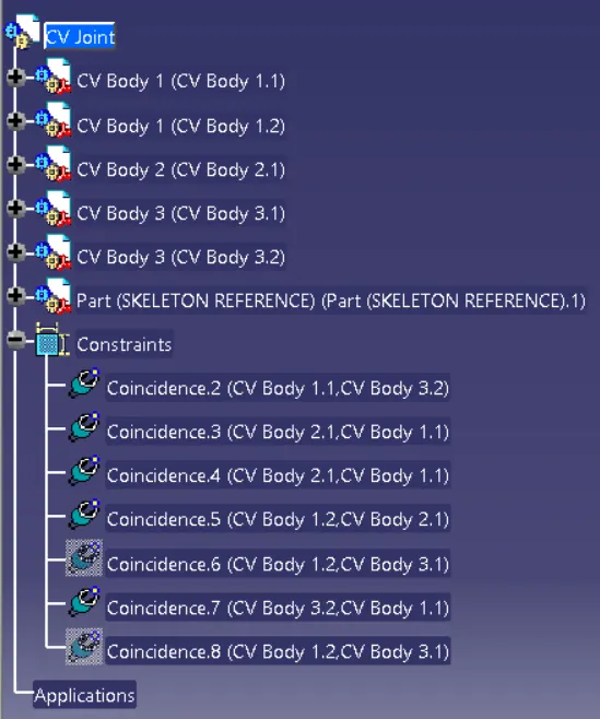
CONCLUSION :
Thus, the CV joint and Quick return mechanism parts were modelled in part workbench and assembled in assembly workbench in CATIA.