Week 10- Assembly Workbench
ASSEMBLY WORKBENCH
AIM- To create 2 assemblies according to the provided 2D drawing. First create all the part files and then assemble them together.
THEORY-
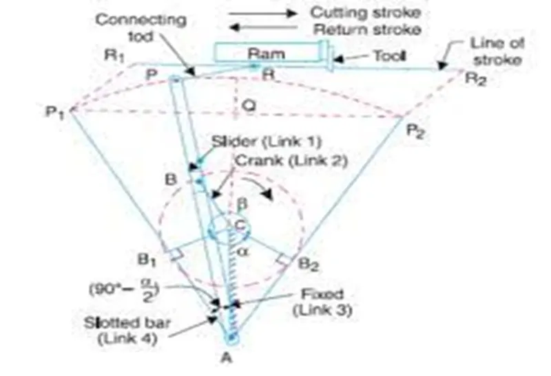
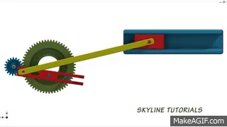
QUICK RETURN MECHANISM-A quick return mechanism is an apparatus to produce a reciprocating motion in which the time taken for travel in return stroke is less than in the forward stroke. It is driven by a circular motion source (typically a motor of some sort) and uses a system of links with three turning pairs and a sliding pair.
APPLICATION-
Quick return mechanisms are found throughout the engineering industry in different machines:
- Shaper
- Screw press
- Power-driven saw
- Mechanical actuator
- revolver mechanisms
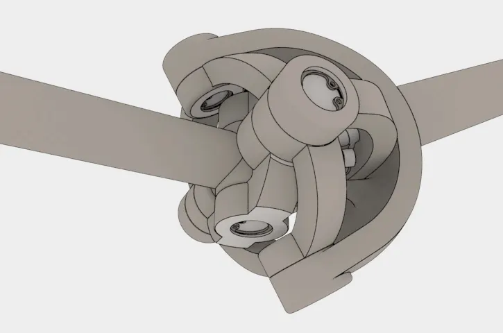
CONSTANT VELOCITY JOINT-
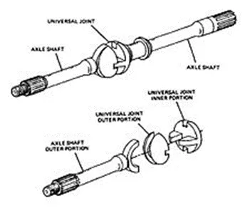
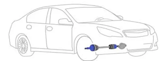
Constant-velocity joints (also known as homokinetic or CV joints) allow a drive shaft to transmit power through a variable angle, at constant rotational speed, without an appreciable increase in friction or play. They are mainly used in front wheel drive vehicles. Modern rear wheel drive car with independent rear suspension typically use CV joints at the ends of the rear axle half shafts and increasingly use them on the drive shaft.
ASSEMBLY WORKBENCH-
Assembly workbench is one of the most powerful work benches in CATIA for the reason that components that are designed in multiple workbenches gets assembled here. Typically, a car is made of 30,000 parts from small nuts to tyres and this cannot be made into a single product without the help of Assembly workbench. We can also perform various analyses like Clash & Clearance, Dependencies & Degree of freedom in this workbench. Let us see an overview of Types of constraints and methods to apply them in this article. To enter the Assembly workbench, Start > Mechanical Design > Assembly Design.
TYPES OF ASSEMBLY DESIGN APPROACH IN CATIA
you can create assembly models by adopting two types of approaches. The first design approach is the bottom-up approach, and the second one is the top-down approach. Both these design approaches are discussed below.
BOTTOM DOWN ASSEMBLY
The bottom-up assembly is the most preferred approach for creating assembly models. In this of approach, the components are created in the Part Design workbench as (*.CAT Part) file. Then the product (*.CAT Product) file is started and all the previously created components are inserted and placed in it using the tools provided in the Assembly Design workbench. After inserting each component, constraints are applied to position them properly in the 3D space with respect to other components. Adopting the bottom-up approach gives the user the opportunity to pay more attention to the details of the components as they are designed individually. Because the other components are not present in the same window, it becomes much easier to maintain a relationship between
the features of the current component. This approach is preferred for large assemblies, especially those having intricate individual components.
TOP-DOWN ASSEMBLY
In the top-down assembly design approach, components are created inside the Assembly Design workbench. Therefore, there is no need to create separate part files of the components. This design approach is completely different from the bottom-up design approach. Here you have to start the product file first and then, one by one, create all components. Note that even though the components are created inside the product file, they are saved as individual part files and can be opened separately later. Adopting the top-down design approach gives the user the distinctive advantage of using the geometry of one component to define the geometry of the other. Here the construction and assembly of the components takes place simultaneously. As a result of this, the user can view the development of the product in real time. This design approach is highly preferred, while working on a conceptual design or a tool design where the reference of previously created parts is required to develop a new part.
CONSTRAINTS IN ASSEMBLY WORKBENCH
Constraints allow you to position mechanical components correctly in relation to the other components of the assembly. You can see the Constraints tool bar in any typical Assembly workbench, if it is not visible try to restore all the positions of the toolbars. You can also navigate to View - Tool bars and then select the Constraints toolbar.
FIX CONSTRAINT
In this constraint type all the Degrees of freedom are constrained. Fixing a component means preventing the component from moving from its parents during the update operation. When an assembly is started the right approach would be to start with fixing a component. Fixing a part in Assembly works on two basic methods, one is with respect to absolute position and the other is relative Position. In absolute position the geometrical origin of the part is fixed, this is also referred to as "Fix in space”. In relative position it is fixed with respect to other components, this is also referred to as "Fix"
COINCIDENCE CONSTRAINT
A coincident constraint causes two points to coincide, or a point to lie anywhere on an object or the extension of an object. It has infinite number of solutions, so this is a primary level constraint. This constraint allows rotation and translation along the axis through which the parts were made coincidence.
CONTACT CONSTRAINT
The name defines itself; it creates a constraint that helps the components to be in contact with each other. Contact-type constraints can be created between two planes or faces. In the below example we have selected the faces in the same way you can try the contact constraints using the plane also.
OFFSET CONSTRAINT
The Offset Constraint is used to place selected elements at an offset distance from each other. It also makes the two planar faces parallel to each other.
FIX TOGETHER
The Fix Together constraint is used to fix the position of the selected components with respect to each other. Once the selected components are fixed together, they can be moved as a single component such that the position of one component with respect to another component remains the same.
ANGLE CONSTRAINT
The Angle Constraint is used to position two geometric elements at a particular angle with respect to each other. You can also use this tool to make two selected elements parallel or perpendicular to each other.
QUICK CONSTRAINT
When you select the Quick constraint the CATIA applies the most appropriate constraint between the selected components. The applied constraints depend on the priority of constraints in the Quick Constraints priority list. This list can be seen by choosing Tools >Options from the menu bar. From the Options dialog box, choose Assembly Design from the Mechanical Design on the left of the Options dialog box. The Quick Constraint priority list will be displayed.
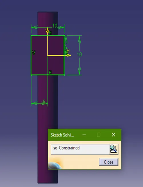
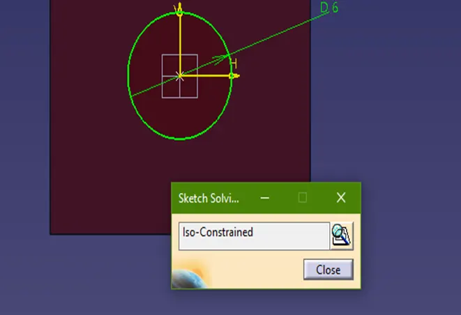
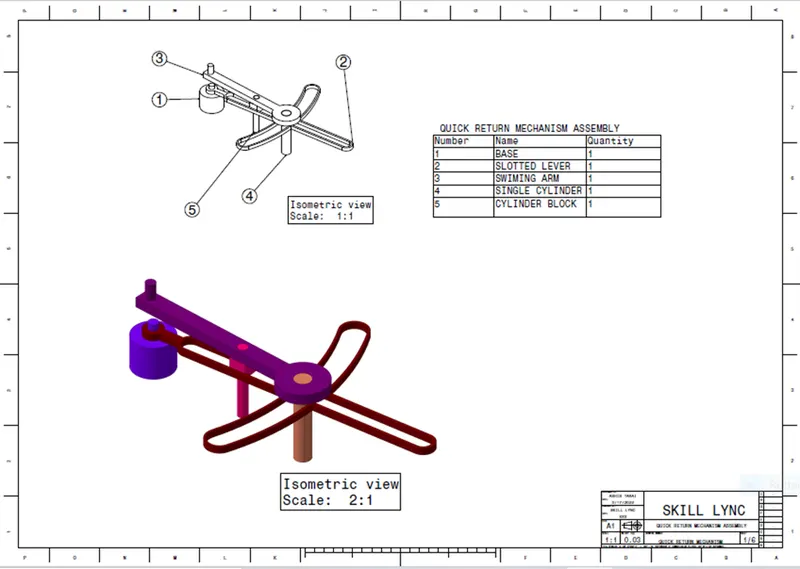
QUICK RETURN MECHANISM ASSEMBLY &ITS PARTS
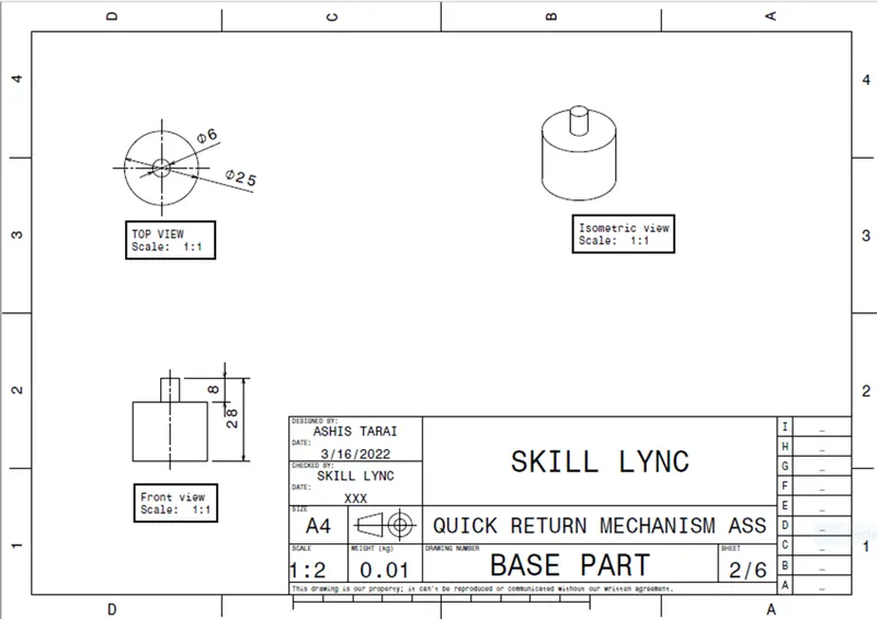
1.BASE PART
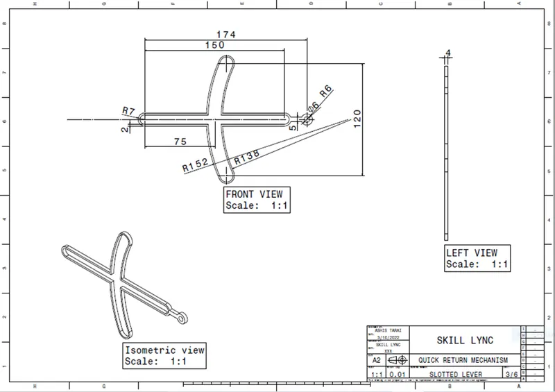
2.SLOTTED LEVER
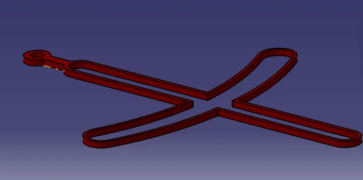
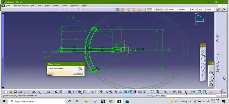
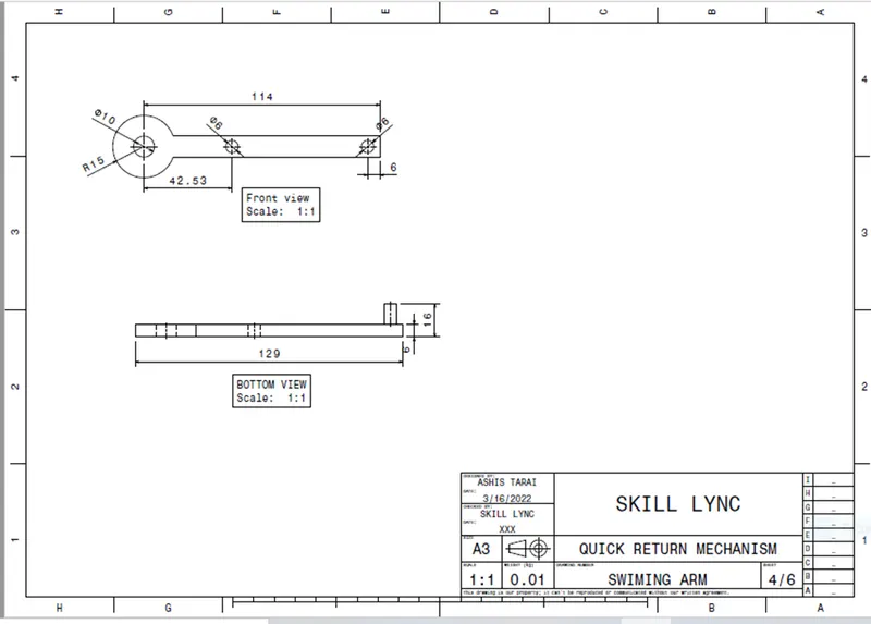
3.SWIMING ARM
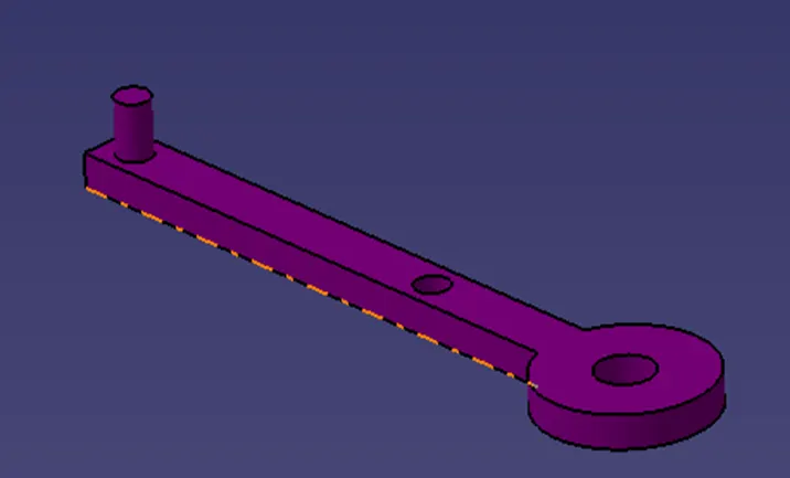
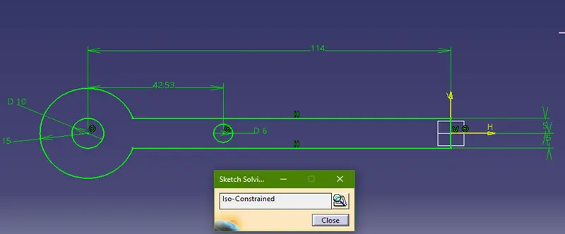
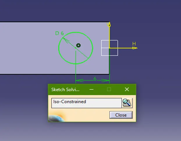
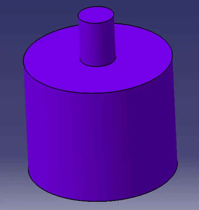
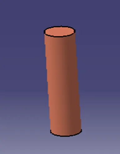
4.SINGLE CYLINDER
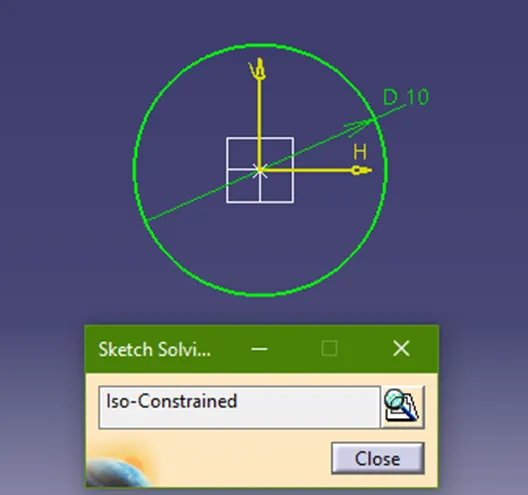
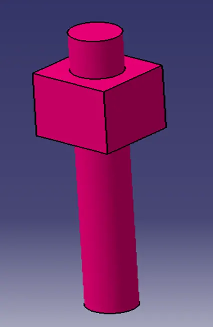
- CYLINDER BLOCK
ASSEMBLY OF QUICK RETURN MOTION MECHANISM
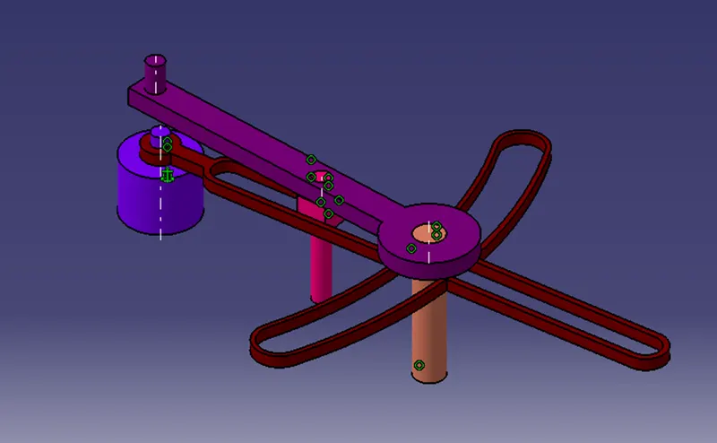
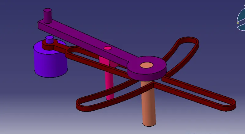
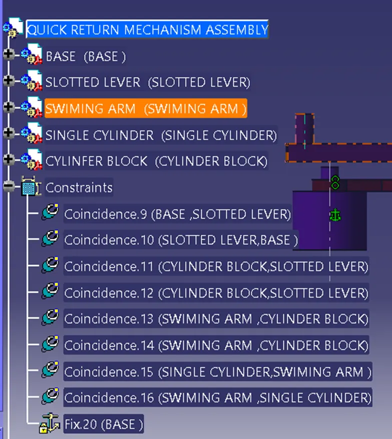
1.Create a new CAT Product and insert all the above part by using existing component command.
2.Add reference element for all part when needed like axis, points.
3.use publication tool to make all the necessary elements like planes, points, axis.
4.make the base part fixed, and using constrain, offset tools assemble each part to one another.
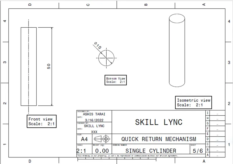
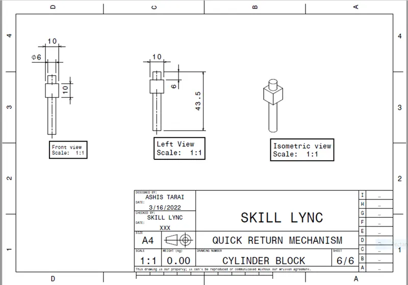
DRAFTING IMGES OF ALL THE PARTS
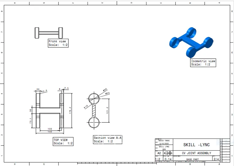
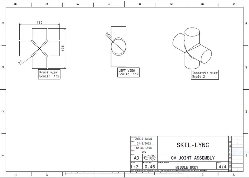
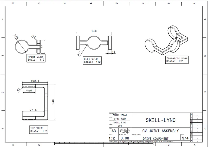
CV JOINT ASSEMBLY&ALL CAT PARTS
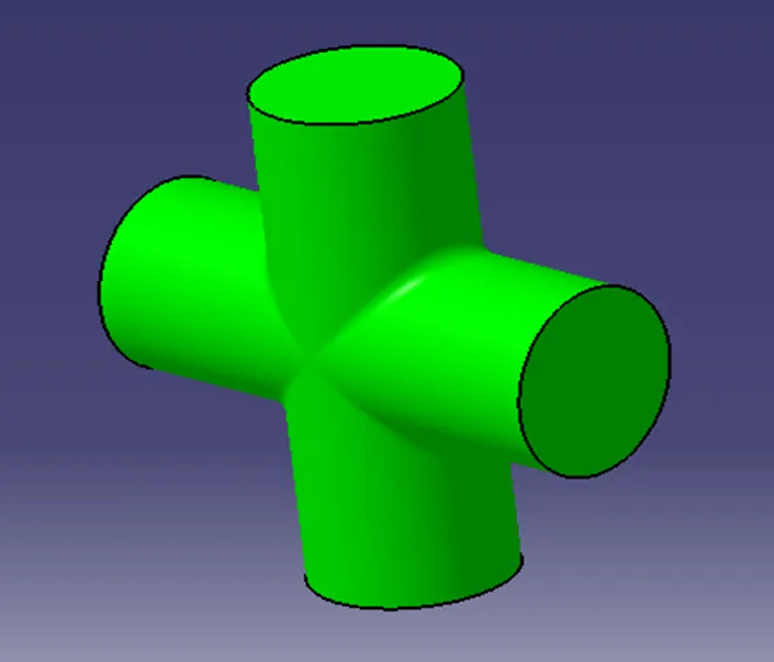
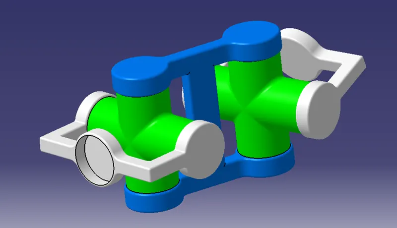
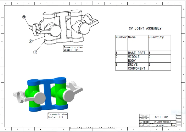
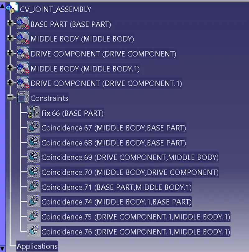
cv joint assembly consist of 5 parts in which few parts are identical which can be copy.
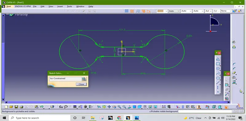
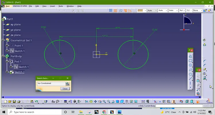
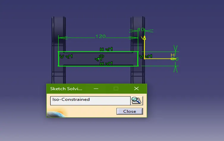
1.BASE PART
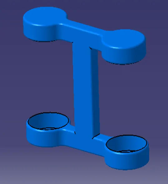
2.MIDDLE PART BODY
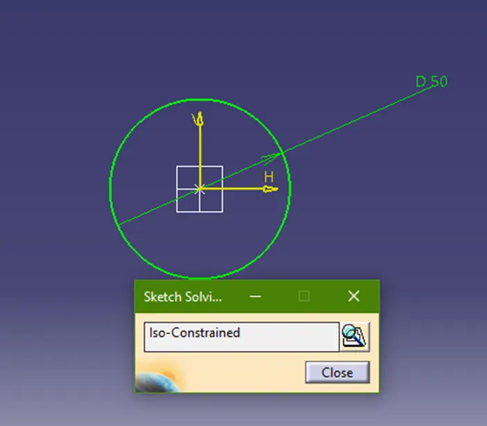
3.DRIVE COMPONENT
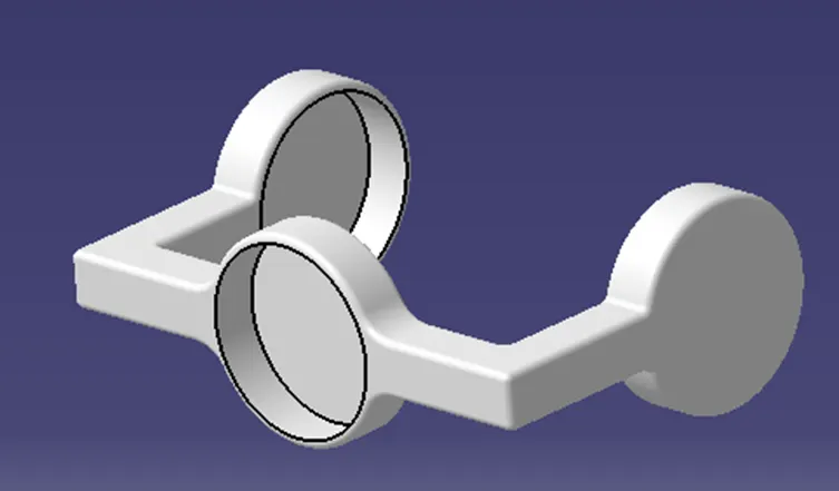
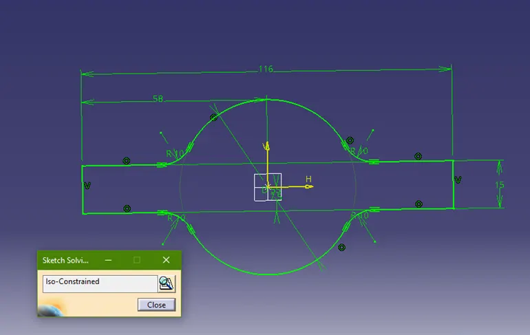
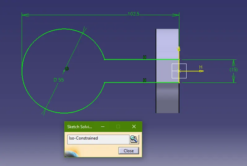
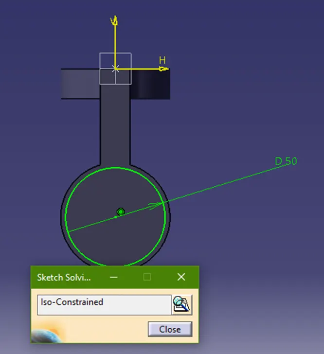
ASSEMBLY OF CV JOINT
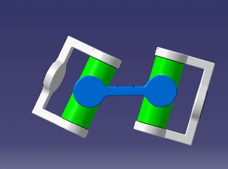
DRAFTING IMAGES OF ALL THE PARTS
CONCLUSION-
All the parts are created in part workbench and assemble is created in assembly workbench successfully. From this challenge we know how to create assembly and assembly workbench all command, like existing component, new part, assembly constraint etc.