Week 10- Assembly Workbench
AIM
To create assembly for quick return mechanism and cv joint.
OBJECTIVES
- To create the individual part files according to 2D diagrams of the components are provided.
- To create a complete assembly of those part files in the assembly workbench.
- To create the 2D drawing of parts and assembly using drafting workbench.
INTRODUCTION
Quick return mechanism:-
It is an apparatus to provide a reciprocating motion in which the time taken for travel in return stroke is less than in the forward stroke. It is driven by a circular motion source and uses system of links with three turning pairs and a sliding pair.
Constant velocity joints:-
CV joints are mechanical joints which allow a drive shaft to transmit power through a variable angle, at constant rotational speed, without an appreciable increase in friction or play. They are mainly used in front wheel drive vehicles. Modern rear wheel drive cars with independent rear suspension typically use CV joints at the ends of the rear axle half shafts and increasingly use them on the drive shaft.
Types of assembly design approach
In CATIA you can create assembly models by adopting two types of approaches. The first design approach is the bottom-up approach and the second one is the top- down approach, and the second one is the top down approach.
Bottom-up assembly:-
The bottom up assembly is the most prefered approach for creating assembly models. In this approach, the components are created in the part design work bench as catpart file. Then the product file is started and all the previously created components are inserted and placed in it using the tools provided in the assembly design workbench. After inserting each component, constraints are applied to position them properly in the 3D space with respect to other componets.
Top down assembly:-
In the top-down assembly design approach, components are created inside the assembly design workbench. There fore there is no need to create seperate part files of the components. This design approach is completely different from the bottom-up design approach. Here you have to start the product file first and then, one by one. Create all components. Note that even though the components are created inside the product file, they are saved as individual part files and can be opened seperately later.
QUICK RETURN MECHANISM
- Here bottom-up assembly is used.
- Initially individual parts are created.
- Then product file is created and individual part is added.
- Here coincide. contact and offset constraints are used.
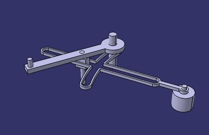
figure 1. isometric view
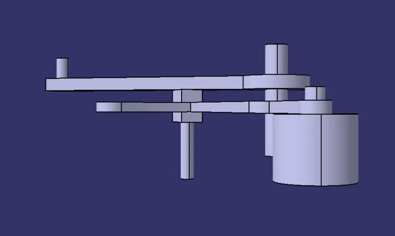
figure 2. front view
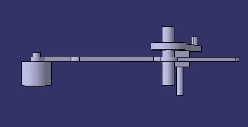
figure 3. right side view
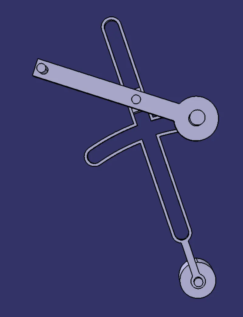
figure 4. top side view
The parts in the quick return mechanism:-
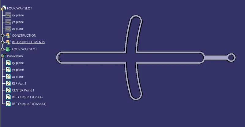
figure 5. four way slot
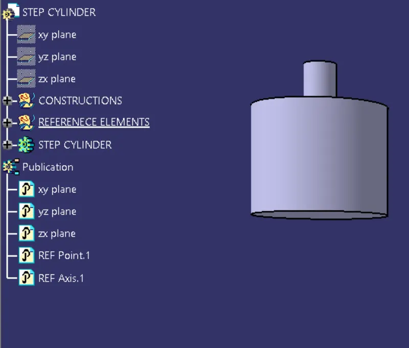
figure 6. step cylinder
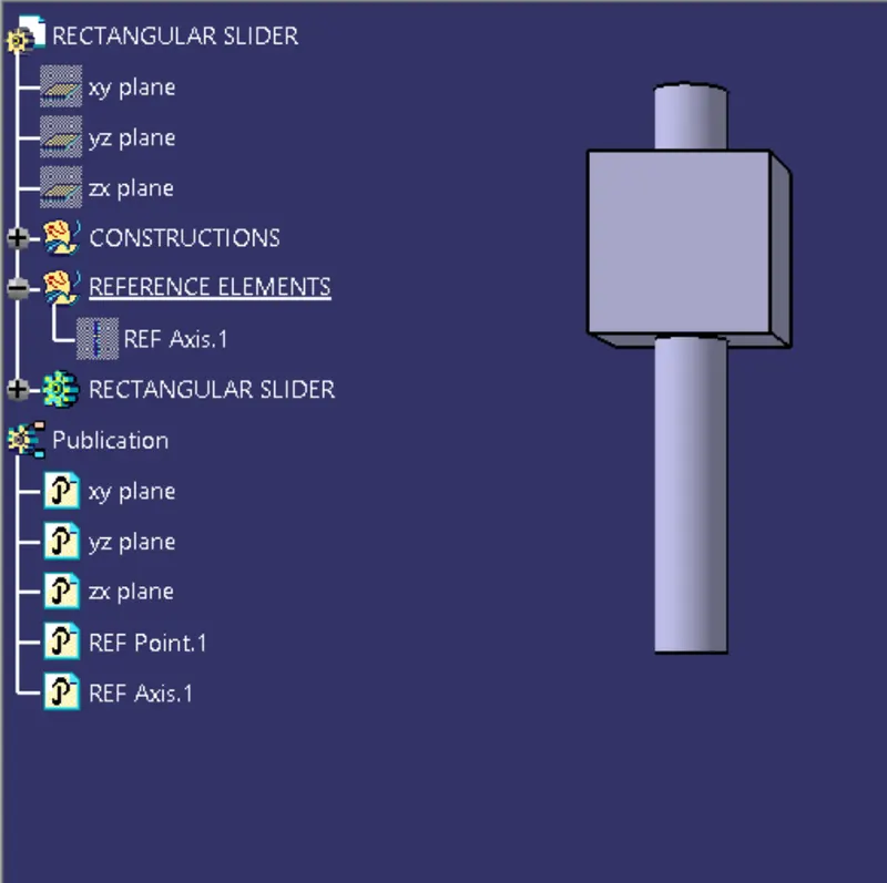
figure 7. rectangular slider
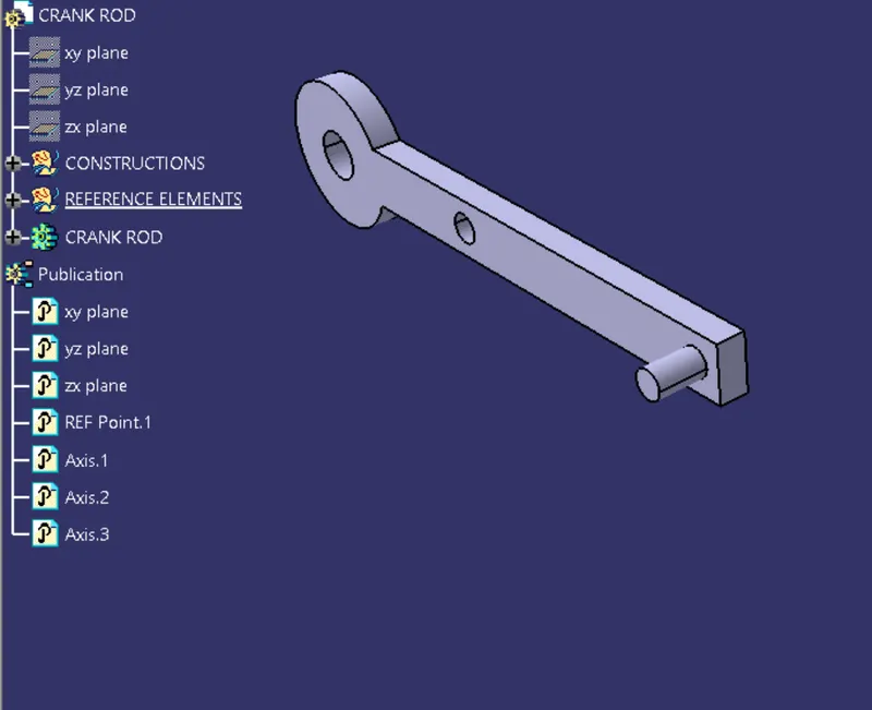
figure 8. crank rod
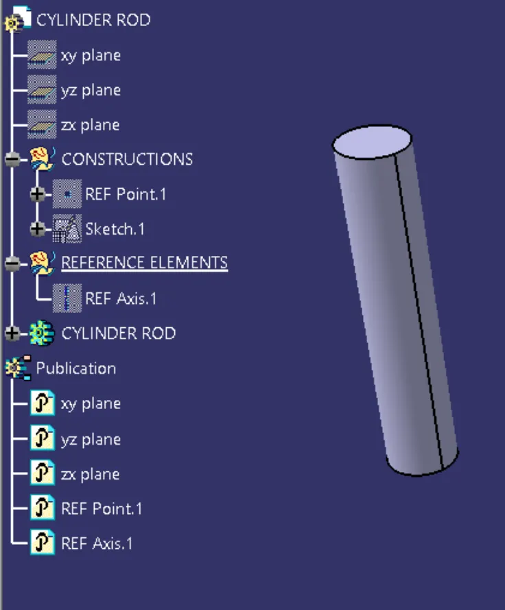
figure 9. cylinder rod
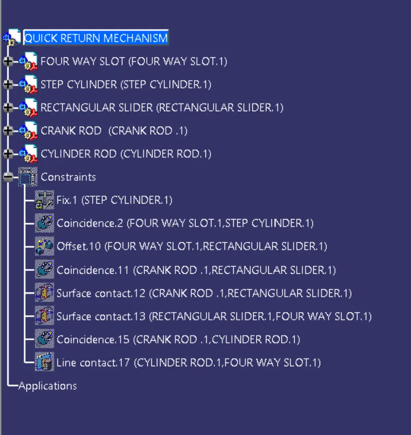
figure 10. tree structure
Drawings of quick return mechanism:-
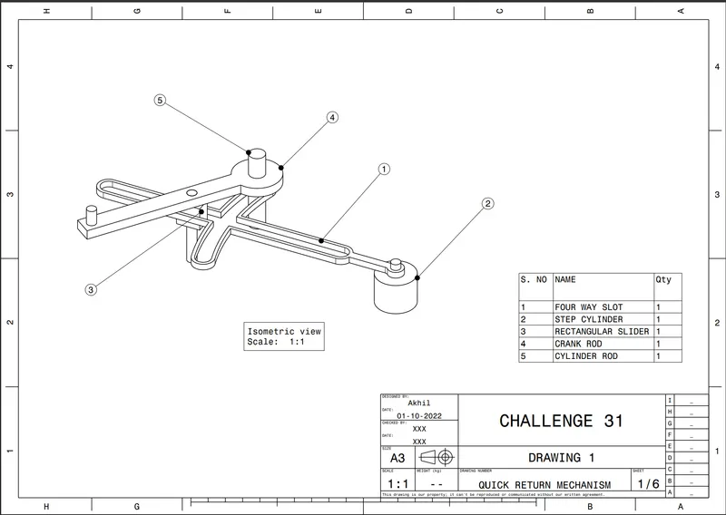
figure 11. drawing 1
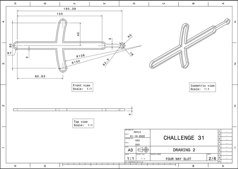
figure 12. drawing 2
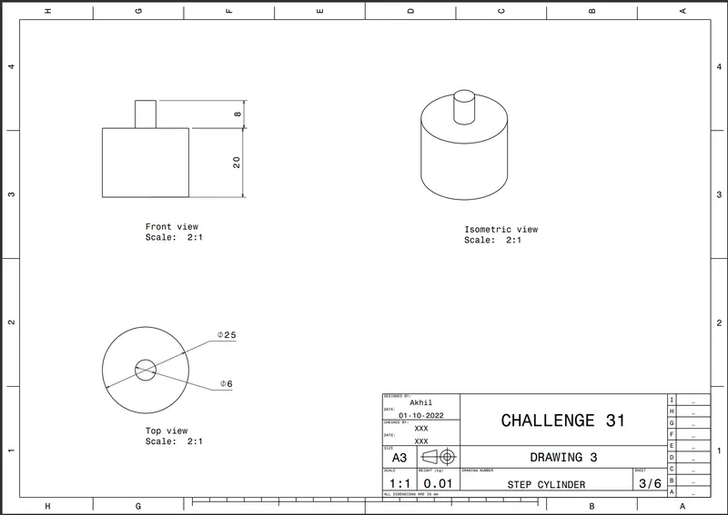
figure 13. drawing 3
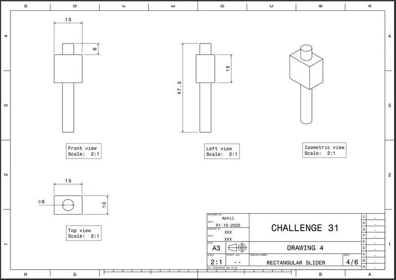
figure 14. drawing 4
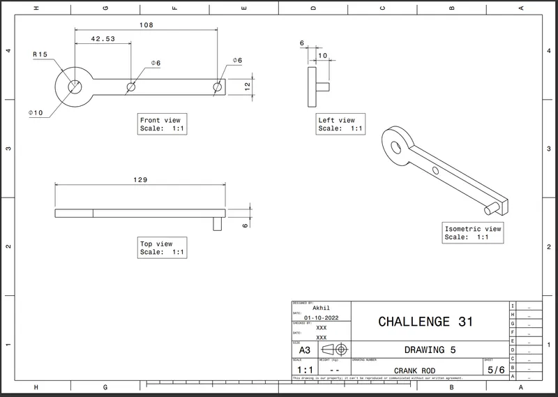
figure 15. drawing 5
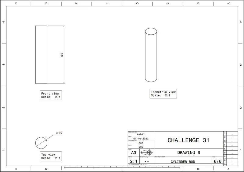
figure 16. drawing 6
CV JOINT
- Here bottom-up assembly is used.
- Initially individual parts are created.
- Then product file is created and individual part is added.
- Here coincide. contact and offset constraints are used.
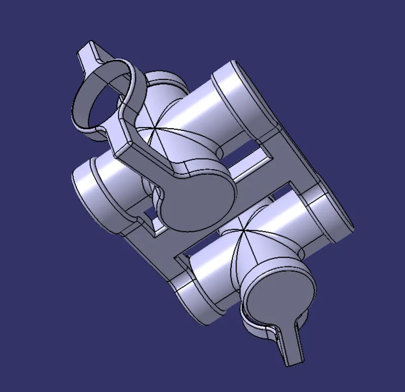
figure 17. isometric view
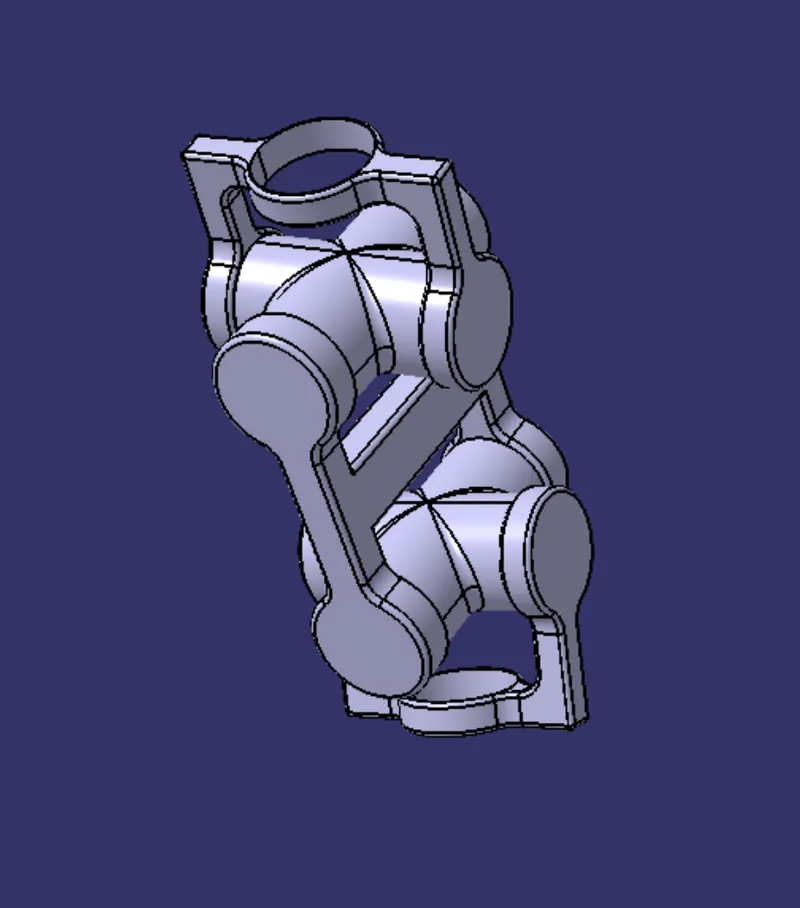
figure 18. front view
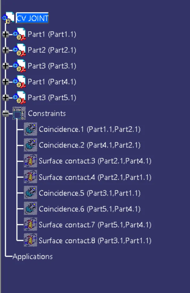
figure 19. tree structure
Parts of CV joint
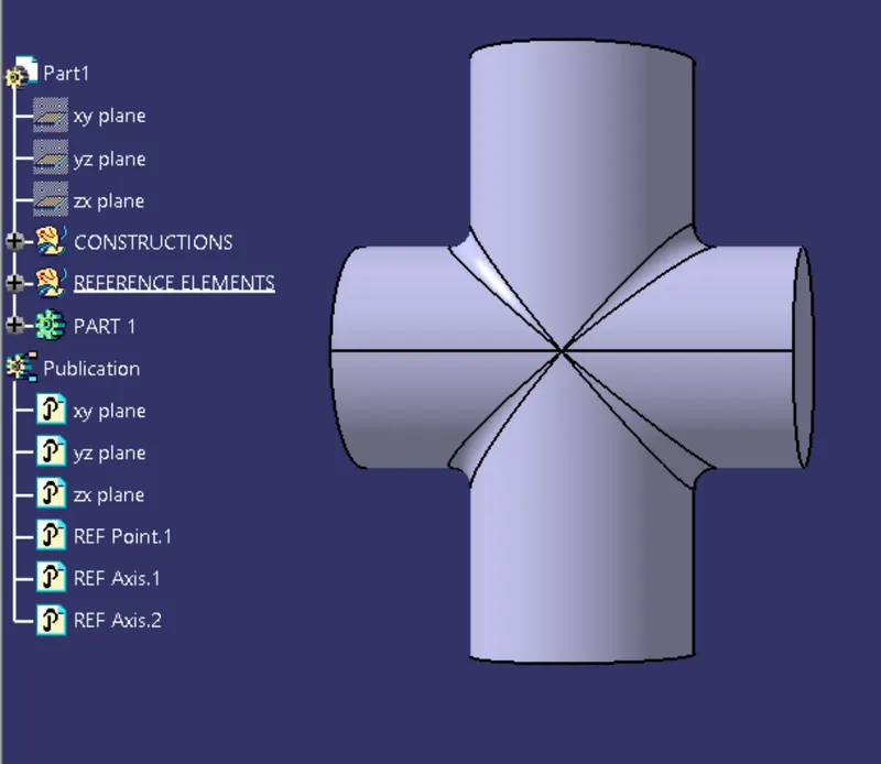
figure 20. part 1
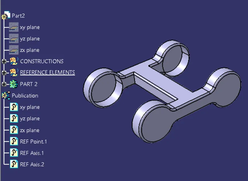
figure 21. part 2
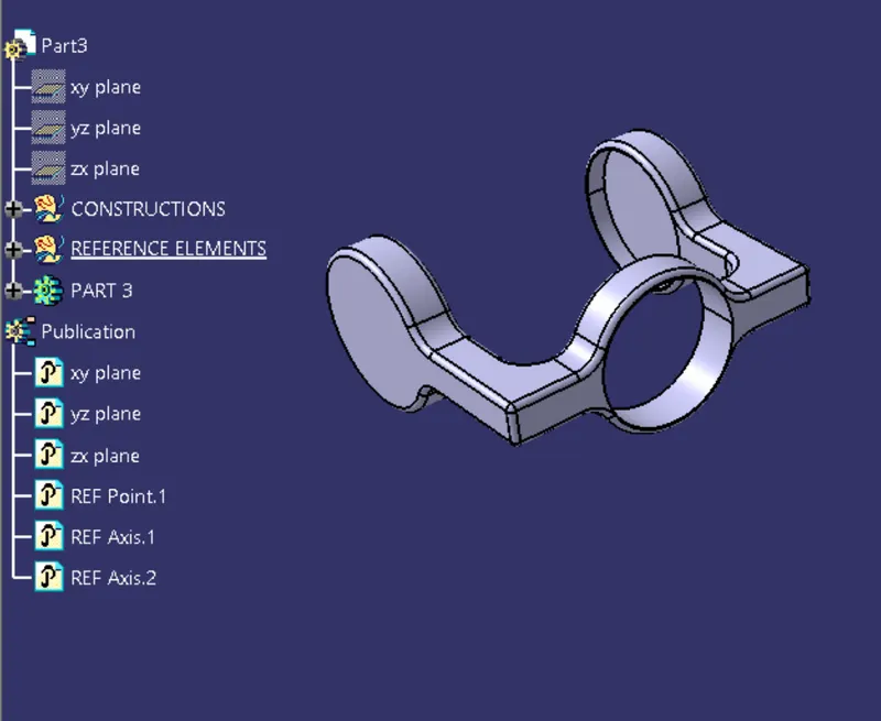
figure 22. part 3
Drawings of CV joint
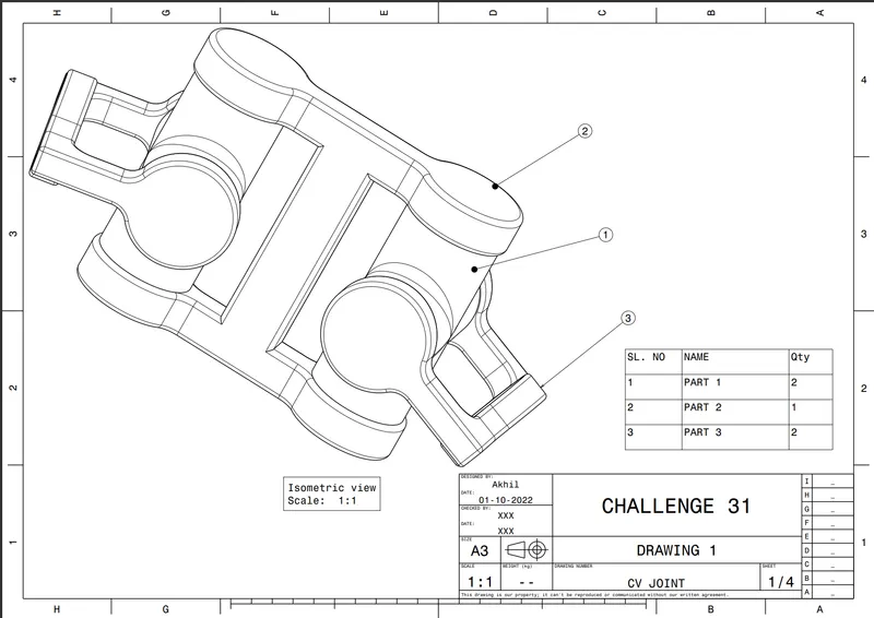
figure 23 . drawing 1
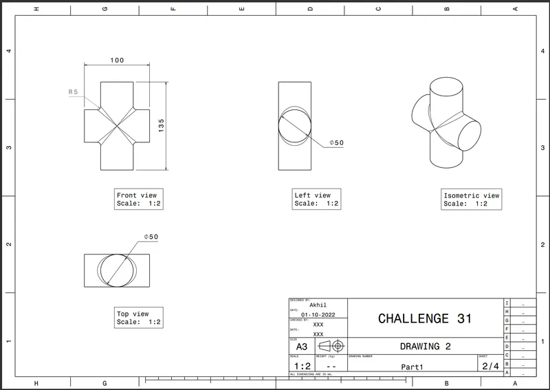
figure 24. drawing 2
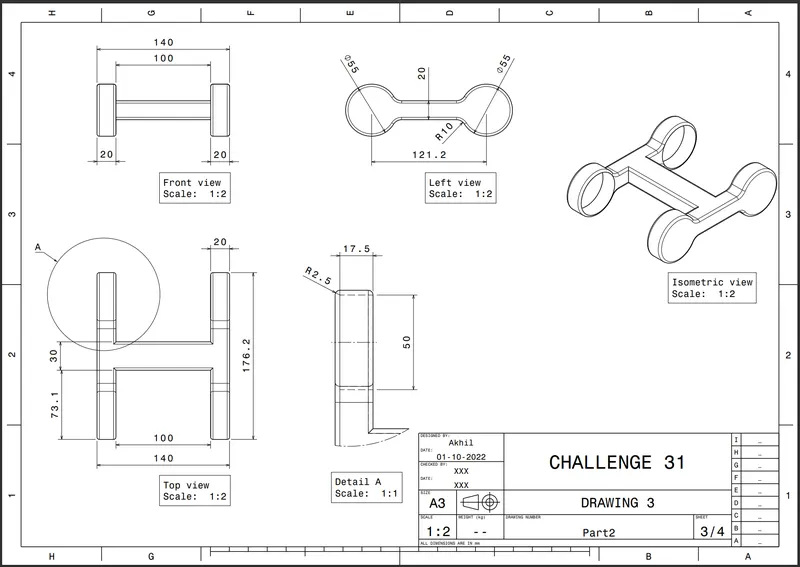
figure 25. drawing 3
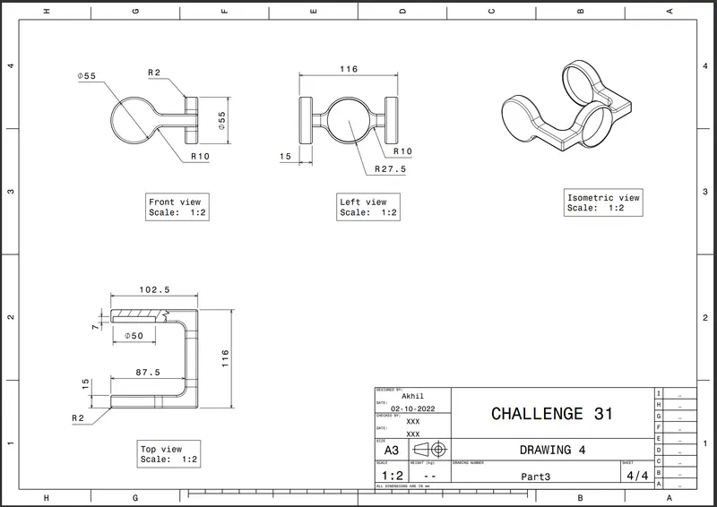
figure 26. drawing 4
CONCLUSIONS
Assembly for quick return mechanism and CV joint are created.