Week 10- Assembly Workbench
Week 10- Assembly Workbench
AIM
Create individual part from the given 2D component diagram and then create Assembly from these parts. Also create 2D drawings using Drafting tools.
Procedure
- First individual part models are created by creating iso constraint sketch and extruded using Pad, multipad, Shaft or boolean operation, mirror, fillets etc. features.
- To assemble all the parts, new product file is created in the Catia V5.
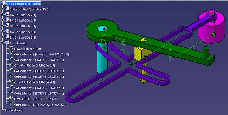
- New part is inserted as a Reference skeleton, which contains a reference point. This point is given fixed constraint.
- Then all individual components are added in file using existing component.
- For each part, reference point is created and Axis at the mating position. All the the reference points, planes and axis are published.
- First part is aligned with the fixed reference point as per required orientation.
- Then next part is constraint with previously constrained parts or fixed reference. This procedure is repeated for all the components in the assembly.
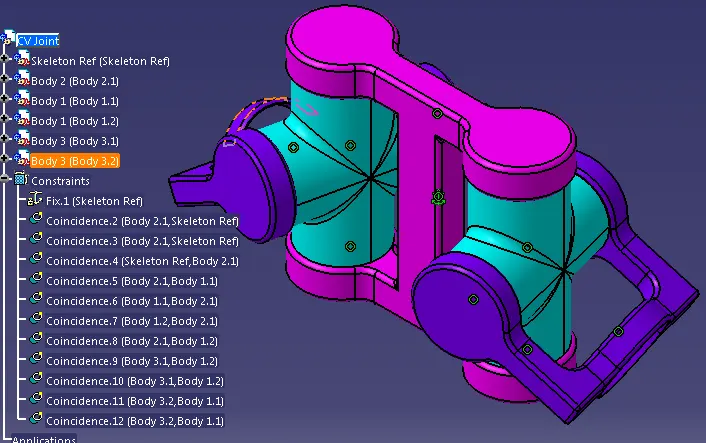
- Common constraints used for assembly are Fixed Constraint, Coincidence Constraint to align point or axis or plane, Offset constraint to align at certain distance away from reference, Contact constraint.
- Assembly is saved using Save managament.
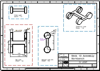
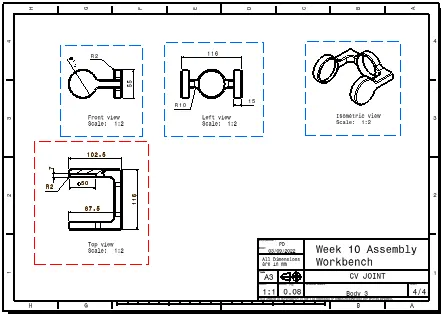
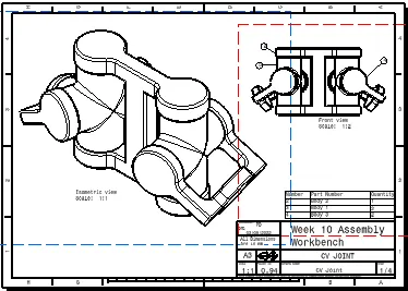
- 2D drawings are created using Drafting. Drawing are created for each indivual component and assembly seperately as per given input.
- Numbering is provided to parts in assembly to create BOM table and ballooning in drafting.
OUTPUT
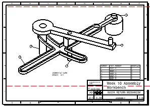
- Quick Return Mechanism
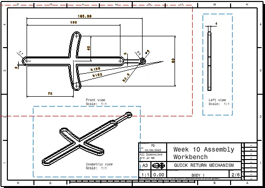
Body 1 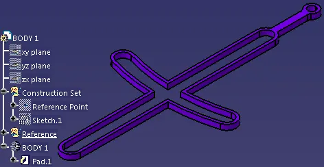
Body 2 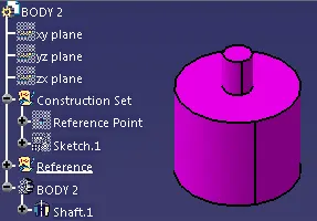
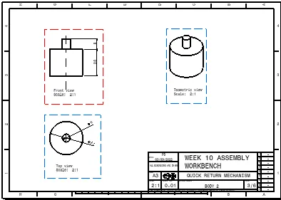
Body 3 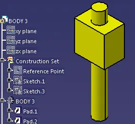
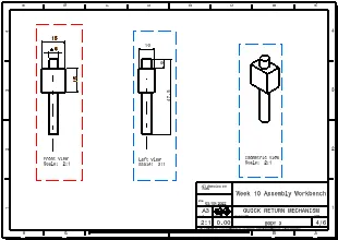
Body 4 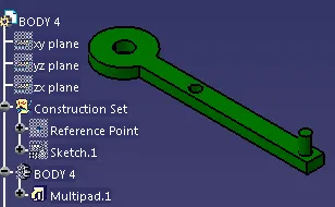
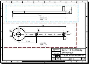
Body 5 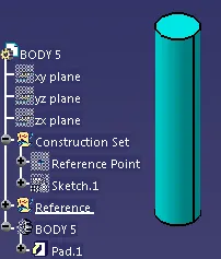
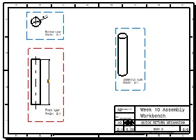
Assembly 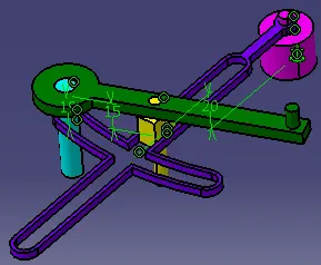
- CV Joint
Body 1 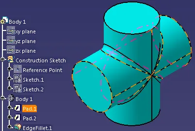
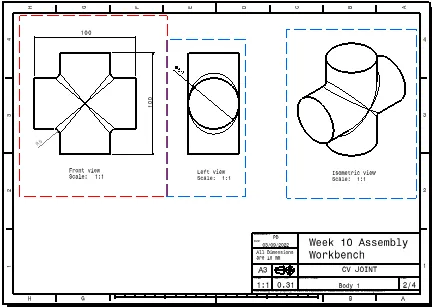
Body 2 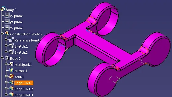
Body 3 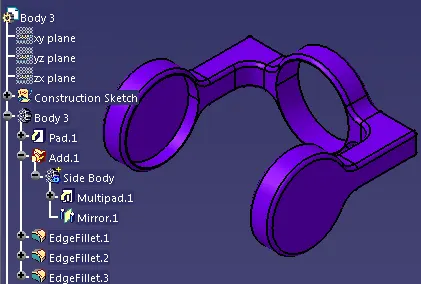
Assembly 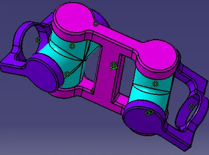
Conclusion
All the individual parts and Assembly is created from given 2D drawings in Catia V5 using Product workbench. Coincidence, offset and fixed constraints are used to assemble parts. Also Drafting tool is used to create 2D drawings.