Week 10- Assembly Workbench
DESIGN AND ASSEMBLY OF QUICK RETURN MECHANISM
AIM:
To create 2 assemblies according to the content covered in the course videos. You will be provided with 2D diagrams of the components and you will have to first create the individual part files and then create a complete assembly of those part files in the assembly workbench. After creating the assembly make use of the drafting tools to create a 2D drawing similar to the one given in the assignment folder.
SOFTWARE REQUIRED:
CATIA_V5 R21
PROCEDURES:
- initially, we creating a solid model by using given inputs( part dimensions).
- Once we get it, and we go to the assembly design workbench.
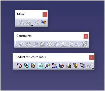
- Assembly design tool commands
QUICK RETURN MECHANISM
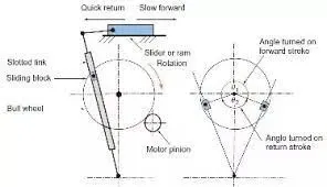
A quick return mechanism is an apparatus to produce a reciprocating motion in which the time taken for travel in return stroke is less than in the forward stroke. It is driven by a circular motion source (typically a motor of some sort) and uses a system of links with three turning pairs and a sliding pair.
PART MODELING:
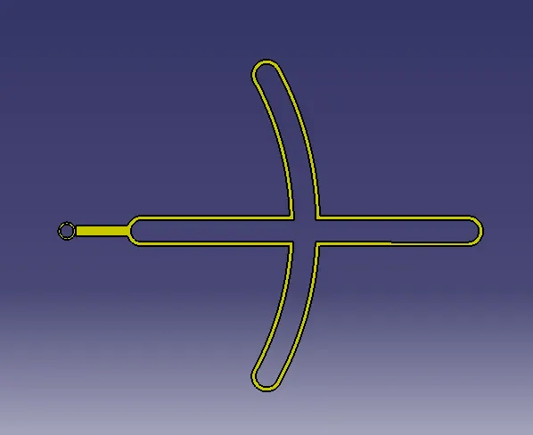
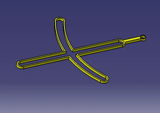
There are 5 Parts are there in quick return mechanisam,they are designed seperately and assembled together in catia assembly workbench.
1.Body
2.Body
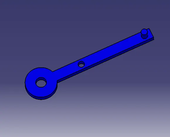
3.Body
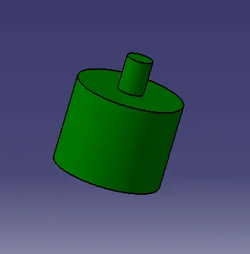
4.Body
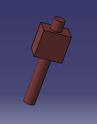
5.Body
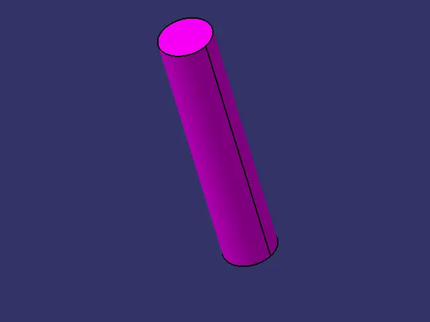
the shaft command is used to create the body of the quick return mechanism.
All the parts of the quick return mechanisam are created succesfully.
ASSEMBLY OF QUICK RETURN MECHANISM:
Assembly modeling is the process of creating designs that consist of two or more components assembled together at their respective work positions. The components are brought together and assembled in Assembly Design workbench by applying suitable parametric assembly constraints to them.
Bottom-Up assembly modeling
Component parts and subassemblies are defined as the process moves up towards the top-level assembly. With this approach, as the design of a key component is completed, its geometry may or may not be used to aid the design of related mating components.
Top- level assembly
Top level assembly is assembly that is not included/assembled in other assemblies but includes subassemblies and parts.
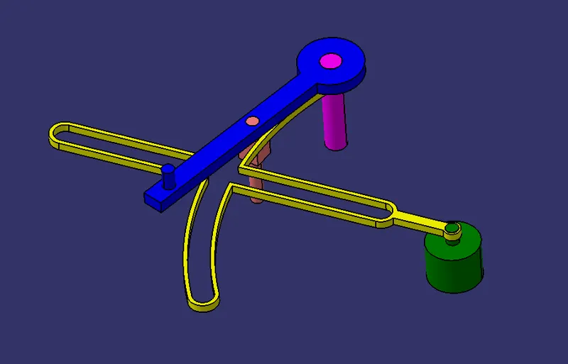
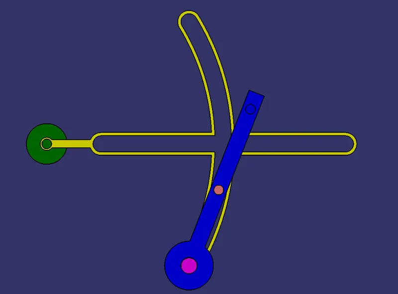
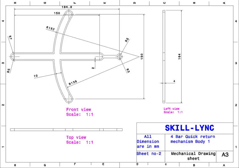
Drawing details of part 1
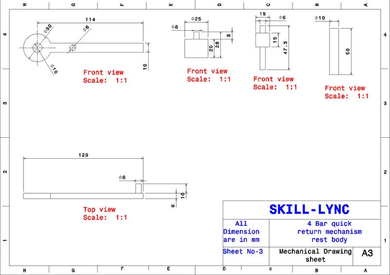
Drawing details of rest parts
2. CV JOINT:
Creation of CV JOINT
First we have to create the all parts and then assemble it.
Constant velocity joints, better known as CV joints, are found at the ends of the drive shafts. They are essential to connecting the drive shafts to the transmission and wheels. Because of their function and location, these joints easily wear out over time. They can even break. To ensure that you understand the importance of them, it helps to know a little more about what they do and what happens when something goes wrong with them. There are two types of CV Joints. The Cardinal, which is usually found in heavy trucks and four-wheel drive vehicles and rzeppa CV joints found on most front wheel drive vehicles.
PARTS OF CV JOINT:
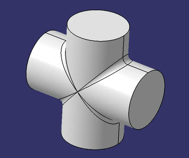
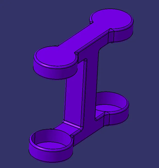
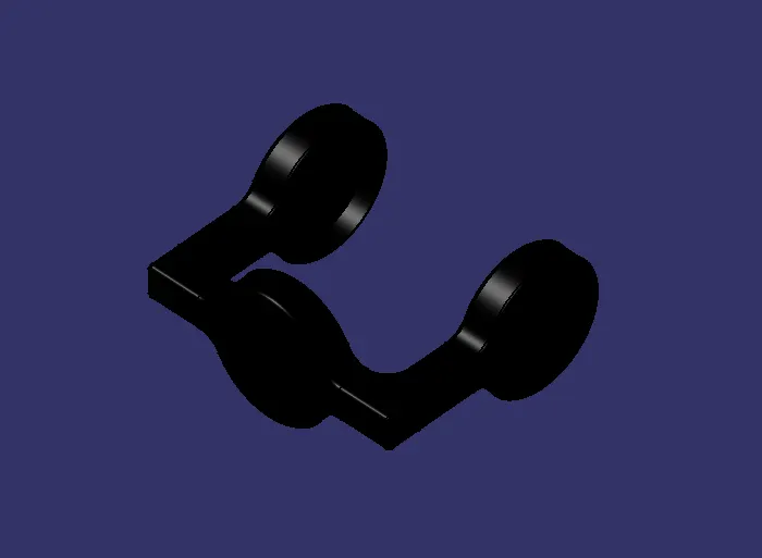
There are 3 parts are there in cv joint
1.body
2.Body
3.Body
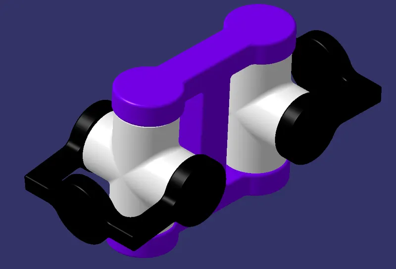
ASSEMBLY OF CV JOINTS:
Drawing details of Assembly
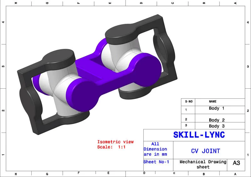
Drawing details of part 1

Drawing details of Part 2
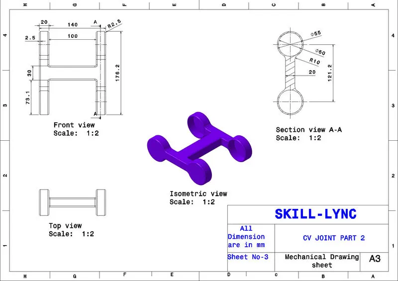
Drawing Details of part 3
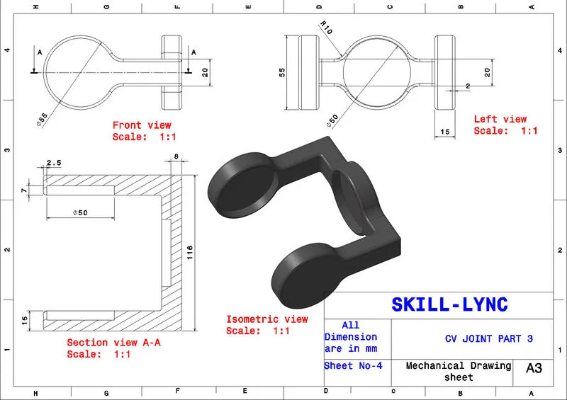
RESULTS:
The assembly of quick return mechanism and cv joint are successfully done by catia assembly workbench.