Week 10- Assembly Workbench
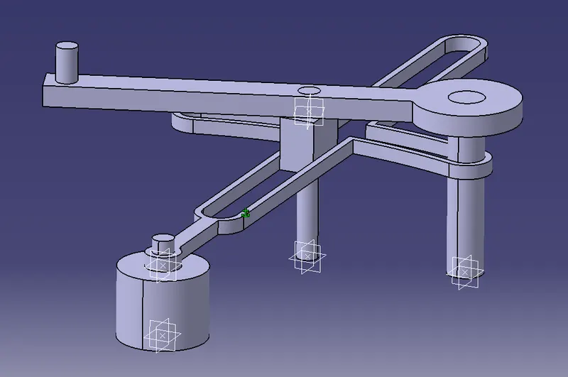
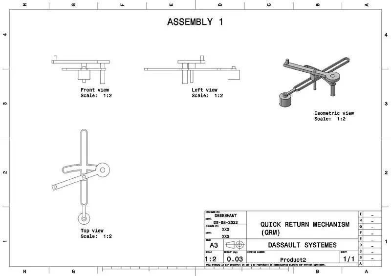
ASSEMBLY 1- QUICK RETURN MECHANISM:
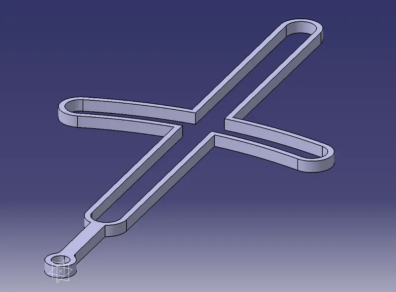
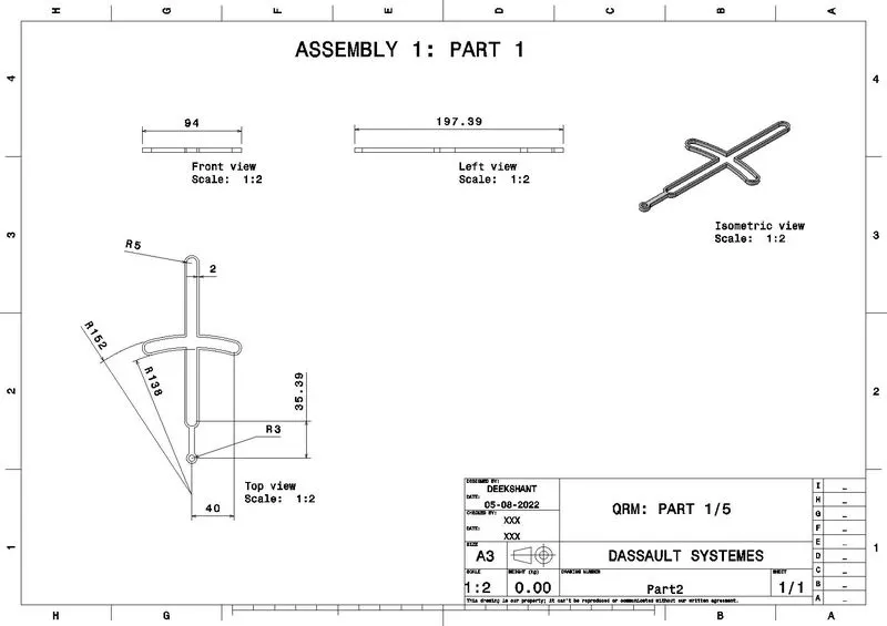
The quick return mechanism assembly consists of 5 parts, these parts are created in seperate .CATPart files. The parts have simple geometry, so the sketches are made and padded to give partbodies.
Part 1
Part 2
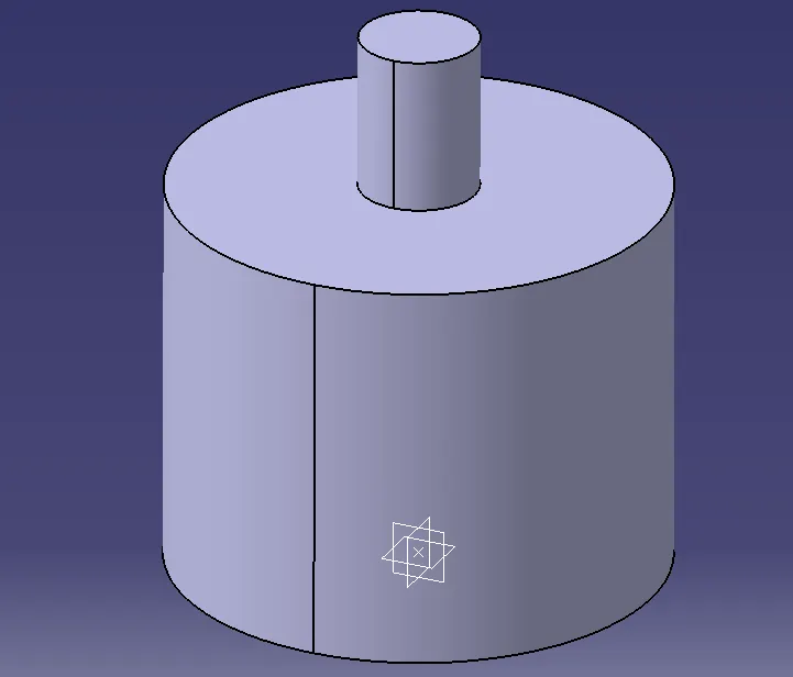
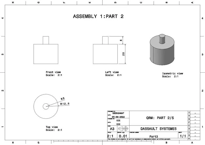
Part 3
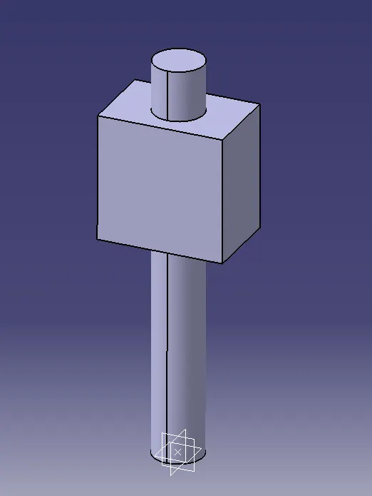
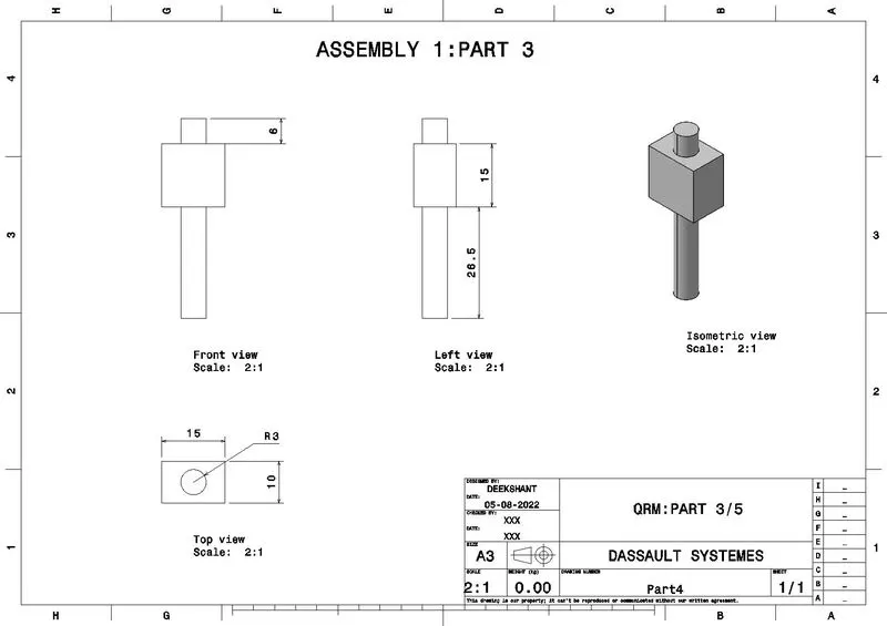
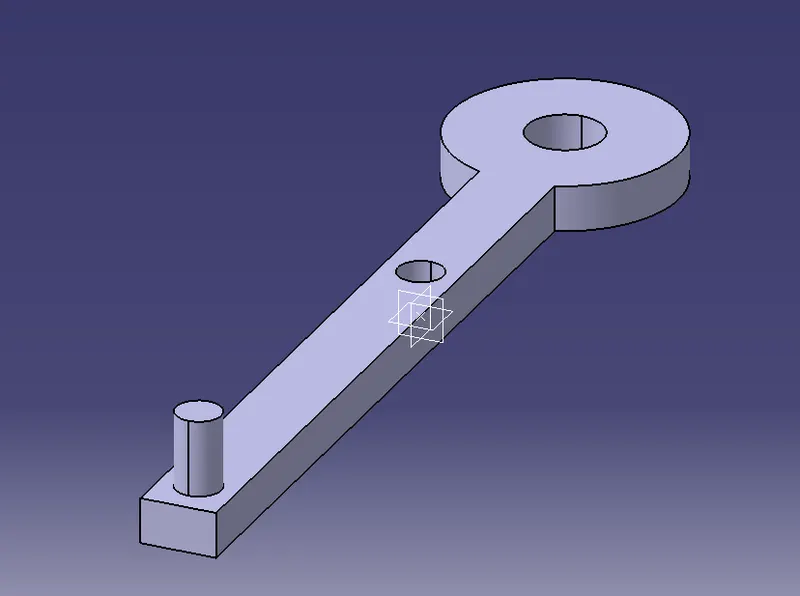
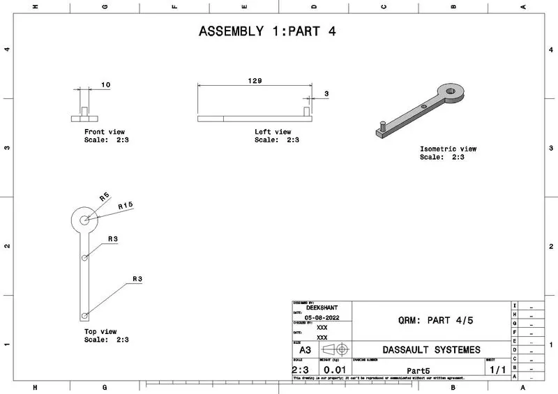
Part 4
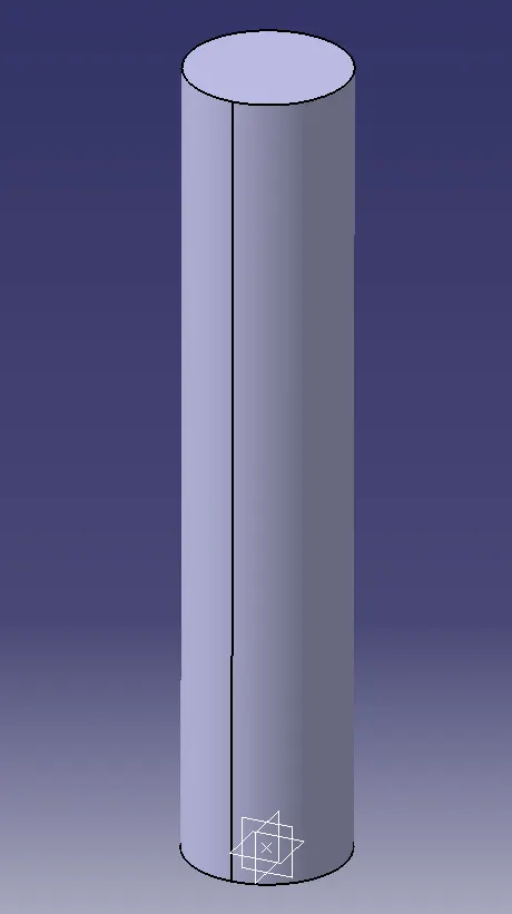
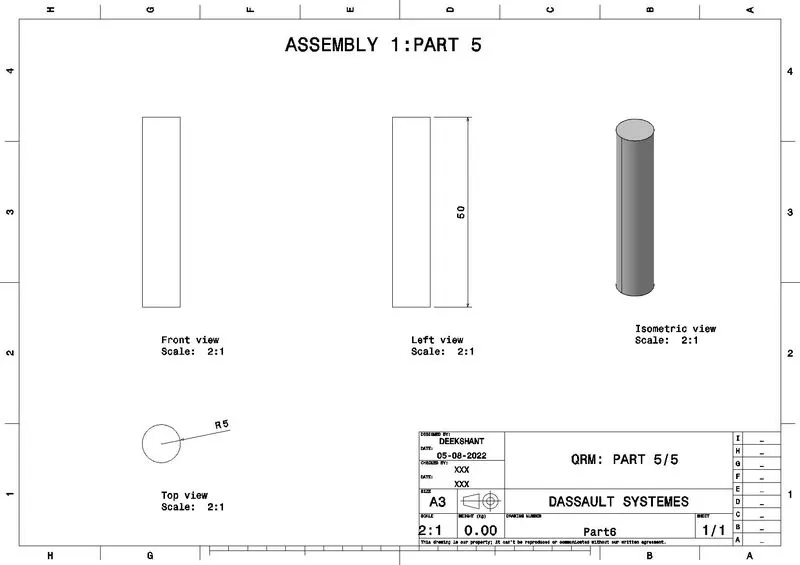
Part 5
Assembly
Parts are assembled in the assembly workbench using the existing part command. For assembling the parts as required, first a part is fixed so that is becomes easier to provide all constraints and relations with reference to that part.
1. Part 1 and Part 2 are assembled with coincidence axis and offset command.
2. Part 1 and Part 3 are assembled using coincidence plane and offset command.
3. Part 3 and Part 4 are assembled using the coincidence axis and offset command.
4. Part 1 and Part 5 are assembled using the coincidence axis and offset command.
5. Part 4 and Part 5 are attempted to assemble but an error pops up. To assemble them, an offset constraint regarding Part 1 and Part 3 is deleted and then Part 4 and Part 5 are assembled using coincidence axis and offset command.
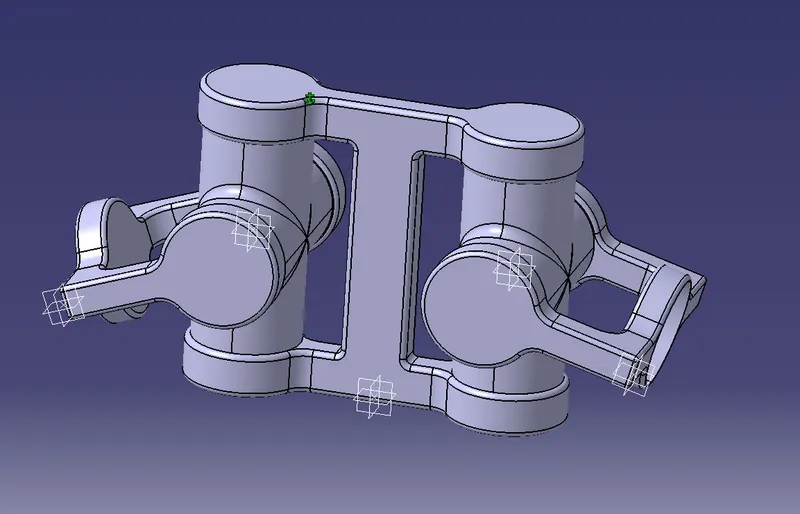
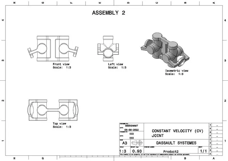
ASSEMBLY 2- CONSTANT VELOCITY JOINT:
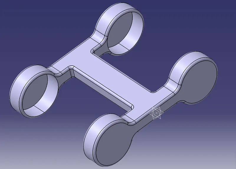
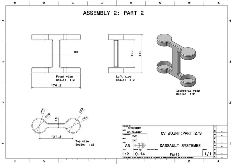
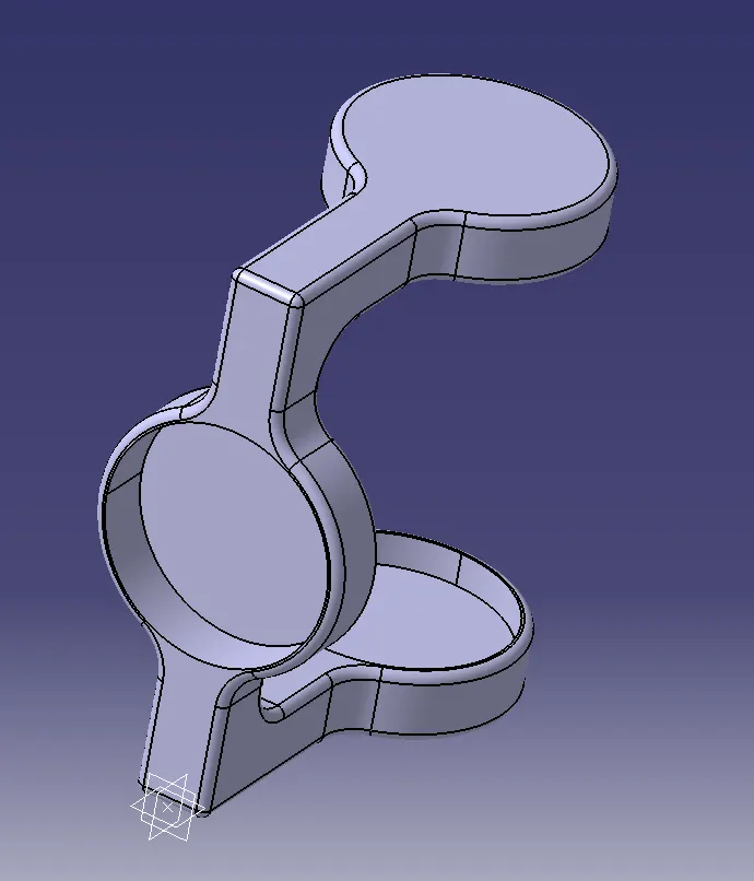
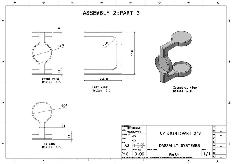
The constant velocity joint has 3 different parts. Out of these three, two parts are repeated which gives the quantity of 5 parts. These parts are made by padding sketches in different planes to make partbodies.
Part 1
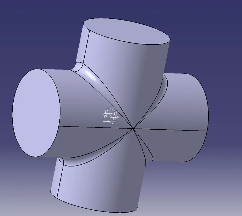
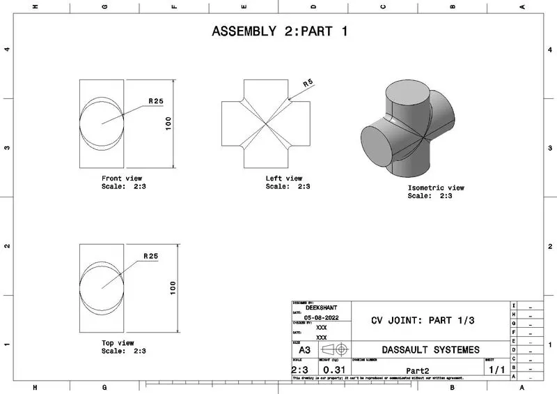
Part 2
Part 3
Assembly
Using the existing part command, all parts are assembled in the assembly workbench. The assembly consists of two quantitles of Part 1 and Part 3, therefore, they are duplicated by copy and paste. Now for the assembly, Part 2 is fixed and other parts are given relations with respect to it.
1. Both instances of Part 1 are assembled to Part 2 with coincidence axis with respective sides of Part 2, and then offsetted from the bottom plane of Part 2.
2. Now one instance of Part 3 is assembled to one instance of Part 1 using coincidence axis and offset command.
3. The other instance of Part 3 is assembled in the same manner with the other instance of Part 1.
After the completion of assembly steps, both isntances of Part 3 are rotated with the help of compass to give a better view of the assembly.