Week 10- Assembly Workbench
ASSEMBLY WORKBENCH
The assembly workbench is the final workbench in the plastic product design. This workbench is used to assemble/align two or more bodies which helps us to get the visual representation of the designed product, that how it may look after the manufacturing process.
So here in this task we have been given the two product that is to be designed part by part and then finally the assembly work is to be done as shown in the figure below.
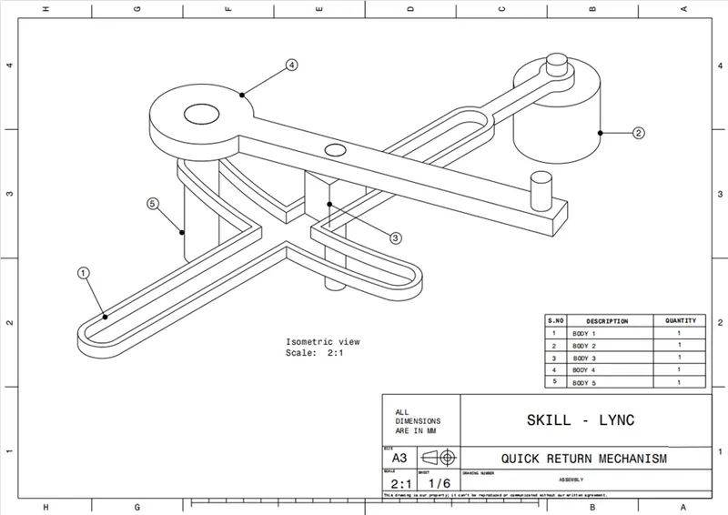
Fig no.1
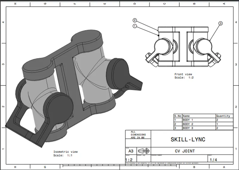
Fig no. 2
The above given figures are the component that are to be designed part by part and then it is finally assembled.
So now initially let’s start with the quick motion mechanism figure no. 1. Here firstly the base of the mechanism is sketched and then it is extruded as this part is made using the surface workbench, then the body was inserted and then this part was turned into the solid body as shown in the figure below.
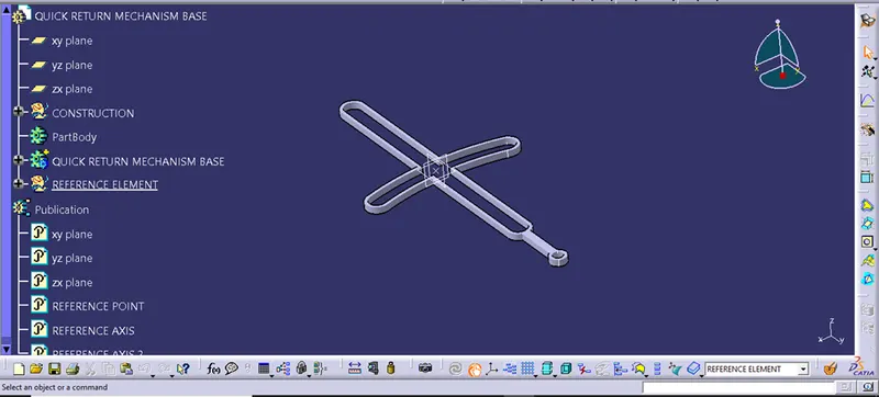
Similarly the next part as shown in the given figure below is designed.
The designed part is given below :-
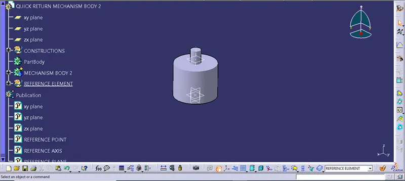
The next part that is to be designed is given as follows.
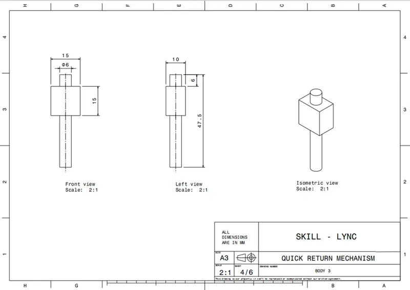
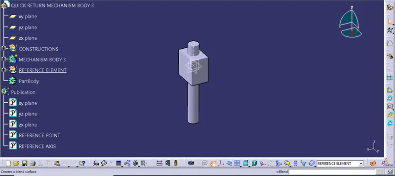
The above given part is designed using the part workbench as shown in the figure above.
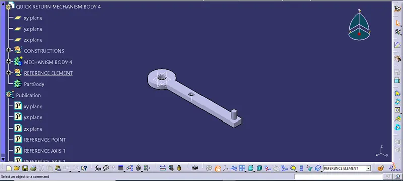
The next part that is to be designed is given as follows:-
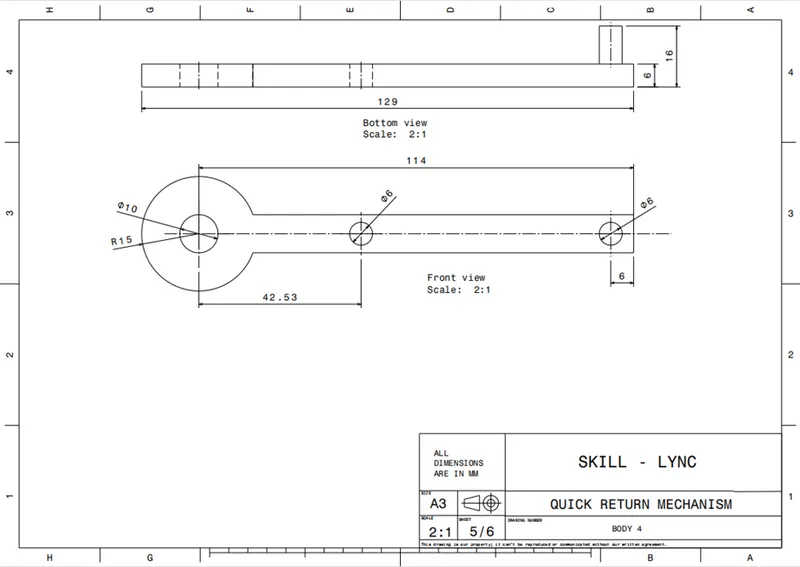
The above given part is designed using the part workbench as shown below.
The last and the final part that is to be designed is the shaft given below:-
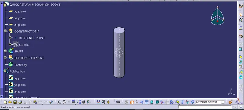
So now all the parts given in the figure no. 1 is designed carefully now the final task is remain that is the assembly. So now all the parts are opened and are copied in the assembly workbench one by one and then the reference elements are given to the each part the axis and the point are published in all the parts one by one. So that in future if any changes happens in figure so that will not damage the constraints given using the published references.
In assembly work bench what is done is all the moments of the freedom are blocked by giving constraints to the published references as shown in the below assembled figure.
Given below is the assembled structure of the component as the input :-
Now the structure which we have assemble is given below with the proper constraints.
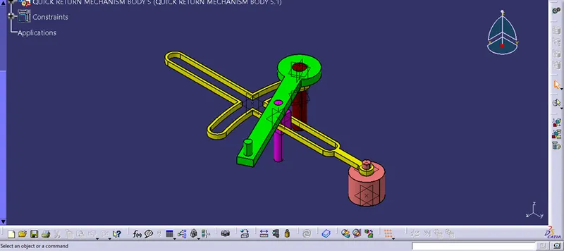
The images of the constraints given to the parts is also given below.
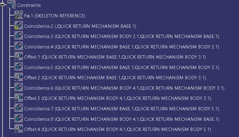
So here we complete the assembly of the first component.
Now let’s start the design of the next component as shown in the figure below.
Now initially here the circular cross design is sketched and then is pad using the part workbench as shown in the figure below.
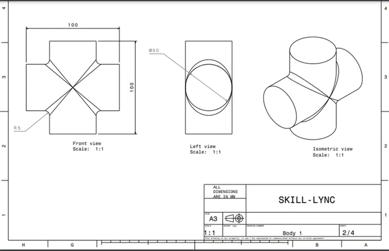
The above given figure is the input given.
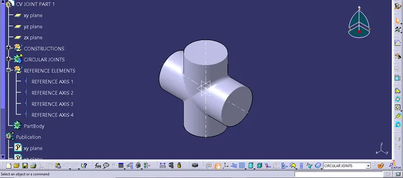
The designed part.
The next part that is to be designed is given below:-
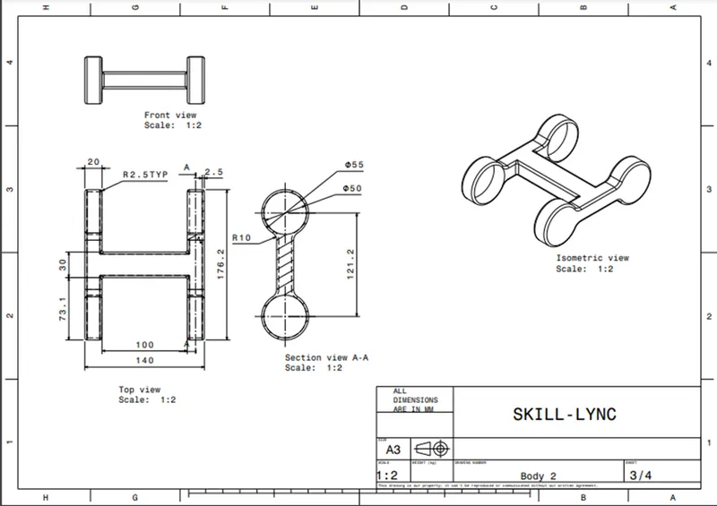
This part is also designed using the part workbench here one side of the component is made and the second one is mirrored as shown in the figure below.
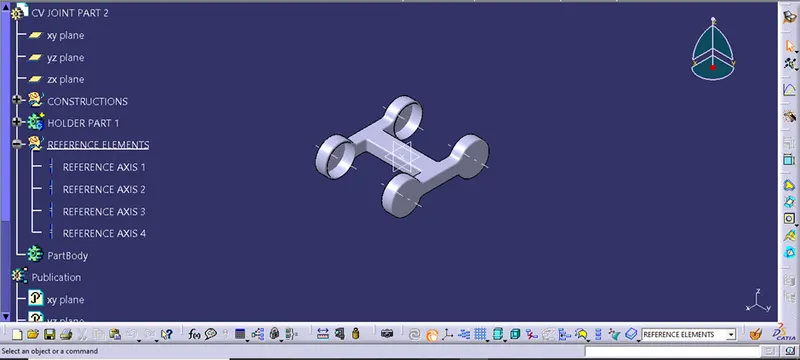
So now the next component that is to be designed is the given as an input in the below figure:-
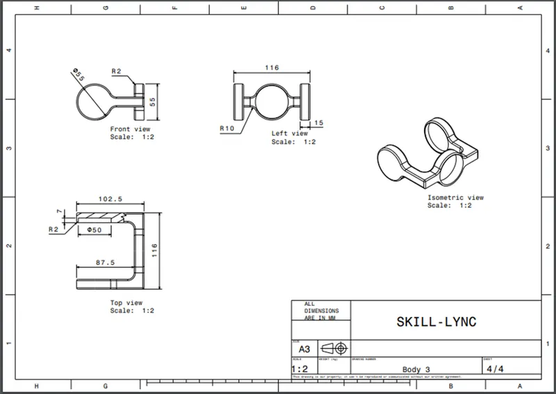
This part is also designed in the part workbench as shown in the below figure:-
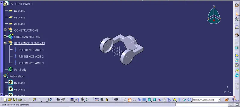
So now all the given parts in the figure no. 2 is designed carefully using the Boolean operations. And now the assembly work is to be done. So similarly as the previous one all the parts are copied and paste into the assembly workbench. Then the reference elements and the reference points are published and finally they are given the constraints as per the required assembly.
Given below is the assembly of the component as an input :-
The actual assembly is shown in the figure below along with the constraints provided to it.
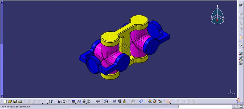
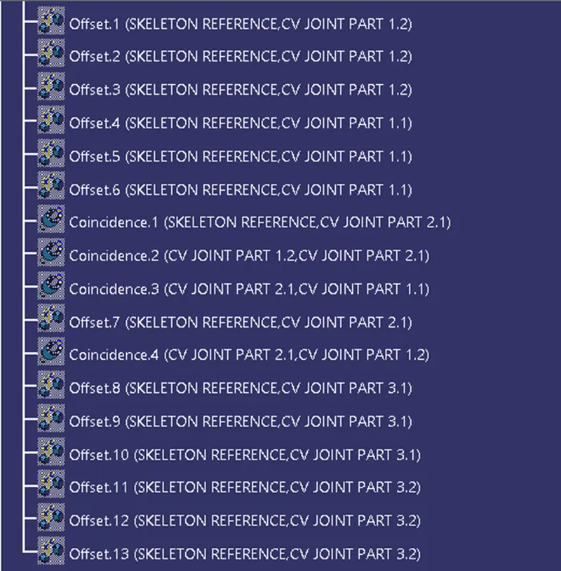
So hence here our design and the assembly of both the components is completed.
DRAFTING OF THE COMPONENTS :-
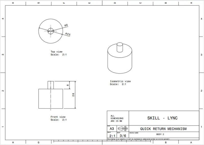
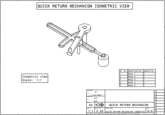
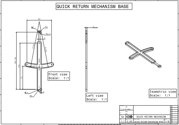
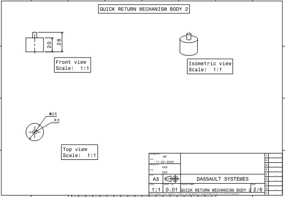
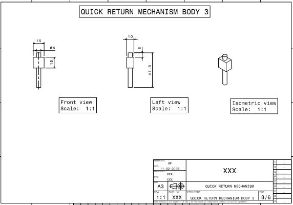
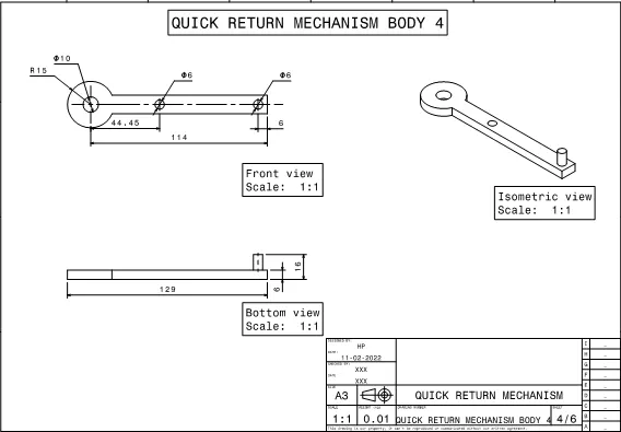
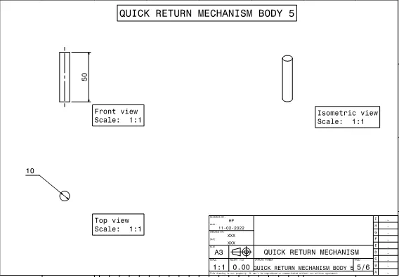
- Quick motion mechanism:- The below given drafting is of the first component named quick return motion mechanism.
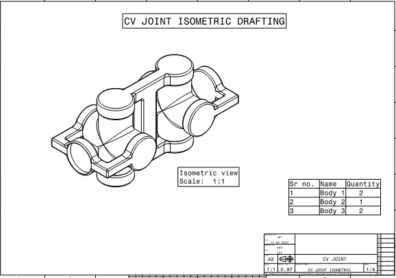
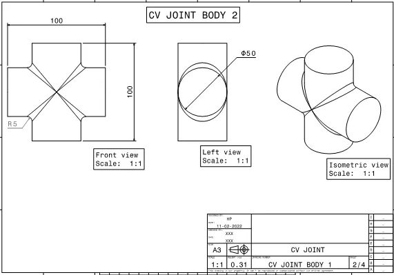
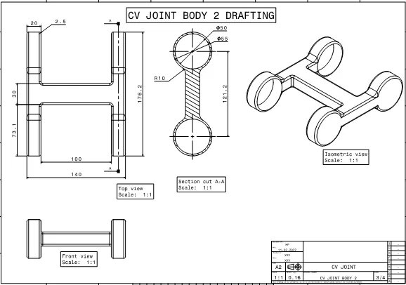
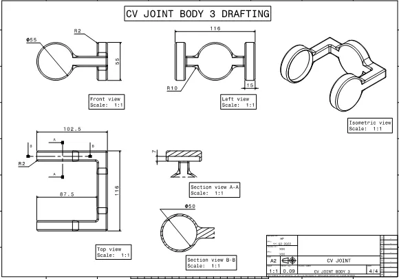
- CV Joint :- The given below drafting is of the second component named the CV Joint.
Hence our assembly workbench is fully completed.