Week 1 Stress Concentration on a Plate with hole
AIM:
Determine the stress Concentration on a plate by conducting structural analysis using ANSYS WORKBENCH.
OBJECTIVE:
Create two Designs of plate in ANSYS Space Claim and specify Fixed supports, Force loads and proper mesh on the geometry in Mechanical Moduler get the Results of Total deformation and Equivalent stress to find stress concentration in the model. Finally compare the results and prefer which design is best from CAE Engineer point of view and Manufacturer point of view.
PLATE DESIGN PARAMETERS:
CASE-1
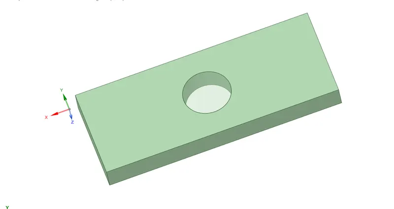
Length=300mm
Height=120mm
Thickness=30mm
Circular Hole at the center:
Diameter=60mm
CASE-2
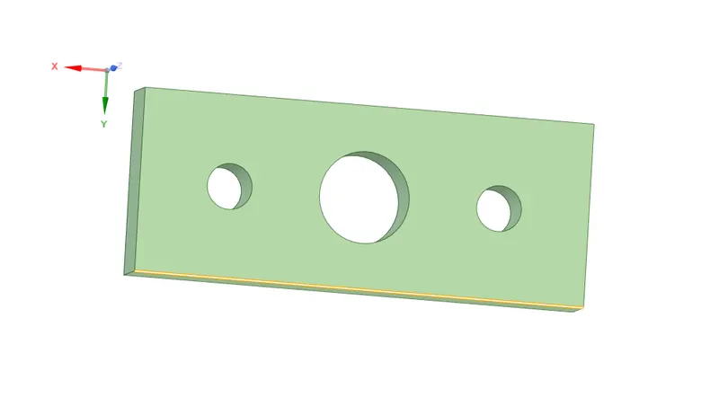
Length=300mm
Height=120mm
Thickness=30mm
Circular Hole at the center:
Diameter=60mm.
Smaller holes 90 mm away from centre
Diameter =30 mm.
BOUNDARY CONDITIONS:
Plate is fixed at left face
Load of 500N is applied at right face.
PROCEDURE FOR DESIGN PLATE:
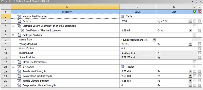
*Assign the material as structural steel for both the cases by, Selecting the Engineering data >> Edit >> Engineering data sources >> General Materials >> Structural steel.
*Properties of the structural steel is shown in below Fig(1).
Fig(1).
*After Assigning the material close the engineering data and open new space claim to make the required designs.
DESIGN FOR CASE-1
Fig(2).
DESIGN FOR CASE-2
Fig(3).
PROCEDURE FOR STRUCTURAL ANALYSIS:
*Once geometry is imported from the space claim then open the model and eidt the geometry in Mechanical moduler.
*Create the mesh on the geometry with element size is 4 mm and type of the mesh is tetrahedron.
*Create the fixed support at the left face of the plate and force load of 500 N is applied at the right face of the plate.
*Insert the Total deformation and equivalent stress from the solution By, Selecting Solution >> Insert >> Deformation or Stress to identify the stress concentration of the plate under Simulation.
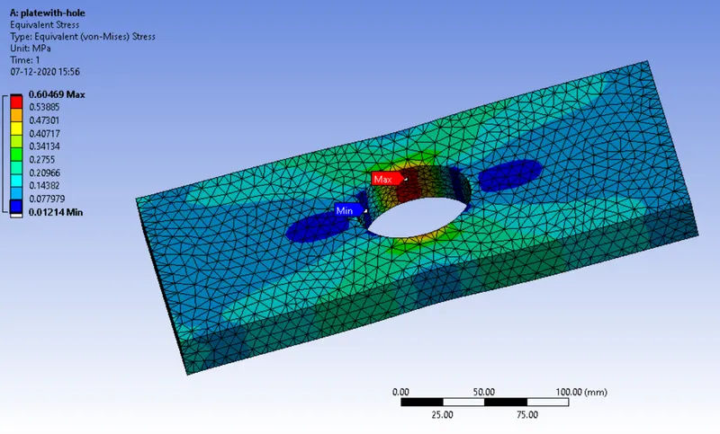
CASE-1
EQUIVALENT STRESS:
Max:0.604 (Mpa) and Min: 0.0121 (Mpa)
Fig(4).
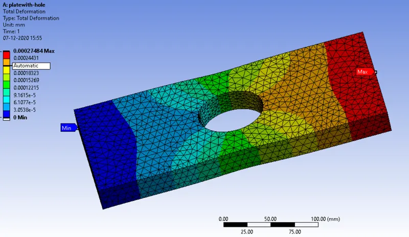
TOTAL DEFORMATION:
Max:0.00027 (mm) Min: 0 (mm).
Fig(5).
CASE-2
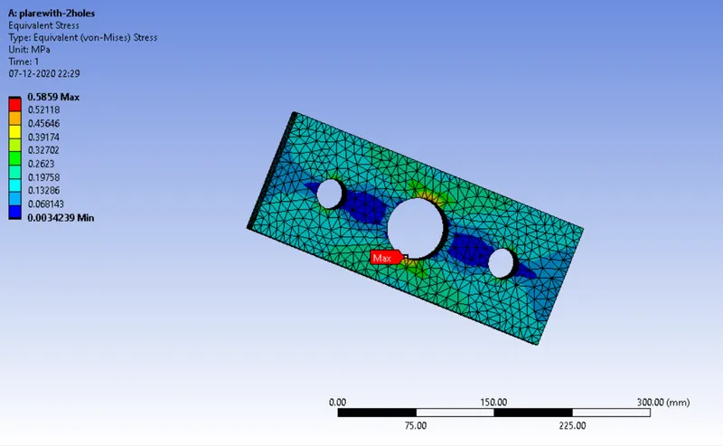
EQUIVALENT STRESS:
Max:0.5859 (Mpa) and Min: 0.00342 (Mpa)
Fig(6).
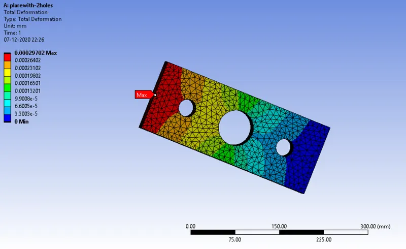
TOTAL DEFORMATION:
Max:0.00029 (mm) Min: 0 (mm).
Fig(7).
COMPARISION:
COMPARISION OF EQUIVALENT STRESS BETWEEN THE TWO CASES :
In case-1 the maximum stress is 0.604 (Mpa) and in case-2 the maximum stress is 0.5859 (Mpa). By comparing the stress values between this two cases, the Maximum stress in case -2 is smaller than the case-1 due to creation of two extra holes near the large hole there is a uniform distribution of stress than case-1.
COMPARISION OF TOTAL DEFORMATION BETWEEN THE TWO CASES :
In case-1 the maximum deformation is 0.00027 (mm) and In case-2 the maximum deformation is 0.00029 (mm). By comparing the deformation values between this two cases, Total deformation in case-2 is more than the case-1 due to uniform distribution of stress in case-2 more than the case-1.
CONCLUSION:
SELECTION OF DESIGN FROM AN ANALYSIS POINT OF VIEW:
*From an anlysis point of view case-2 model should be selected due to uniform stress disstribution than case-1 model.
*Selection of case-2 resulting the weight reduction of material.
SELECTION OF DESIGN FROM A MANUFACTURING POINT OF VIEW:
*From a manufacturing point of view case-1 model should be selected because it is easy to manufacturing the plate with one hole than plate have having three holes.
*It reducess the production time and cost.
*It decreases the material wastage.