Week 1 Stress Concentration on a Plate with hole
AIM:
Case :1
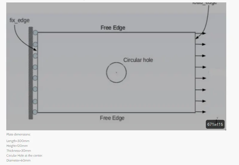
Design a plate with a hole model similar to what we worked in the class, but with increased thickness.
Determine the maximum deformation and stress developed in the model.
Case 2:
Consider you are a Product Engineer in an Automotive industry.
You are assigned the following responsibilities:
- Compare the deformation and maximum stress developed on a structural steel model for the 2 cases.
- From an analysis standpoint, which of the design will you select? Explain why?
- From a manufacturing standpoint, which of the design will you select? Explain why?
- Report writing
Procedure:
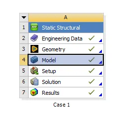
- open the ANSYS workbench>we will get the panel>click on the structual analysis>a dialogue box of geomentry>model>mesh>solve>will be appear.
- we should have to go geomentry>clcik on edit geomentry in space claim> and space window will be appeared.
- we should have to draw the model in the Space GUI.
- We should have to create a rectange of length=300mm and height=120mm and having a circle diamter of 60.
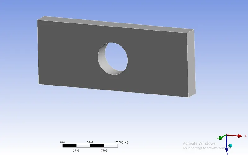
- After creating the Rectangle plate with the circle we should have give the thickness to the model.
- we should have to give thickness pull by 30mm and we get the model as shown in the below.
- After the geomentry space claim we should have to close the tab and we should go to model tab and click open the tab.
- we can see the model that is imported from the geomentry and we should have to work on the model.
- we can delete the unused cintact surface in the model.
- we should have to give the mesh paramter to the model.
- We should go to mesh>element size as 5 as the small element size it was not excetive in the student version so we have assigned 5mm as the target element size and we should right click on the mesh and select the type aas tetra herdal mesh clcik on generate mesh.
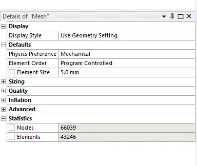
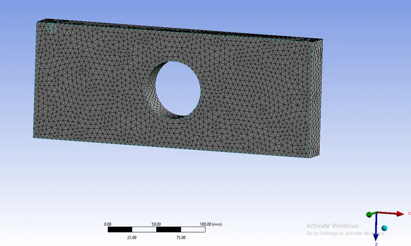
- Hence the mesh is generated.
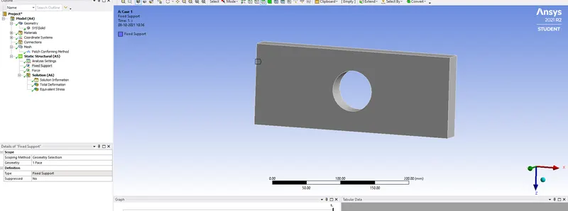
- After creating the mesh we should have to go to the static structural and we should have to create the fixed support on the left hand.
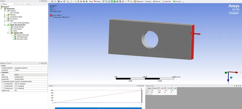
- And we should have to give the force as 500N on the x-axis and select the component and we should have give the force on the free edge of the surface.
- we should have to solve the static structure of the model.
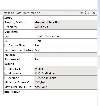
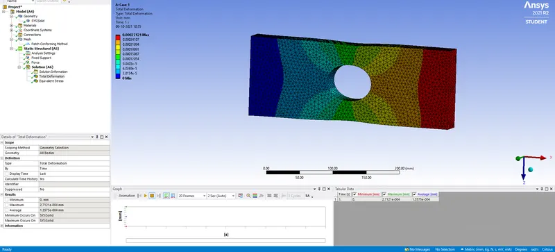
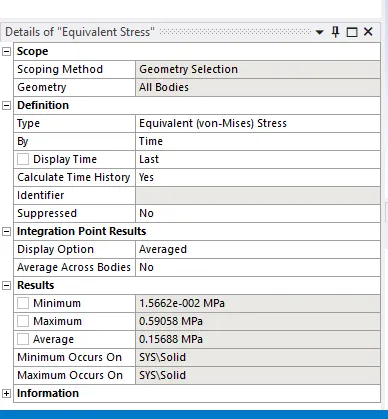
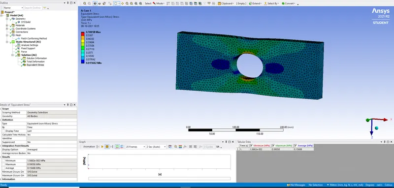
- we should have go to the solution and give the Total deformatiom and stress of the given model.
- And we should have tp evulate the results and we can see the Toatl deformation and stress of the given component.
Case 2:
- open the ANSYS workbench>we will get the panel>click on the structual analysis>a dialogue box of geomentry>model>mesh>solve>will be appear.
- we should have to go geomentry>clcik on edit geomentry in space claim> and space window will be appeared.
- we should have to draw the model in the Space GUI.
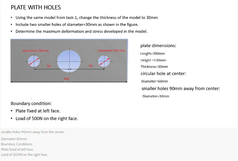
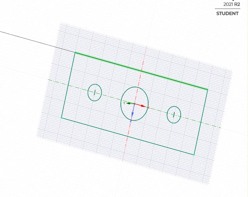
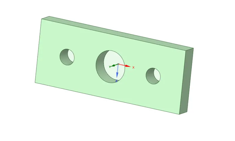
- We should have to create a rectange of length=300mm and height=120mm and having a circle diamter of 60.And we should have to create two holes on left and right side of the centre hole with the diameter of 30 and having the distnace from the centre of 90mm.
- After creating the Rectangle plate with the circle we should have give the thickness to the model.
- we should have to give thickness pull by 30mm and we get the model as shown in the below.
- After the geomentry space claim we should have to close the tab and we should go to model tab and click open the tab.
- we can see the model that is imported from the geomentry and we should have to work on the model.
- we can delete the unused cintact surface in the model.
- we should have to give the mesh paramter to the model.
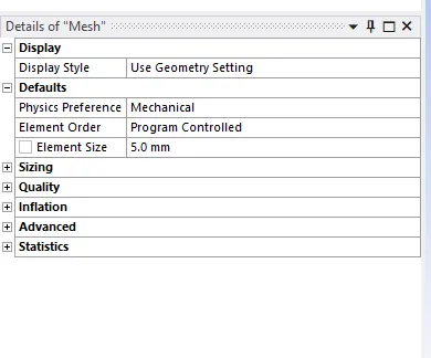
- We should go to mesh>element size as 5 as the small element size it was not excetive in the student version so we have assigned 5mm as the target element size and we should right click on the mesh and select the type aas tetra herdal mesh clcik on generate mesh.
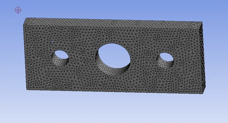
- After creating the mesh we should have to go to the static structural and we should have to create the fixed support on the left hand.
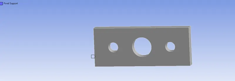
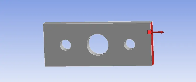
- And we should have to give the force as 500N on the x-axis and select the component and we should have give the force on the free edge of the surface.
- we should have to solve the static structure of the model.
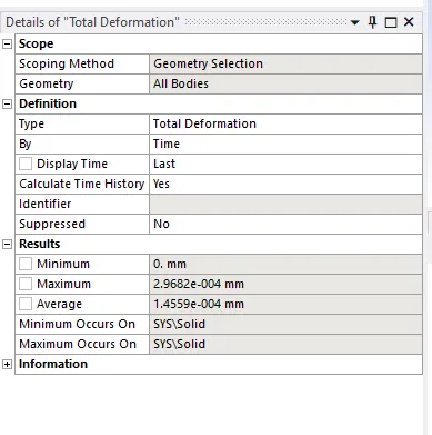
- we should have go to the solution and give the Total deformatiom and stress of the given model.
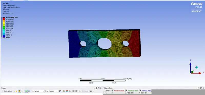
- And we should have tp evulate the results and we can see the Toatl deformation and stress of the given component.
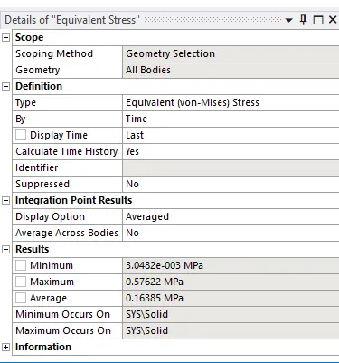
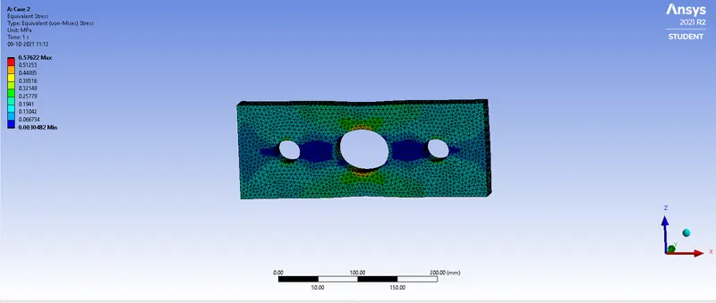
From the above two case the deformation and stress in the both plates are
- Case 1 Deformation(Max)=2.71216-004(mm)
- Case 1 Stress(max):0.59058 MPa
For the case 2:
- Deformation: (Maximum)=2.9682e-004(mm)
- Stress(Max)=0.57622 MPa
As from the above cases 1 and 2 we have seen the deformation fpr plate 1 with one hole have less deformed with respective to the plate having 3 holes.
Stress formation we have seen that stress maximum is more in plate 1 compared to plate 2.
From the analysi point of view plate 2 is selected because the stress conceration is less compared to plate 1.
From the manufacture point of view plate 1 is slecetd because it undergoes less deformation compared to plate 2 so that its better during the machining process
Hence the Report of the model is done on the Ansys workbench 2021.