Stress Concentration on a Plate with hole
AIM:
- To design a Structural Steel plate with a hole and to evaluate the maximum stress and deformation.
OBJECTIVES OF THE PROJECT:
- To create a plate with a hole.
- To apply the boundary conditions for the plate.
- To apply tensile force of 500N to the plate.
- To mesh the plate with appropriate mesh size.
- To evaluate the stress and deformation in the plate.
- To compare between the two case setup.
PROCEDURE:
- Case 1: Plate with one hole.
- OPEN WORKBENCH21 > NEW PROJECT > STATIC STRUCTURAL.
- This will start a new static structural project.
- Rename the project as Case_1_Plate_with_hole.
- Then double click on Geometry. This will open the Spaceclaim.
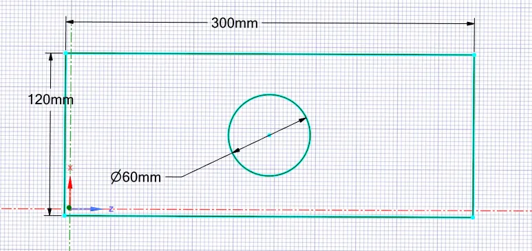
- In Space claim create RECTANGLE with the following dimensions –
Length = 300mm
Height = 120mm
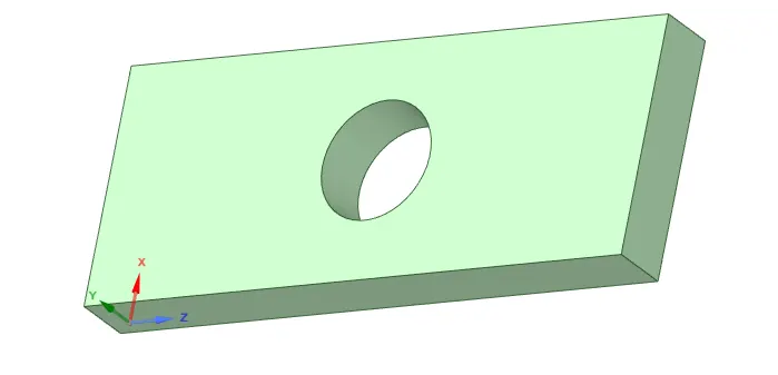
Thickness = 30mm
Circle diameter = 60mm at the center
-
- Now, select PULL option and increase the thickness to 30mm.
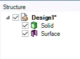
- Then DELETE the surface.
- The geometry for the case is done and exit the Spaceclaim.
- Then double click on Model. This will open Mechanical module.
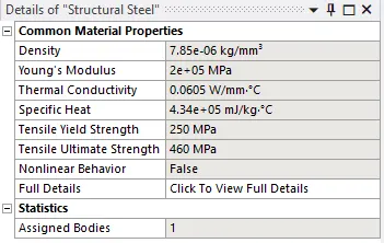
- Then go to MATERIALS > STRUCTURAL STEEL.
- The Structural steel material is defined for the model having the following properties-
- Now, go to MESH > RIGHT CLICK > INSERT > METHOD > TETRAHEDRON.
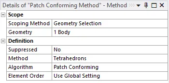
- This will define Tetra meshing on the model.
- Now, go to MESH > ELEMENT SIZE = 2MM > GENERATE MESH.
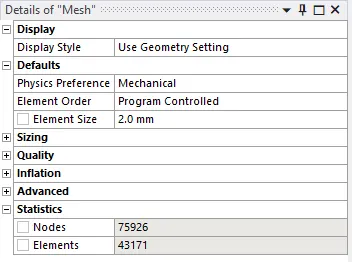
- The mesh will be generated on the model.
- Then go to STATIC STRUCTURAL > INSERT > FIXED SUPPORT > GEOMETRY FACE > TYPE = FIXED.
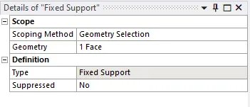
- This will fix one end of the plate.
- Go to STATIC STRUCTURAL > INSERT > FORCE > GEOMETRY FACE > DEFINED BY COMPONENTS > Z COMPONENT = 500N.
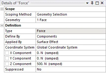
- This will apply tensile force on the other face of the plate.
- Then, go to SOLUTION > INSERT > MAXIMUM STRESS > TOTAL DEFORMATION.
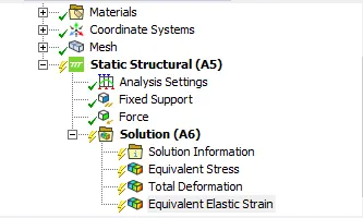
- This will provide the output results for the plate.
- RIGHT CLICK ON SOLUTION > SOLVE.
- The ANSYS Workbench will solve the problem according to the boundary conditions proivded and evaluate the results at the nodes and in the element using the shape functions.
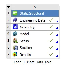
- The tick mark shows the project is completed.
- Case 2: Plate with three holes.
- OPEN WORKBENCH21 > NEW PROJECT > STATIC STRUCTURAL.
- This will start a new static structural project.
- Rename the project as Case_1_Plate_with_hole
- Then double click on Geometry. This will open the Spaceclaim.
- In Space claim create RECTANGLE with the following dimensions –
Length = 300mm
Height = 120mm
Thickness = 30mm
Circle diameter = 60mm at the center
Circle diameter = 30mm each at 90mm from the bigger circle.
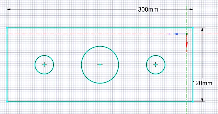
- Now, select PULL option and increase the thickness to 30mm.
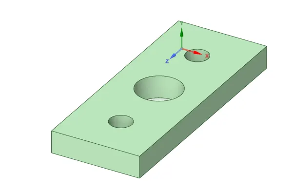
- Then DELETE the surface.
- The geometry for the case is done and exit the Spaceclaim.
- Then double click on Model. This will open Mechanical module.
- Then go to MATERIALS > STRUCTURAL STEEL.
- The Structural steel material is defined for the model having the following properties-
- Now, go to MESH > RIGHT CLICK > INSERT > METHOD > TETRAHEDRON.
- This will define Tetra meshing on the model.
- Now, go to MESH > ELEMENT SIZE = 4MM > GENERATE MESH.
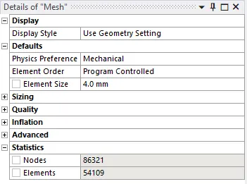
- The mesh will be generated on the model.
- Then go to STATIC STRUCTURAL > INSERT > FIXED SUPPORT > GEOMETRY FACE > TYPE = FIXED.
- This will fix one end of the plate.
- Go to STATIC STRUCTURAL > INSERT > FORCE > GEOMETRY FACE > DEFINED BY COMPONENTS > Z COMP = 500N.
- This will apply tensile force on the other face of the plate.
- Then, go to SOLUTION > INSERT > MAXIMUM STRESS > TOTAL DEFORMATION.
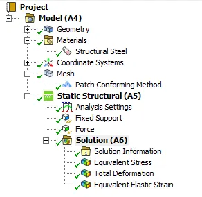
- This will provide the output results for the plate.
- RIGHT CLICK ON SOLUTION > SOLVE.
- The ANSYS Workbench will solve the problem according to the boundary conditions proivded and evaluate the results at the nodes and in the element using the shape functions.
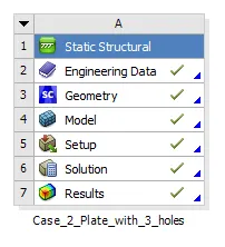
- The tick mark shows the project is completed.
RESULTS:
- Case 1
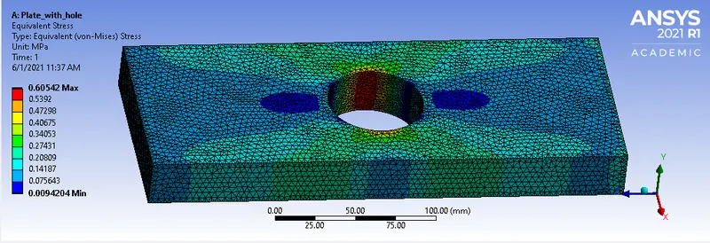
- The stress is developed at the inner edge of the circle. This is due to the change in cross section which develops the stress concentration.
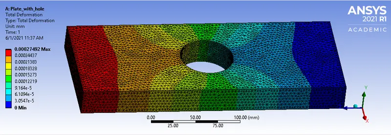
- The deformation of the plate is seen due to the pulling force applied at one end. We can obtain deformation results at any section of the plate throughout the length.
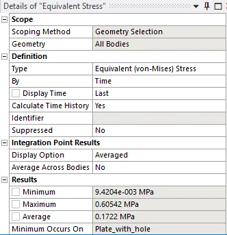
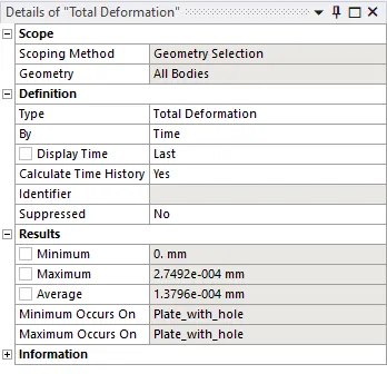
- Hence, for the first case the maximum stress developed is 0.60542Mpa and maximum deformation occured is 0.00027492mm.
- Case 2
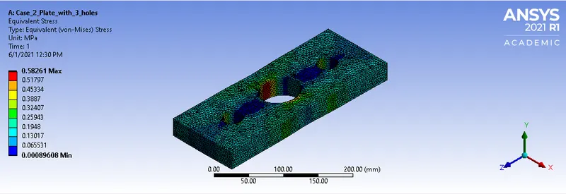
- In comparision to the first case the stress occured in this case is more throughout the plate area. This is due to there are additional holes created adjacent to the bigger hole, resulting in stress concentration.
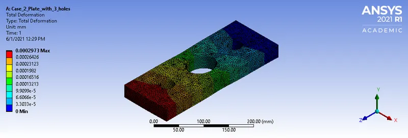
- The deformation of the plate at the free end is more with respect to the fist case. This means, as the cross section is reduced the plate offers less resistance to deformation with the same material properties.
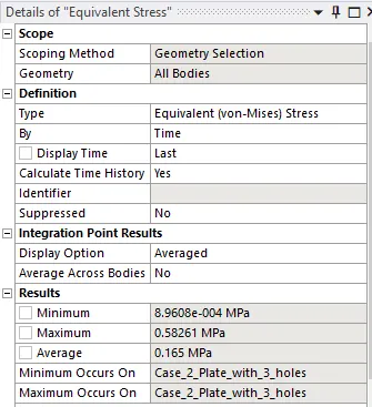
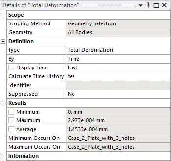
- Hence, for the second case, the maximum stress developed is 0.58261Mpa and total deformation occured is 0.0002973mm.
RESULT EVALUATION:
|
Stress (Mpa) |
Displacement (mm) |
Strain |
|
|
Case 1 |
0.60542 |
0.00027492 |
3.0272e-6 |
|
Case 2 |
0.58261 |
0.0002973 |
2.9131e-6 |
- Stress concentration can be measured by the stress concentration factor "K".
- K is independent of the material properties, rather it only depends on the geometry and the size of discontinuity.
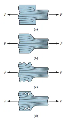
- Fig (a) produces a stress concentration factor greater than 3. In other words, the maximum normal stress will be three times greater than the average normal stress on the smallest cross section.
- This can be reduced to 1.5 by introducing a fillet as in fig (b).
- A further reduction can be made by means of small groves or holes placed at the transition as in fig (c) and (d).
- Hence, providing holes near the big hole reduces the stress concentration.
- Therefore, from the analysis standpoint we will use the second case design.
- But from a manufacturer standpoint, we will choose the first case as it is easy to produce one hole with simple drilll machine and requires less time than producing three holes.
LEARNING OUTCOMES:
- The user interface of ANSYS WORKBENCH.
- To create Geometry in Spaceclaim.
- To define material from the material library.
- To define Boundary conditions in Mechanical module.
- To deploy mesh on the geometry.
- To define meshing method.
- To define output results.
- The effect of stress concentration in plate with holes.
CONCLUSION:
- By performing this project we conclude that the stress concentration is developed due to change in cross section area. The way to reduce the stress concentration is by adding small holes near the big hole or providing fillets instead of sharp corners.