Week 1 Stress Concentration on a Plate with hole
- Objective: To study and compare the effect of stress concentration on plate with hole for different cases.
- Procedure: Open the Static Structural Analysis system in the Project schematic and rename it to plate_with_hole.
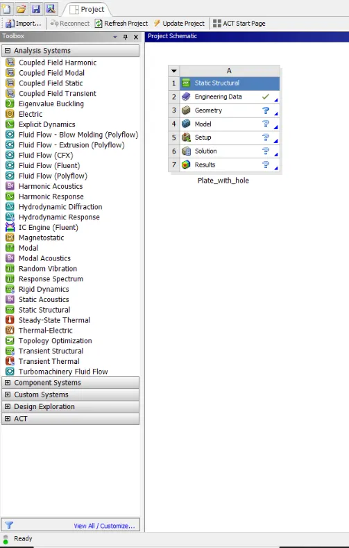
We don’t need need to add any material in the material library in the Engineering Data, since we are going to use Structural steel which is available by default in the material librabry.
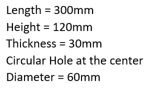
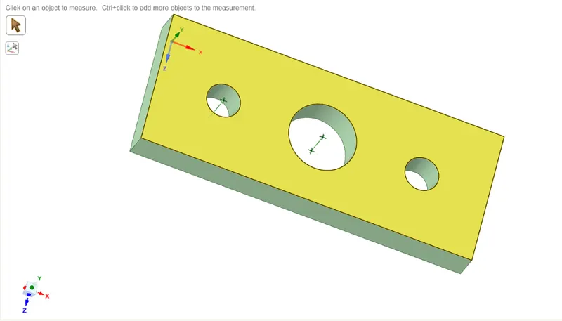
Now we need to create the geometry for Case 1. Geometry is created for Case 1 using SpaceClaim.The dimesions of the plate are as follows:
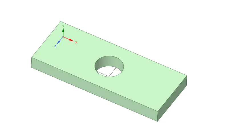
Update the geometry in the mechanical module by right clicking on the Model > Update in the project schematic. The model will be updated, meshed automatically and material
structural steel will be automatically applied to the model. By default, the model is meshed with brick elements. We need to change the elements type to Tetrahedrons with element size
of 2mm. Right click on the mesh in the outline and click on Insert > Method. Select the model in the Geometry selector and set the method to Tetrahedrons.
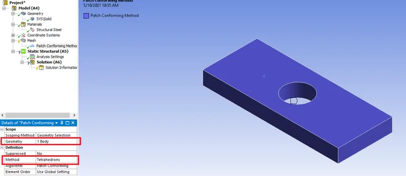
In the mesh outline, click on Mesh > Defaults> element size. Enter element size = 2 mm. Click on Generate mesh. The mesh will be updated. Now we need to apply constrains on the
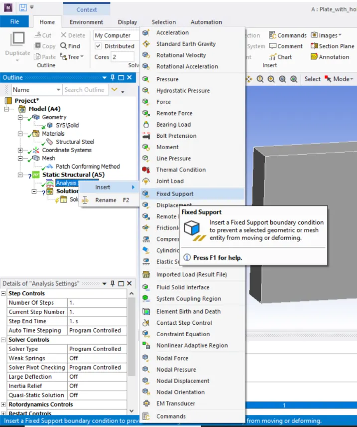
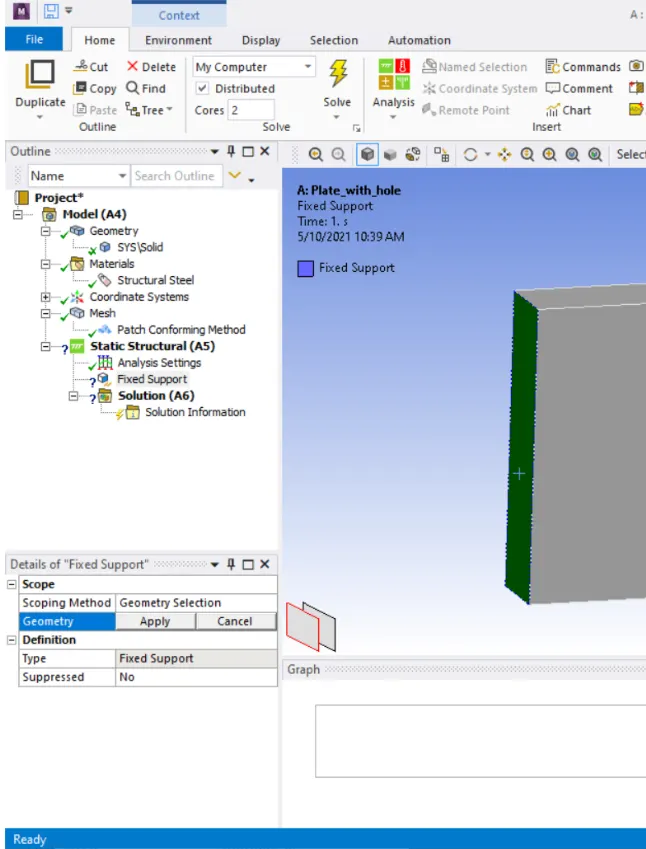
model. Fix the left side of the plate and on the right side apply a tensile force of 500N. To create fixed support, right click on the Analsysis Setttings > Insert > Fixed Support. In the
Geometry selector, select the left side face and click on apply. Fixed support is now created.
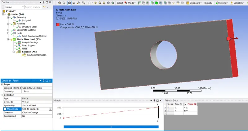
Now apply the force of 500N on the right side of plate. Right click on the Analsysis Setttings > Insert > Force. In the geometry selector, select the right side of the plate. Enter
magnitude of 500N.
Since the constrains are applied, we can run the simulation. But before that, we need to request the output we require, in this case those are stress and deformation. Right click on the
Solution > Insert > Stress > Equivalent Stress for von mises stress.
Solution > Insert > Deformation > Total for total deformation.
Right click on Solution > Solve. The simulation will start running.
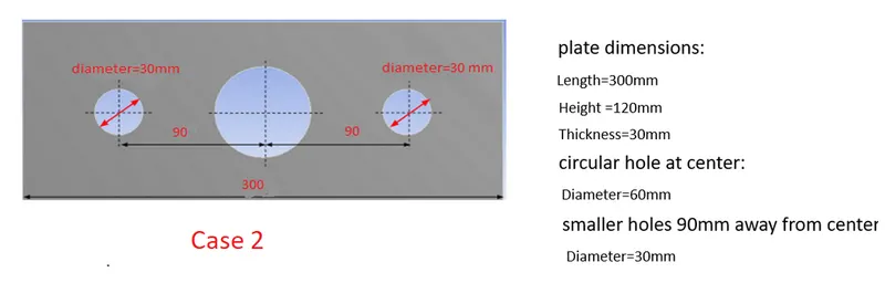
After completion of the simulation, save the model and create the model for case 2 with following dimensions using the same procedure discussed above. Same boundary conditions are
applied to the model. After case setup, run the simulation.
- Results:
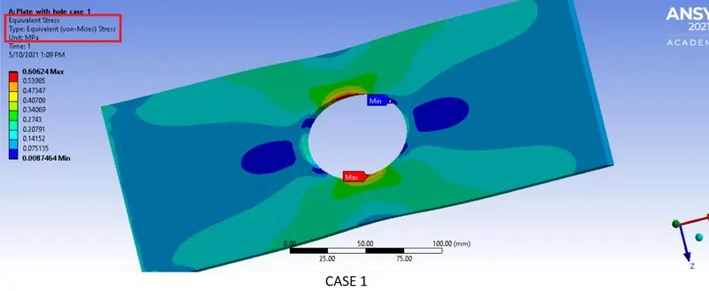
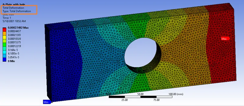
Case 1: Stress and deformation:
Case 2: Stress and deformation:
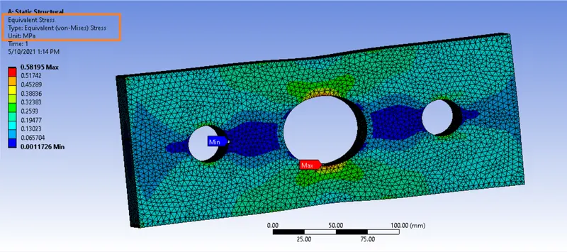
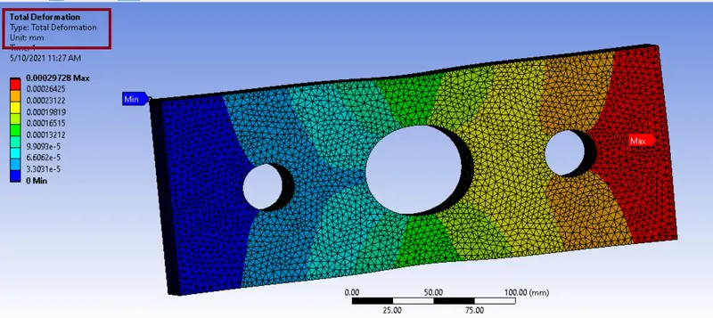

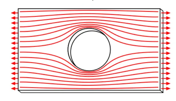
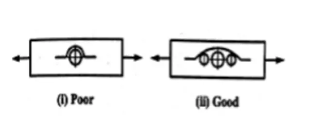
The deformation in Case 2 is more compared to Case 1. This is due to reduction in the material due to drilling of additional holes. The stress is lower in Case 2 design due to the fact that the stress flow
lines are smoother compared to Case 1. This can be understood by referring the below fig.
- Conclusion:
Clearly, from the analysis point of view, Case 2 is an appropriate design compared to Case 1 since the stress induced in Case 2 design is less compared to Case 1. But from manufacturing
point of view, Case 1 is an appropriate design since the difference between the stresses induced in both the designs is negligible and the stresses in both the cases are way lower
compared to the yield strength of the steel. Manufacturing with Case 2 design is not feasible considering the additional loss in manufacturing time and cost due to drilling of
additional holes.