Spur Gear Static Structural Analysis
AIM:
- To perform Static Structural analysis on a spur gear pair using different materials and find the best results in ANSYS Workbench.
OBJECTIVES OF THE PROJECT:
- To define materials for the spur gear pairs.
- To define contact faces for the teeth.
- To define revolute joint for the gears.
- To define the rotation and moment on the gears.
- To perform mesh on the gear pair.
- To evaluate the maximum stress, strain and deformation.
- To define the best results for a material.
STRESS INTENSITY:
- The stress intensity factor K, is used in fracture mechanics to predict the stress state near the tip of a crack or notch caused by a remote load or residual stresses.
- The magnitude of K depends on specimen geometry, the size and location of the crack or notch, and the magnitude and the distribution of loads on the material. It can be written as -
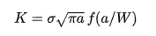
- where, f(a/W) is a specimen geometry dependent function of the crack length a, and the specimen width
 , and
, and  is the applied stress.
PROCEDURE:
- Case 1 :
- OPEN > WORKBENCH > NEW PROJECT > STATIC STRUCTURAL > CASE_1_CAST_IRON.
- This will define static structural project.
- Now, go to ENGINEERING DATA > EDIT > ENGINEERING DATA SOURCES > CAST IRON > ADD.
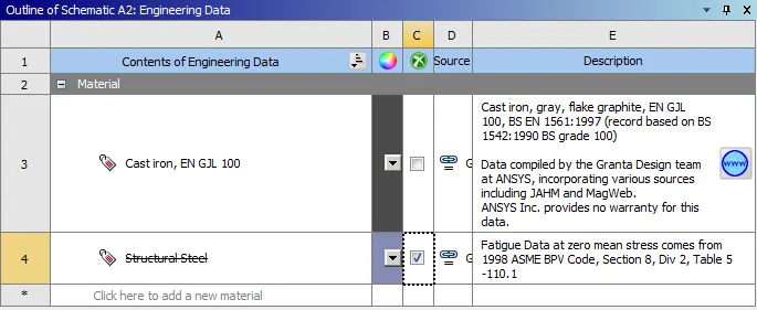
- This will add the cast iron material to the project.
- Go to GEOMETRY > IMPORT > BROWSE.
- Select the spur_gear.stp file to import the geometry.
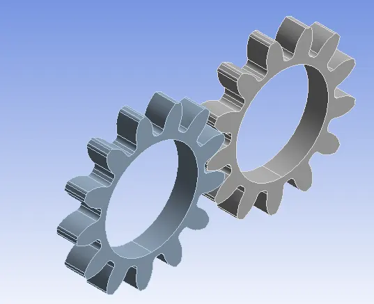
- Then, DOUBLE CLICK ON MODEL. This will open the mechanical module.
- In the Mechanical Module, first rename the gear geometry as Gear_1 and Gear_2.
- Assign material as Cast Iron to both the gears.
- Go to CONNECTIONS > CONTACTS > CONTACT FACES > TARGET FACES > TYPE = FRICTIONAL > BEHAVIOUR = SYMMETRIC > FORMULATION = AUGMENTED LAGRANGE > INTERFACE TREATMENT = ADJUST TO TOUCH.
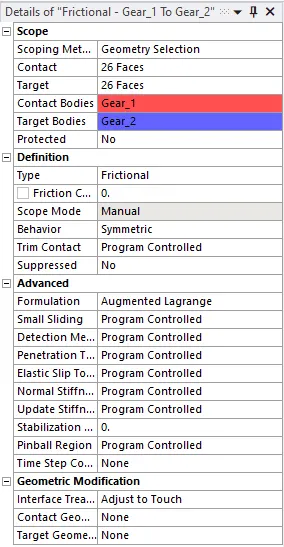
- Then, CONTACT > INSERT > JOINT > CONNECTION TYPE > BODY – GROUND > TYPE = REVOLUTE > SCOPE > APPLY.
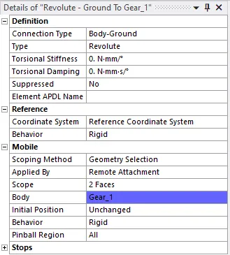
- This will introduce the gear as a revolute joint.
- Similarly, create another joint for Gear_2.
- Now, go to MESH > ELEMENT SIZE = 2MM > GENERATE MESH.
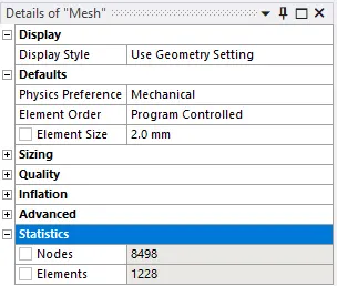
- This will create mesh on the geometry according to the code provided.
- Now, go to STATIC STRUCTURAL > ANALYSIS SETTINGS > AUTO TIME STEPPING = ON > DEFINE BY = TIME > INITIAL TIME STEP = 0.2s > MINIMUM TIME STEP = 5e-2s > MAXIMUM TIME STEP = 0.5s > LARGE DEFLECTION = ON.
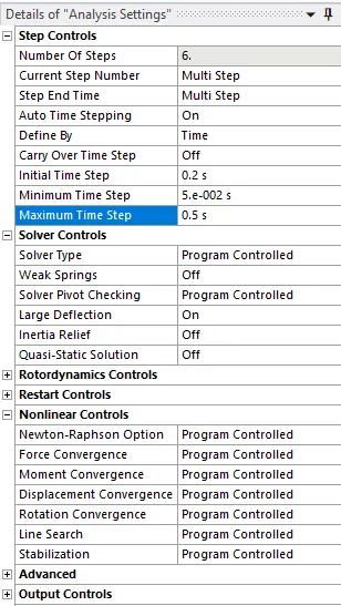
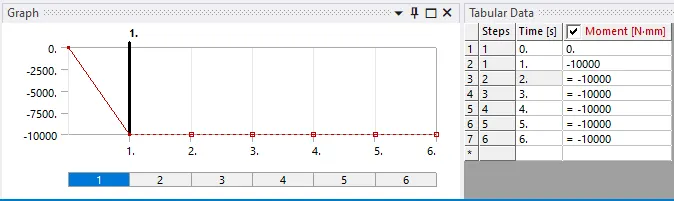
- Then, STATIC STRUCTURAL > INSERT > JOINT LOAD > JOINT = REVOLUTE –GROUND TO GEAR 1 > TYPE = ROTATION > MAGNITUDE = TABULAR DATA.
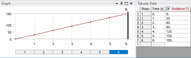
- Here, the rotation is divided into six sub-steps of 30 degrees.
- Similarly, INSERT > JOINT LOAD > JOINT = REVOLUTE – GROUND TO GEAR 2 > TYPE = MOMENT > MAGNITUDE = -10000NMM.
- Go to SOLUTION > INSERT > MAXIMUM STRESS > STRESS INTENSITY > TOTAL DEFORMATION.
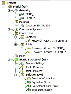
- This will define the output results to be calculated.
- Go to SOLUTION > SOLVE.
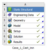
- The green tick mark defines the solution is obtained.
- Case 2 :
- For the second case, CREATE > STATIC STRUCTURAL PROJECT > CASE_2_CAST_STEEL.
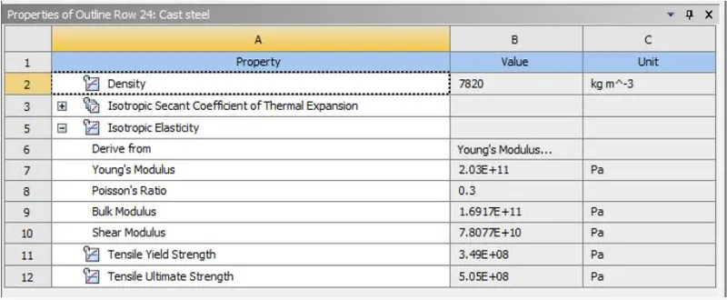
- Go to ENGINEERING DATA > CREATE NEW MATERIAL > CAST STEEL and enter the following values.
- Then, go to GEOMETRY > IMPORT > BROWSE > SPUR_GEAR.STP.
- This will import the spur gear geomerty.
- Assign Cast Steel material for Gear_1 and Gear_2.
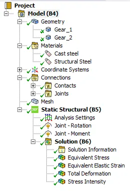
- Then, follow the similar steps as in case 1 and solve the model for cast steel material.
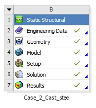
- The green tick mark defines the solution is obtained.
- Case 3 :
- For the third case, CREATE > STATIC STRUCTURAL PROJECT > CASE_3_CAST_BRONZE.
- Go to ENGINEERING DATA > CREATE NEW MATERIAL > CAST BRONZE and enter the following values.
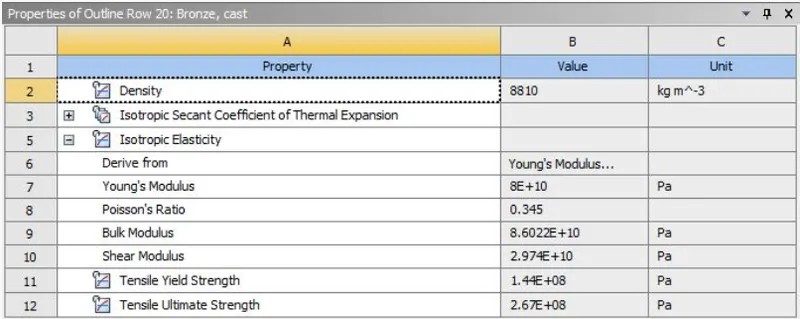
- Then, go to GEOMETRY > IMPORT > BROWSE > SPUR_GEAR.STP.
- This will import the spur gear geometry.
- Assign Cast Bronze material for Gear_1 and Gear_2.
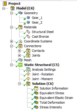
- Then, follow the similar steps as in case 1 and solve the model for cast bronze.
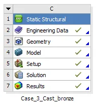
- The green tick mark defines the solution is obtained.
RESULTS:
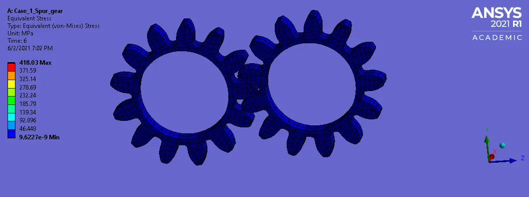
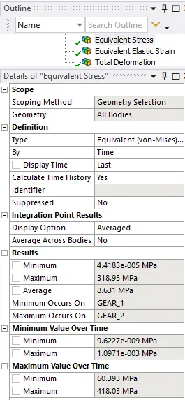
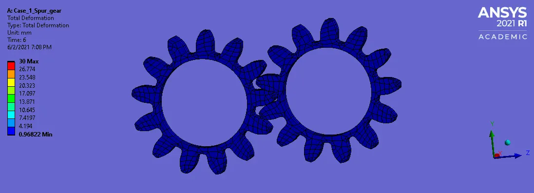
- Case 1
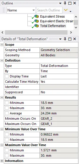
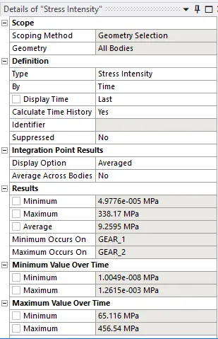
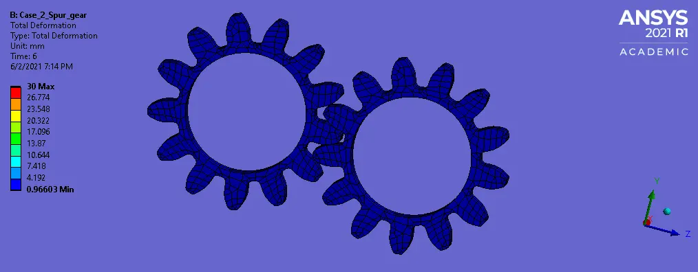
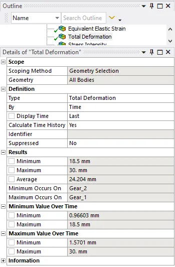
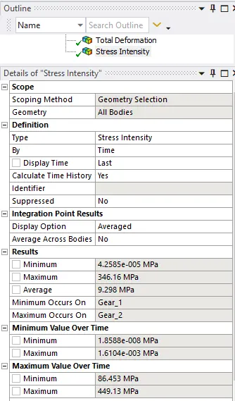
- Case 2
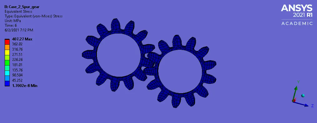
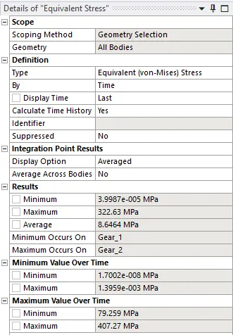
- Case 3
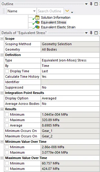
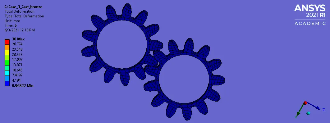
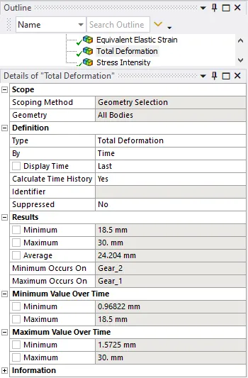
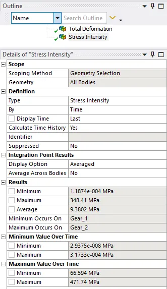
COMPARISION TABLE:
|
Stress (MPa) |
Deformation (mm) |
Stress Intensity (MPa) |
|
|
Cast Iron |
318.95 |
30 |
338.17 |
|
Cast Steel |
322.63 |
30 |
346.16 |
|
Cast Bronze |
320.89 |
30 |
348.81 |
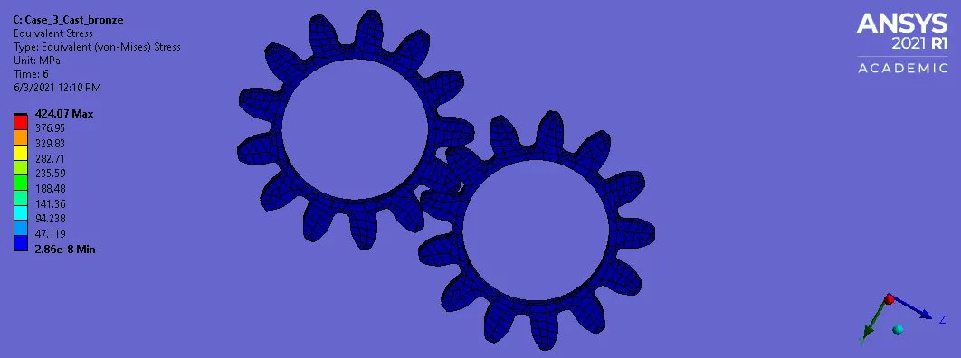
- From the table, we can conclude that Cast Iron material provides best results for stress and stress intensity.
- Cast steel and Cast bronze material induce more stress than the Cast iron material.
LEARNING OUTCOMES:
- To define material from the material library.
- To add/create material using the material properties.
- To define revolute joint for the gears.
- To define Joint loads for the gears.
- To define substeps in the analysis.
- To define the output results.
- The effect of stress intensity.
CONCLUSION:
- Hence, by performing this project, we can conclude that the Cast Iron material provides less Stress and Stress concentration values than the Cast Steel and Cast Bronze. Therefore, Cast Iron material can be recommended for the gear pair analysis.