Week 1 Spur Gear Challenge
-
Objective: To carry out a static structural analysis on spur gear with different materials and compare the results.
Using Cast Iron(ductile), Cast Bronze and Cast Steel as a material, carry out a static structural analysis to find out Equivalent stress, Total deformation and Stress intensity.
- Procedure:
Open the static structural analysis system in the Project schematic. Rename it to Case_1. Add the cast iron material in the material library in the Engineering data. After adding the material, import the spur
gear geometry and update the mechanical modeler.
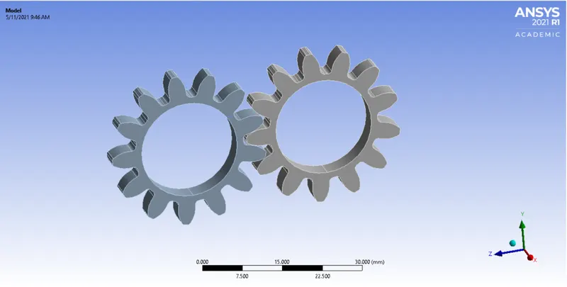
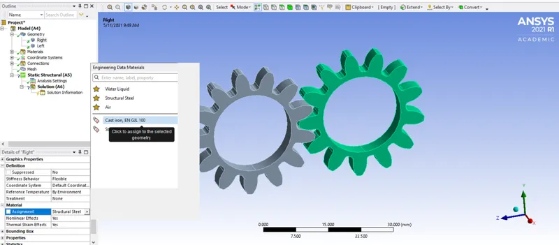
Now since the model is imported, first we need to assign material to it. By default, the material structural steel is applied. To change the material, in the Project outline, Click on Model > Geometry > Right.
Right side gear will be selected. In the Material assignment, select the Cast Iron material which we had added to the material library. Similarly, change the material of the left hand side gear.
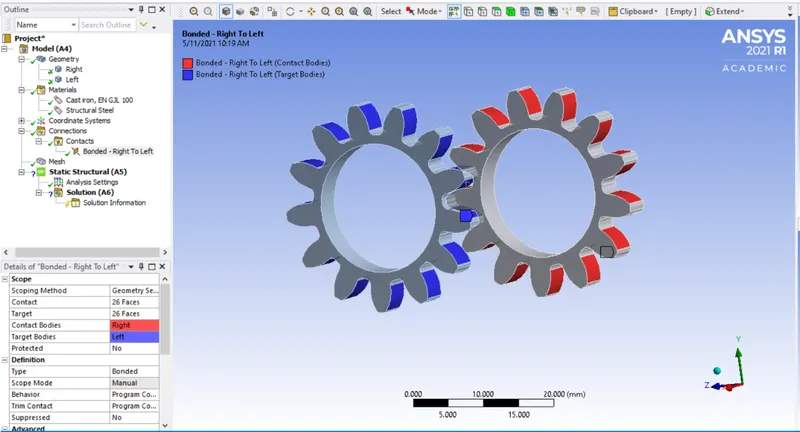
Now when there is contact between any geometries, Ansys automatically detects it and defines contact between them. Here, as seen, contact has been generated between the two gear teeth’s.
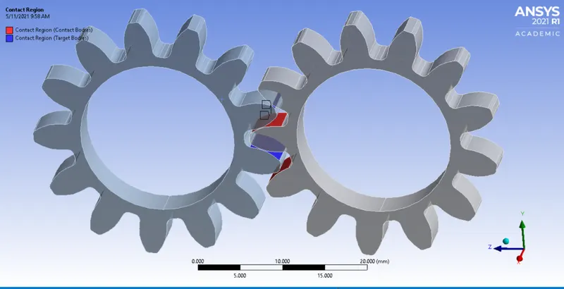
Manually update all the Target and Contact faces that will come in contact with each other throughout the simulation.
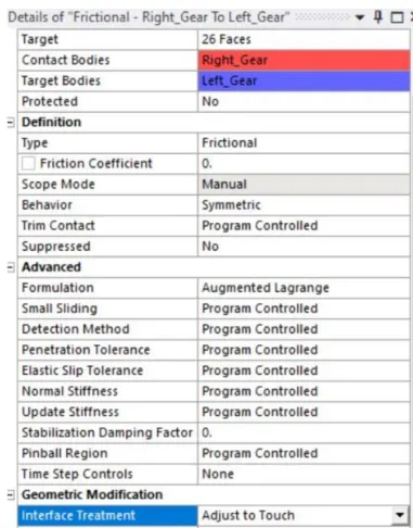
Frictional contact between the two gears is defined with the following contact properties:
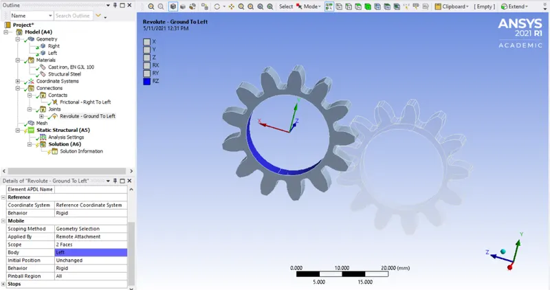
Now we need to define revolute joint to rotate the gear about an axis. Right Click on Contacts > Insert > Joints. In the Scope selector, select the inner surface of the gear as shown below. Body - Ground
connection type is used to specify reference frame. Revolute joint type is used. Similarly, define revolute joint for the other gear.
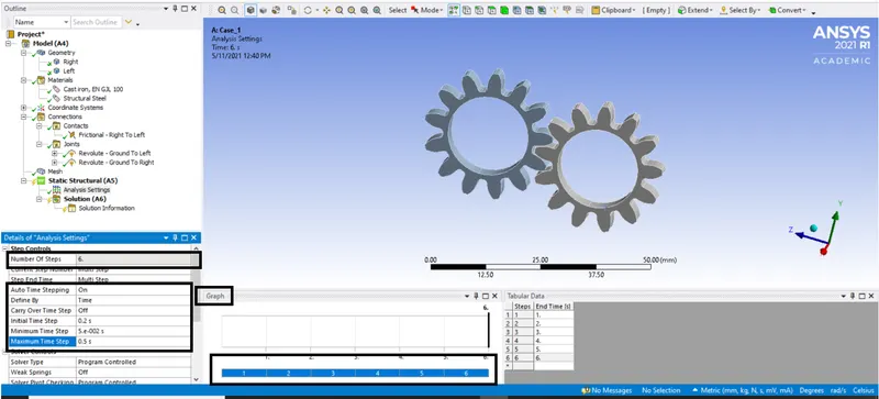
Now we want to rotate the left side gear by 180 degree. Instead of giving this rotation in one single step, divide this rotation into six steps. Click on Analysis settings and enter No. of steps = 6. Instead of
setting each individual step, select all the steps under the Graph option and set the following parameters. Also toggle the Large deflection option to On.
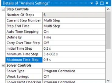
Now we can insert the joint load to define the rotation. To insert joint load, click on Static structural > Insert > Joint load. Under joint selector, select Revolute - Ground to Left joint with type as rotation. For
Magnitude, give input in tabular form as shown below.
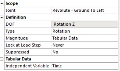
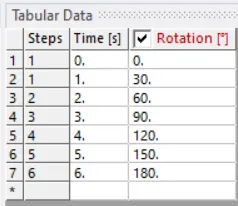
The rotation is now defined. Now specify the load on the right side gear. Insert another joint and in the joint selector, select the Revolute - Ground to Right joint with type as moment with following
magnitude:
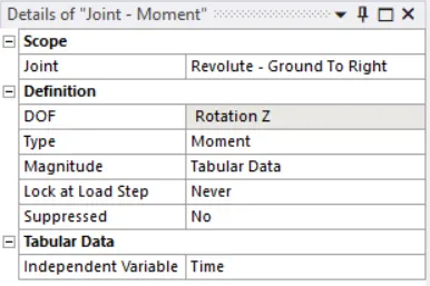
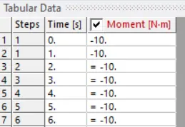
The case setup for simulation is now completed. Now run the simulation and view the results. Similarly, create case setup with Cast Bronze and Cast Steel as a material and run the simulation.
- Results:
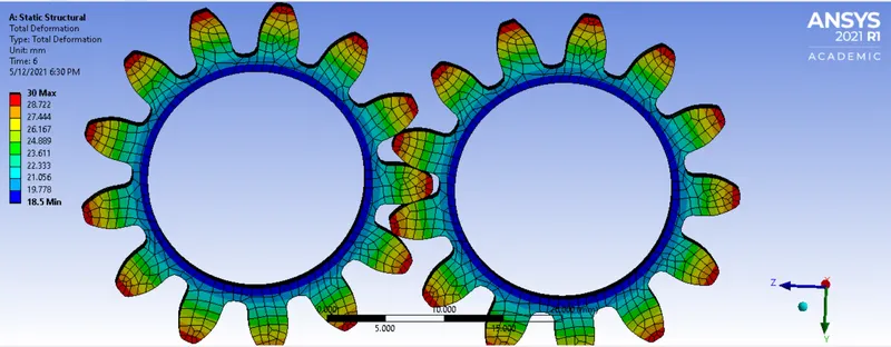
Case 1: Cast Iron.
Stress contour:
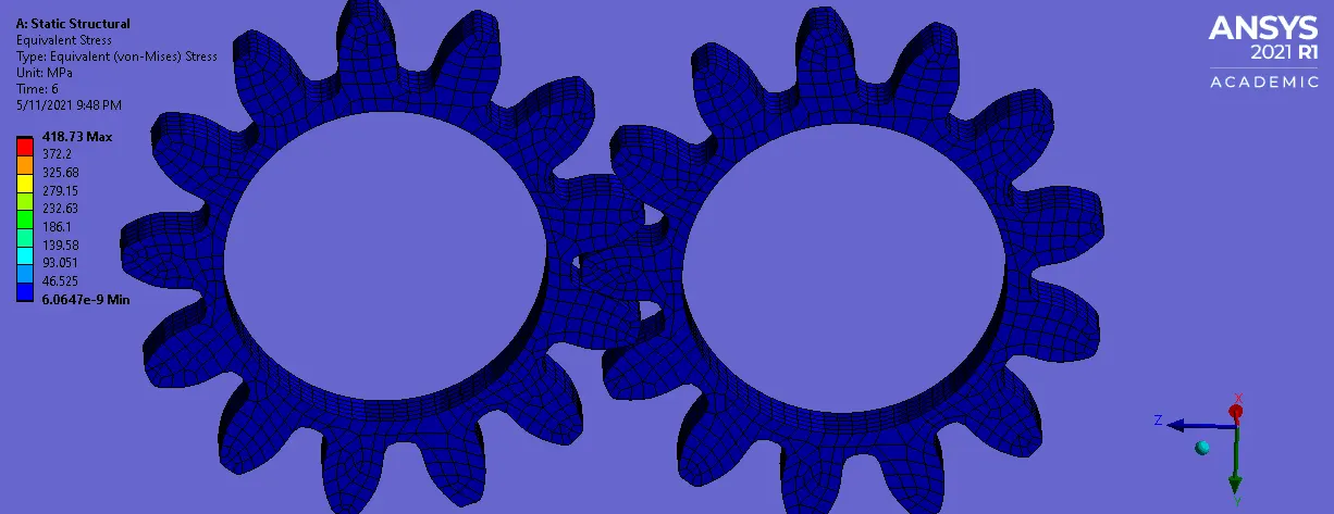
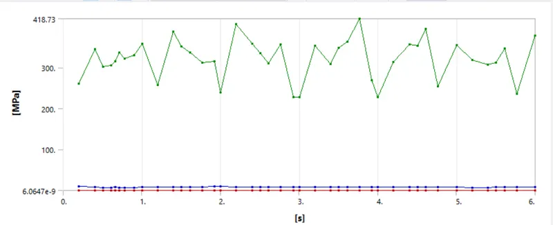
Deformation:
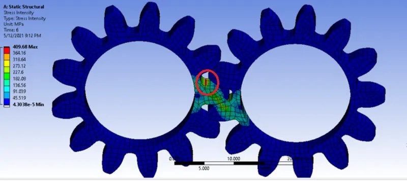
Stress Intensity: It is an alternative measure of fracture toughness. It represents the stress distribution at the tip of a crack. If a material fails locally at some critical combination of stress and strain then
it follows that fracture (crack propogation) must occur at critical stress instensity,K1C.
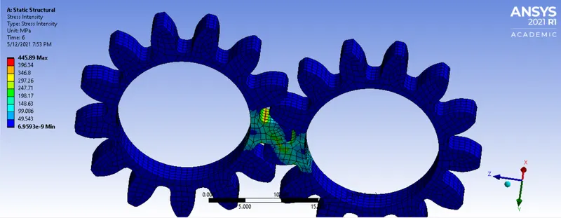
Case 2: Cast Steel.
Stress contour:
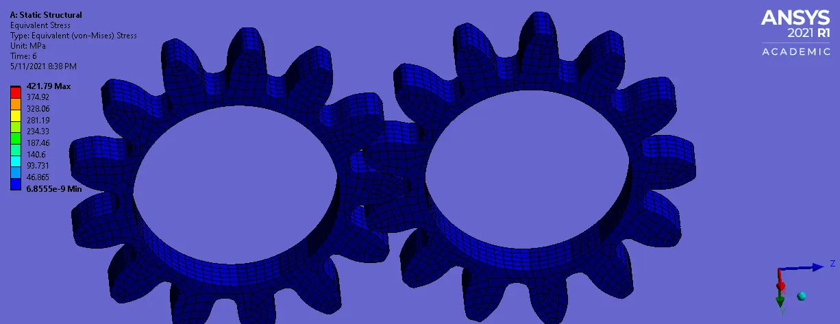
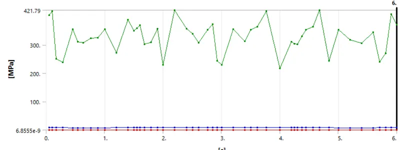
Deformation:
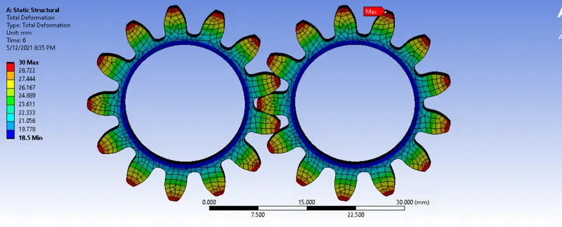
Stress Intensity:
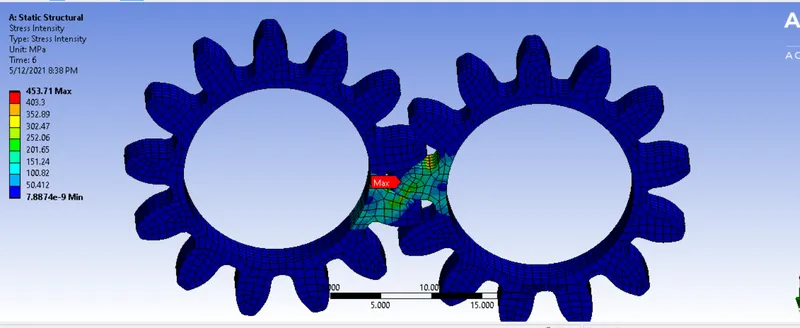
Case 3: Cast Bronze
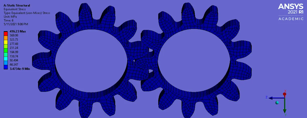
Stress contour:
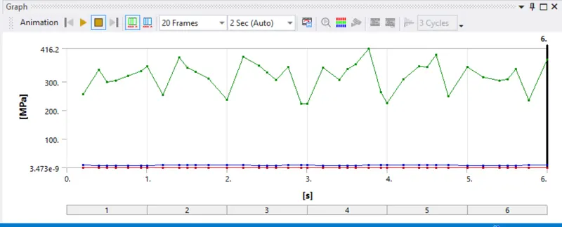
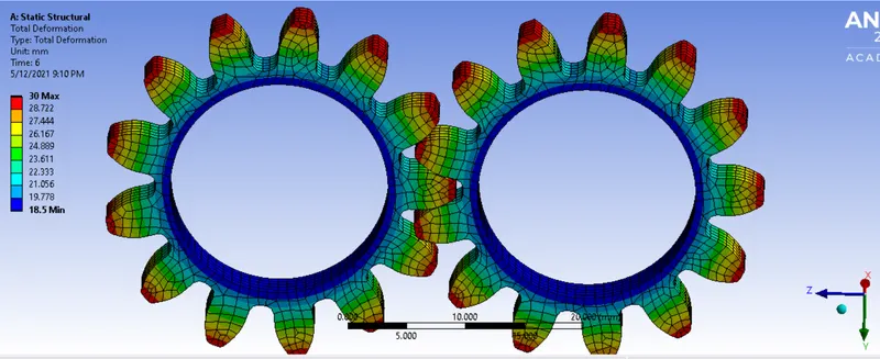
Deformation:
Stress intensity:
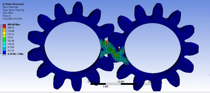

- Conclusion: Same deformation is observed for all cases. Max stress in the cast steel model is observed. From analysis point, the material with the least stress should be considered for use, i.e. Cast Bronze For all cases, max stress and max stress intensity is observed at the beginning of flank portion as indicated below. This is the possible location of fracture.