Week 1 Spur Gear Challenge
OBJECTIVE:
To perform various analysis on spur gear and conclude a better material based on our analysis. Case wise analysis is to be performed in which we are given 3 material which has to be assigned and studied.
PROCEDURE FOLLOWED:-
Import the STP file and assign engineering data to it. We have 3 cases according to which the materials has to be assigned.
Case 1 – Assign material Cast iron and calculate the equivalent stress, Total deformation & stress intensity.
Case 2- Assign material cast bronze and calculate the equivalent stress, Total deformation and stress intensity
Case 3- Assign material Carbon steel and calculate for equivalent stress, stress intensity and total deformation.
For each and every case we have to solve individually and capture data.
Starting with Gray cast iron. Gray cast iron material can be find in General material section of engineering data. After material selection edit the model in Mechanical workbench. Initially rename the gear according to their side, like right for right hand side gear and left for left hand side gear. After renaming Contacts and joints has to be assigned
Details of connections
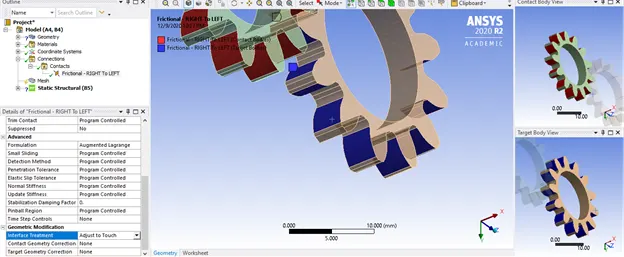
- Augmented lagrange is used because when a teeth comes in contact with other teeth, it will tend to move away from its position, to avoid harsh contact in between the teeths.
- To specify the revolute joints inserting the joints, so that the gears can move
- Specifying the parameters:
- Connection type – body to ground,
- Type of joint – revolute
- Assigning scope,
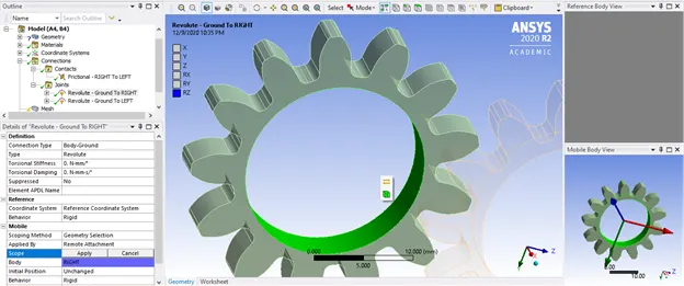
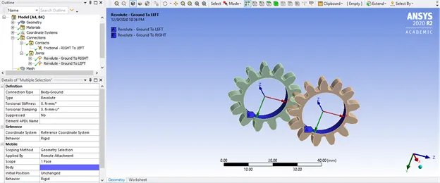
Now analysis setting has to be done:
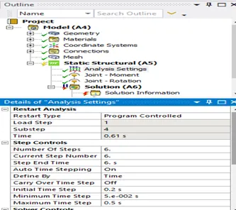
- Number of steps – 6
- Select all the 6 steps and then specify the parameters,
- Large deflection – on
- Auto time stepping – on
- Define by – Time
- Initial time step – 0.2
- Minimum time step – 5e-2
- Max time step – 0.5
After applying all this setting joint load has to be applied, so creating the joint load
Right click – insert – joint load
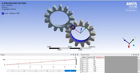
Rotation and applying the rotation to 30, 60, 90,120,150,180
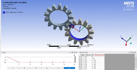
MOMENT = -10 Nm.
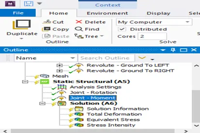
Also inserting the solution requirements as , Total deformation, equivalent stress & stress intensity.
Solving for analysis
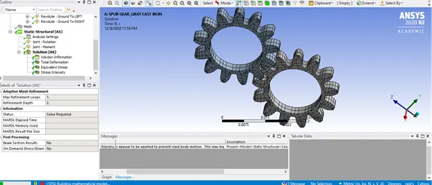
As the mesh size is slight coarse so changing the element size to 0.8 and re-meshing to make it more fine.
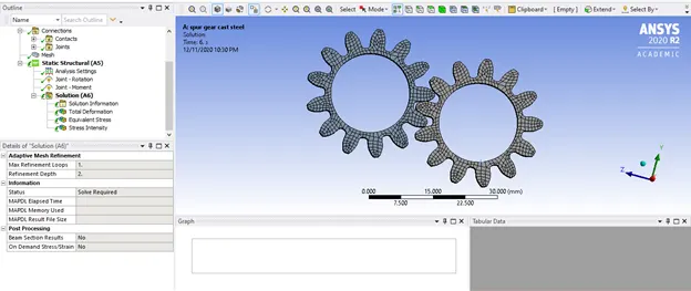
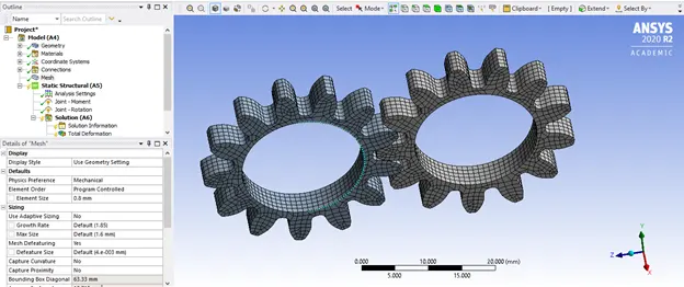
GRAY CAST IRON
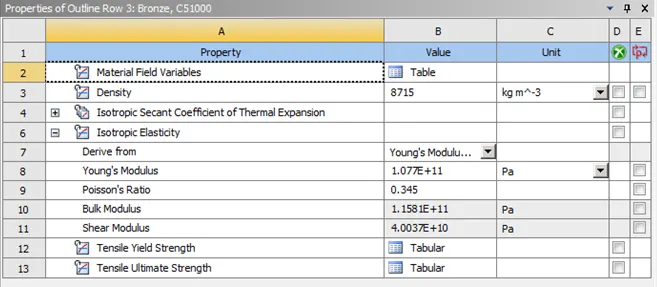
Properties for cast iron as follows:
TOTAL DEFORMATION
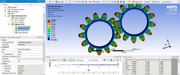
Total deformation for gray cast iron is found to be : 30 mm Maximum and 18.5 mm Minimum
|
Time |
Minimum |
Maximum |
Average |
|
0.2 |
0.96822 |
1.5883 |
1.2591 |
|
0.4 |
1.9338 |
3.1582 |
2.5092 |
|
1 |
4.7882 |
7.794 |
6.2025 |
|
1.2 |
5.7168 |
9.2965 |
7.4019 |
|
1.4 |
6.6298 |
10.774 |
8.581 |
|
2 |
9.25 |
15.025 |
11.97 |
|
2.2 |
10.076 |
16.374 |
13.041 |
|
2.25 |
10.278 |
16.69 |
13.298 |
|
3 |
13.081 |
21.23 |
16.922 |
|
3.2 |
13.748 |
22.306 |
17.784 |
|
3.4 |
14.377 |
23.32 |
18.594 |
|
4 |
16.021 |
25.988 |
20.72 |
|
4.2 |
16.484 |
26.742 |
21.317 |
|
4.25 |
16.592 |
26.915 |
21.456 |
|
5 |
17.87 |
28.988 |
23.109 |
|
5.2 |
18.096 |
29.348 |
23.398 |
|
5.4 |
18.272 |
29.633 |
23.626 |
|
6 |
18.5 |
30 |
23.92 |
STRESS INTENSITY
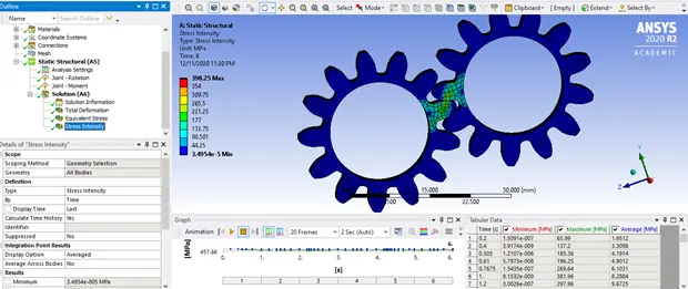
Stress intensity for gray cast iron – 398.25 MPa (Max) and 3.4954E-5 MPa (Min)
|
Time |
Minimum |
Maximum |
Average |
|
0.2 |
1.51E-07 |
65.99 |
1.9512 |
|
0.4 |
3.92E-09 |
137.2 |
3.3098 |
|
1 |
9.15E-09 |
381.96 |
8.2884 |
|
1.2 |
3.00E-07 |
297.96 |
9.6725 |
|
1.4 |
7.38E-07 |
417.64 |
9.6202 |
|
2 |
3.98E-07 |
245.74 |
9.9604 |
|
2.2 |
1.45E-06 |
426.7 |
9.486 |
|
2.25 |
6.47E-06 |
434.39 |
9.3012 |
|
3 |
8.56E-08 |
240.93 |
9.4442 |
|
3.2 |
3.69E-05 |
357.94 |
9.0104 |
|
3.4 |
2.11E-07 |
365.85 |
8.9 |
|
4 |
4.17E-08 |
253.83 |
9.7641 |
|
4.2 |
1.48E-05 |
365.97 |
9.5575 |
|
4.25 |
1.53E-05 |
333.39 |
9.3916 |
|
5 |
8.53E-06 |
397.3 |
8.2942 |
|
5.2 |
1.56E-06 |
341.57 |
7.9676 |
|
5.4 |
6.49E-06 |
331.42 |
8.0445 |
|
6 |
3.50E-05 |
398.25 |
9.8756 |
VON MISES STRESS/EQUIVALENT STRESS
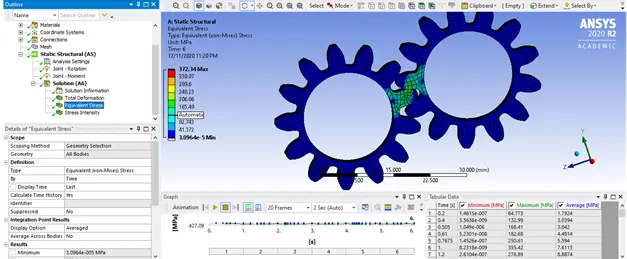
Von mises stress for gray cast iron – 372.34 MPa(Max) & 3.0946E-5 MPa(Min)
|
Time |
Minimum |
Maximum |
Average |
|
0.2 |
1.46E-07 |
64.773 |
1.7924 |
|
0.4 |
3.56E-09 |
132.99 |
3.0394 |
|
1 |
8.23E-09 |
355.42 |
7.6113 |
|
1.2 |
2.61E-07 |
278.89 |
8.8874 |
|
1.4 |
6.63E-07 |
389.36 |
8.8414 |
|
2 |
3.65E-07 |
240.2 |
9.1375 |
|
2.2 |
1.28E-06 |
399.07 |
8.7001 |
|
2.25 |
5.66E-06 |
406.27 |
8.5325 |
|
3 |
7.53E-08 |
233.75 |
8.6924 |
|
3.2 |
3.31E-05 |
344.94 |
8.2718 |
|
3.4 |
1.97E-07 |
324.42 |
8.1552 |
|
4 |
3.62E-08 |
239.56 |
8.9556 |
|
4.2 |
1.29E-05 |
335.26 |
8.7703 |
|
4.25 |
1.38E-05 |
309.53 |
8.6213 |
|
5 |
7.53E-06 |
369.85 |
7.614 |
|
5.2 |
1.39E-06 |
317.42 |
7.3015 |
|
5.4 |
5.66E-06 |
308.43 |
7.3736 |
|
6 |
3.10E-05 |
372.34 |
9.0506 |
After the Gray cast iron materials to be assigned is CAST BRONZE, it can be copied from the ANSYS GRANTA material. After assigning the material, performing the same steps and applying the required properties and solving for the stress intensity, total deformation, von mises stress.
CAST BRONZE
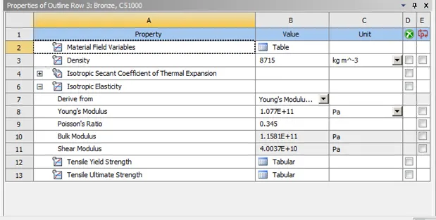
Properties of cast bronze:
TOTAL DEFORMATION
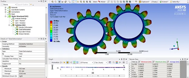
Max deformation – 30 mm
Min deformation – 18.5 mm
|
Time |
Minimum |
Maximum |
Average |
|
5.00E-02 |
0.24216 |
0.40722 |
0.31889 |
|
0.1 |
0.48427 |
0.79621 |
0.63047 |
|
0.15 |
0.72631 |
1.1956 |
0.94617 |
|
0.2 |
0.96822 |
1.5894 |
1.2595 |
|
1 |
4.7882 |
7.8062 |
6.2074 |
|
1.2 |
5.7168 |
9.3028 |
7.4044 |
|
1.4 |
6.6298 |
10.783 |
8.5848 |
|
2 |
9.25 |
15.028 |
11.971 |
|
2.2 |
10.076 |
16.371 |
13.04 |
|
2.4 |
10.874 |
17.654 |
14.068 |
|
3 |
13.081 |
21.236 |
16.924 |
|
3.2 |
13.748 |
22.308 |
17.784 |
|
3.25 |
13.909 |
22.567 |
17.992 |
|
4 |
16.021 |
25.992 |
20.721 |
|
4.2 |
16.484 |
26.744 |
21.318 |
|
4.25 |
16.592 |
26.917 |
21.457 |
|
5 |
17.87 |
28.987 |
23.108 |
|
5.2 |
18.096 |
29.349 |
23.399 |
|
6 |
18.5 |
30 |
23.92 |
STRESS INTENSITY
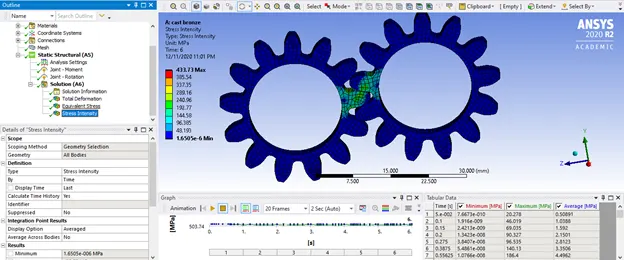
Max stress intensity – 433.73 MPa
Min stress intensity – 1.65E-6 MPa
|
Time |
Minimum |
Maximum |
Average |
|
5.00E-02 |
7.67E-10 |
20.278 |
0.50891 |
|
0.1 |
1.92E-09 |
46.019 |
1.0388 |
|
0.15 |
2.42E-09 |
69.035 |
1.592 |
|
0.2 |
1.34E-08 |
90.327 |
2.1501 |
|
1 |
1.88E-05 |
397.89 |
8.3296 |
|
1.2 |
3.92E-08 |
237.25 |
9.3354 |
|
1.4 |
5.17E-06 |
418.67 |
9.5393 |
|
2 |
1.18E-06 |
268.94 |
10.01 |
|
2.2 |
8.03E-08 |
454.09 |
9.4806 |
|
2.4 |
3.01E-08 |
374.28 |
8.9749 |
|
3 |
3.13E-08 |
258.31 |
9.7713 |
|
3.2 |
8.54E-08 |
372.24 |
9.0764 |
|
4 |
6.61E-05 |
235.16 |
9.6878 |
|
4.2 |
1.55E-07 |
332.87 |
9.3488 |
|
4.25 |
7.64E-05 |
326.55 |
9.3982 |
|
5 |
3.81E-07 |
385.09 |
8.3397 |
|
5.2 |
1.34E-06 |
345.52 |
8.0609 |
|
5.25 |
1.69E-05 |
365.69 |
8.1557 |
|
6 |
1.65E-06 |
433.73 |
10.143 |
VON MISES STRESS/EQUIVALENT STRESS
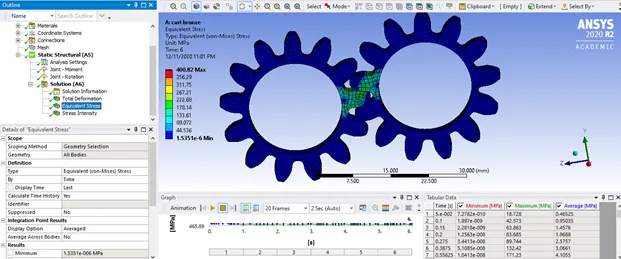
Max von mises stress – 400.82 MPa
Min von mises stress – 1.5351E-6 MPa
|
Time |
Minimum |
Maximum |
Average |
|
5.00E-02 |
7.28E-10 |
18.728 |
0.46525 |
|
0.1 |
1.90E-09 |
42.573 |
0.95035 |
|
0.15 |
2.28E-09 |
63.863 |
1.4576 |
|
0.2 |
1.26E-08 |
83.685 |
1.9688 |
|
1 |
1.65E-05 |
363.95 |
7.6199 |
|
1.2 |
3.40E-08 |
217.94 |
8.5387 |
|
1.4 |
4.85E-06 |
385.67 |
8.7386 |
|
2 |
1.02E-06 |
250.79 |
9.1507 |
|
2.2 |
6.96E-08 |
419.62 |
8.6763 |
|
2.4 |
2.63E-08 |
345.11 |
8.195 |
|
3 |
2.90E-08 |
246.9 |
8.962 |
|
3.2 |
7.48E-08 |
353.42 |
8.3034 |
|
4 |
5.83E-05 |
226.53 |
8.8587 |
|
4.2 |
1.34E-07 |
300.03 |
8.5496 |
|
5 |
3.42E-07 |
352.03 |
7.6296 |
|
5.2 |
1.20E-06 |
315.81 |
7.3618 |
|
6 |
1.54E-06 |
400.82 |
9.2744 |
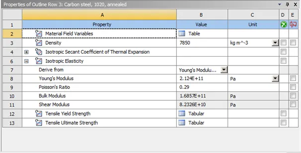
CARBON STEEL 1020 ANNEALED
Properties for carbon steels are as below:
TOTAL DEFORMATION
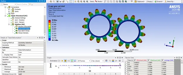
Maximum deformation – 30 mm
Minimum deformation – 18.5 mm
Tabular data for deformation is attached here with.
|
Time |
Minimum |
Maximum |
Average |
|
0.2 |
0.96822 |
1.5865 |
1.2584 |
|
0.4 |
1.9338 |
3.153 |
2.5071 |
|
1 |
4.7882 |
7.7795 |
6.1967 |
|
1.2 |
5.7168 |
9.2883 |
7.3986 |
|
1.4 |
6.6298 |
10.76 |
8.5756 |
|
2 |
9.25 |
15.017 |
11.967 |
|
2.2 |
10.076 |
16.362 |
13.037 |
|
2.4 |
10.874 |
17.641 |
14.062 |
|
3 |
13.081 |
21.227 |
16.92 |
|
3.2 |
13.748 |
22.3 |
17.78 |
|
3.4 |
14.377 |
23.315 |
18.591 |
|
4 |
16.021 |
25.987 |
20.718 |
|
4.2 |
16.484 |
26.736 |
21.315 |
|
4.25 |
16.592 |
26.909 |
21.454 |
|
4.3 |
16.698 |
27.079 |
21.59 |
|
5 |
17.87 |
28.984 |
23.107 |
|
5.2 |
18.096 |
29.345 |
23.397 |
|
5.4 |
18.272 |
29.631 |
23.625 |
|
6 |
18.5 |
30 |
23.92 |
VON MISES STRESS
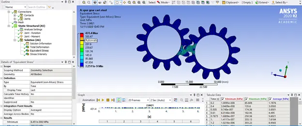
Maximum value for von mises – 431.4 MPa
Minimum value for von mises – 7.2511e-9 MPa
Tabular data for von mises :
|
Time |
Minimum |
Maximum |
Average |
|
0.2 |
1.01E-08 |
85.608 |
1.7876 |
|
0.4 |
3.94E-08 |
135.6 |
3.0593 |
|
1 |
1.41E-07 |
355.13 |
7.6184 |
|
1.2 |
1.02E-06 |
303.22 |
8.9565 |
|
1.4 |
2.34E-06 |
388.85 |
8.8506 |
|
2 |
7.08E-06 |
270.61 |
9.142 |
|
2.2 |
3.14E-08 |
398.23 |
8.7031 |
|
2.4 |
7.25E-09 |
371.15 |
8.3016 |
|
3 |
1.49E-07 |
243.95 |
8.7013 |
|
3.2 |
2.59E-05 |
344.33 |
8.2836 |
|
3.4 |
1.60E-07 |
323.19 |
8.1587 |
|
4 |
2.95E-08 |
234.77 |
8.9543 |
|
4.2 |
3.99E-06 |
334.67 |
8.7801 |
|
4.25 |
5.84E-05 |
309.99 |
8.6269 |
|
5 |
3.43E-07 |
369.44 |
7.6267 |
|
5.2 |
1.75E-07 |
316.97 |
7.3137 |
|
5.4 |
1.19E-07 |
307.89 |
7.3739 |
|
6 |
6.45E-06 |
389.02 |
9.5994 |
STRESS INTENSITY
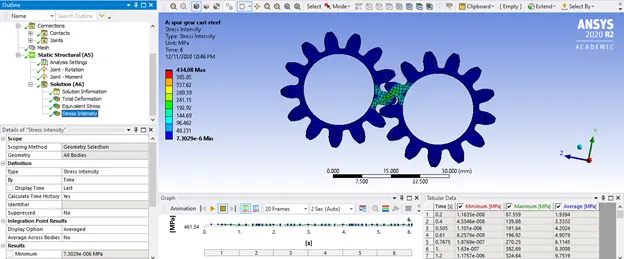
Maximum stress intensity – 434.08 MPa
Minimum stress intensity – 7.3029e-6 MPa
Table for stress intensity:
|
time |
Minimum |
Maximum |
Average |
|
0.2 |
1.16E-08 |
87.559 |
1.9394 |
|
0.4 |
4.53E-08 |
139.88 |
3.3332 |
|
1 |
1.63E-07 |
382.69 |
8.3008 |
|
1.2 |
1.18E-06 |
324.64 |
9.7519 |
|
1.4 |
2.70E-06 |
417.85 |
9.6348 |
|
2 |
8.13E-06 |
277.81 |
9.9712 |
|
2.2 |
3.59E-08 |
426.65 |
9.4935 |
|
2.4 |
8.23E-09 |
398.15 |
9.0681 |
|
3 |
1.63E-07 |
252.12 |
9.4581 |
|
3.2 |
2.92E-05 |
358.17 |
9.027 |
|
3.4 |
1.84E-07 |
363.85 |
8.9071 |
|
4 |
3.40E-08 |
249.14 |
9.7675 |
|
4.2 |
4.45E-06 |
372.67 |
9.5729 |
|
4.25 |
6.20E-05 |
334.49 |
9.4026 |
|
5 |
3.82E-07 |
397.93 |
8.3123 |
|
5.2 |
1.98E-07 |
341.95 |
7.9845 |
|
5.4 |
1.32E-07 |
331.47 |
8.0497 |
|
6 |
7.30E-06 |
434.08 |
10.469 |
CONCLUSION:-
Comparing all the data for all the 3 materials we obtained after analysis,
|
Total deformation(in mm) |
Von mises stress(in MPa) |
Stress intensity(in MPa) |
|||||||||||||
|
GRAY CAST IRON |
|
|
|
||||||||||||
|
CAST BRONZE |
|
|
|
||||||||||||
|
CARBON STEEL |
|
|
|
The values for all the three materials are attached above. From the above comparison we can conclude that from fracture view point the CARBON STEELS gears must be AVOIDED because of the reason of having the greatest stress intensity and von-mises stress among other two.
Also it can be seen that in my analysis the stress values for CAST IRON material is less comparatively. So accordingly CAST IRON gears are RECOMMENDED for gears.
For reference i have attached below the links of video files exported from workbench.