Week 1 Spur Gear Challenge
Aim: To perform a static analysis on spur gear using three different materials (Cast iron(ductile), Cast steel, and Cast bronze) and to find out Equivalent stress, Total deformation, Stress intensity also the location of failure.
Principle:
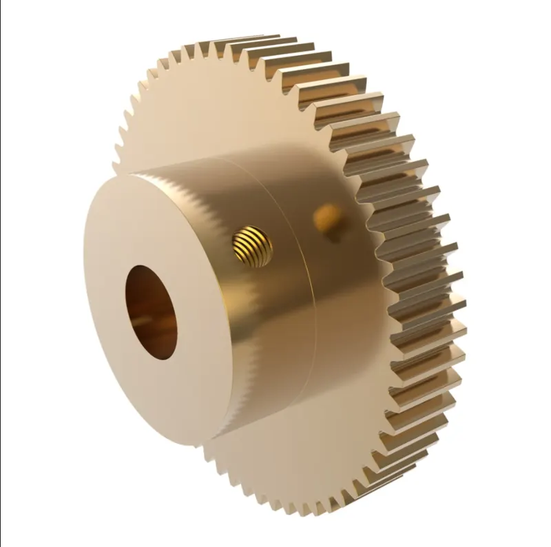
Spur gears or straight-cut gears are the simplest types of gear. They consist of a cylinder or disk with teeth projecting radially. Viewing the gear at 90 degrees from the shaft length (side on) the tooth faces are straight and aligned parallel to the axis of the rotation. Looking down the length of the shaft, a tooth's cross section is usually not triangular. Instead of being straight (as in a triangle) the sides of the cross-section have a curved form (usually involute and less commonly cycloidal) to achieve a constant drive ratio. Spur gears mesh together correctly only if fitted to parallel shafts.No axial thrust is created by the tooth loads. Spur gears are excellent at moderate speeds but tend to be noisy at high speeds.
Spur gear can be classified into two pressure angles, 20° being the current industry standard and 14½° being the former (often found in older equipment). Spur gear teeth are manufactured as either involute profile or cycloidal profile. When two gears are in mesh an involute portion of one may contact a non-involute portion of the other gear. This phenomenon is known as "interference" and occurs when the number of teeth on the smaller of the two meshing gears is less than the required minimum. Undercutting (cutting the tooth narrower closer to its base) is sometimes used to avoid interference but is usually not suitable because the decreased thickness leaves the tooth weaker at its base. In this situation, corrected gears are used. In corrected gears, the cutter rack is shifted upwards or downwards
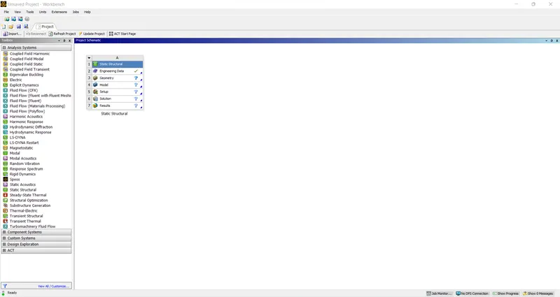
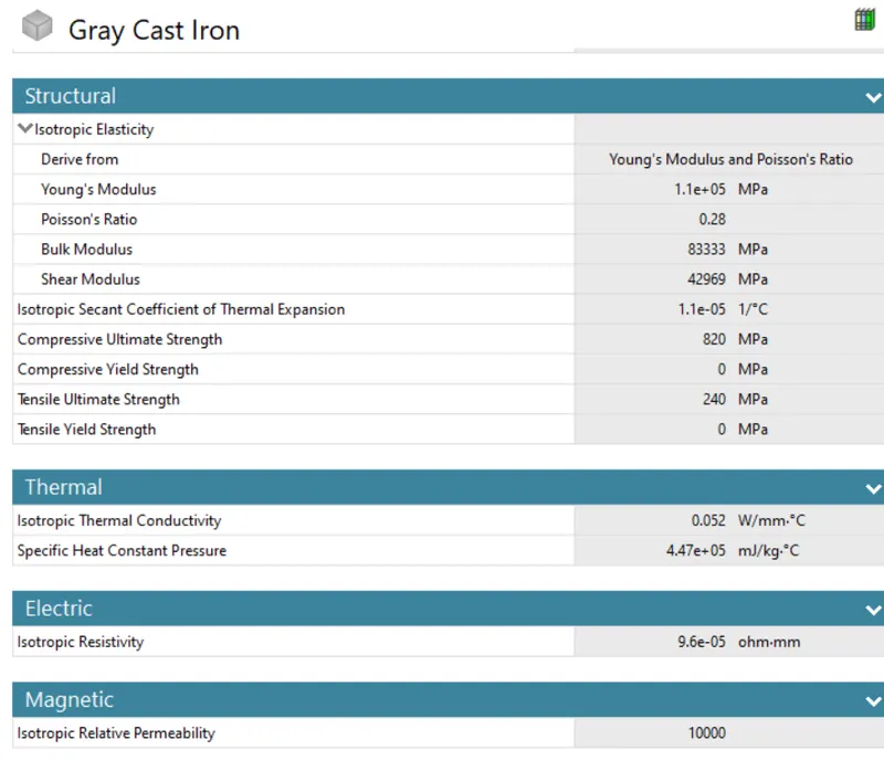
Since we are doing static structural model analysis, Static structural is selected and cast iron is selected as the material
Before we can begin analysis we need to create a model with the given dimensions but since the model is already given it is imported using the import option in the geometry
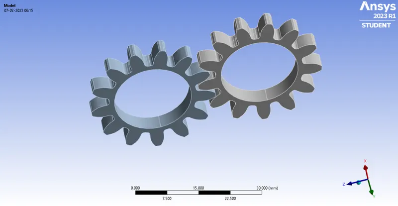
Once the 3D model is uploaded meshing has to be done on the model due to the limitations of the Ansys student edition the elements cannot exceed over 128K hence the size of the element is taken as 1
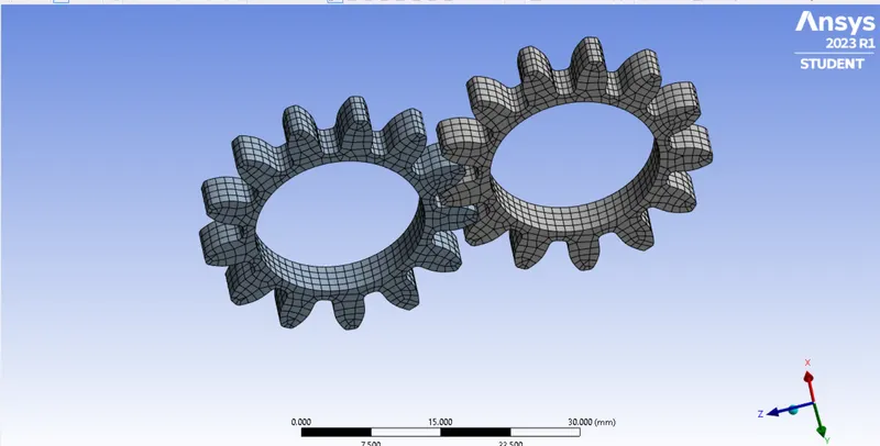
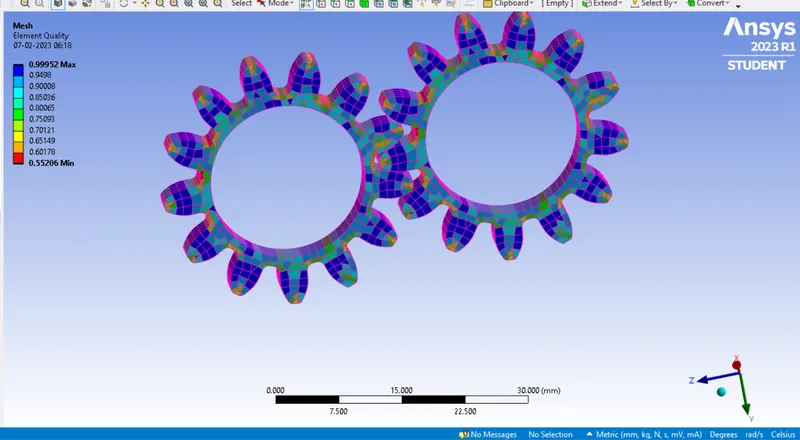
A mesh matrix that decides the quality of the element is employed and from the graph given below it can be seen that most of the elements lie between the range of 0.5 to 1.0
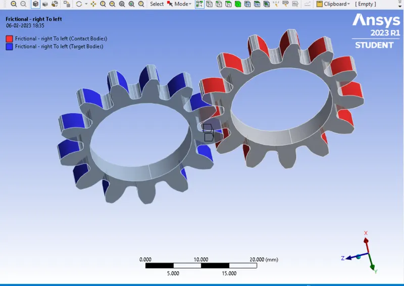
Since two gears always are in contact all the surfaces are selected in the contact options
A joint is defined as gears to rotate about an axis. A revolute type of joint was defined for both parts. This can be done using right-click contact>insert>joint. Connection type was defined as body-ground (Specifying the frame of reference), and type as revolute. Now select the inner surface to define the scope as shown below.
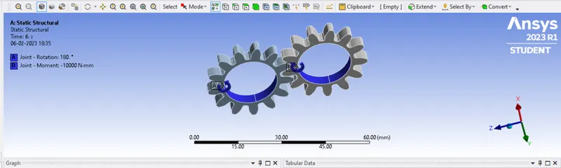
For Analysis In static structural assign the joints to the left gear and right gear as rotation and a moment.
The left gear is assigned as rotation and the right gear is assigned as a moment.
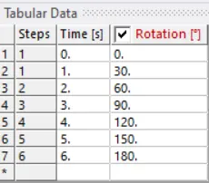
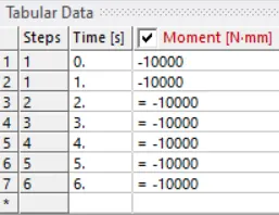
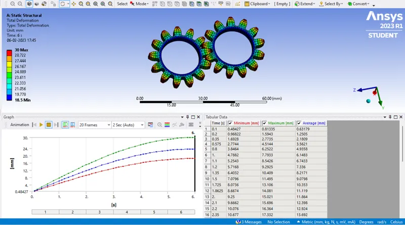
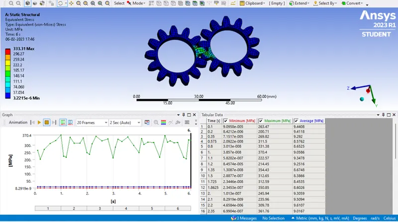
Case 1: Using Cast Iron(ductile) as a material, carry out a static structural analysis to find out Equivalent stress, Total deformation, and Stress intensity(Learn about what stress intensity is). Find the location for possible fracture
Results
1:Total deformation
2:Stress
3:Strain
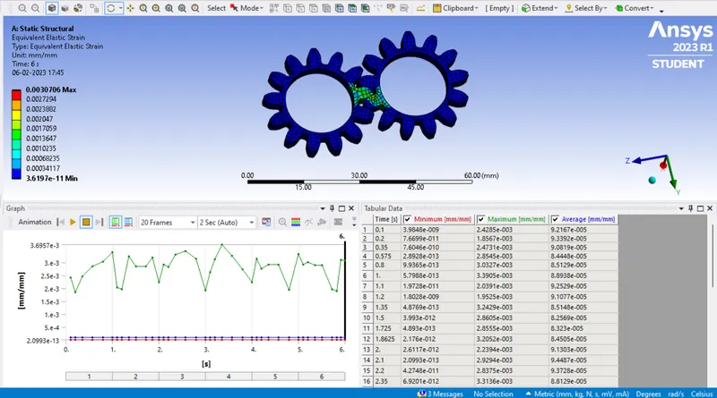
Case 2: Using Cast Steel as material, perform the same analysis for the results as in Case 1.
Results
1: Total deformation
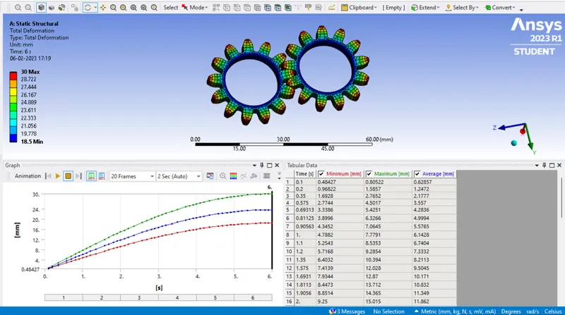
2:Strain
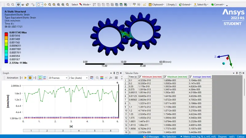
3:Stress
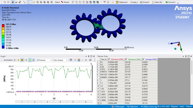
Case 3: Using Cast Bronze as material, perform the same analysis for the results as in Case 1.
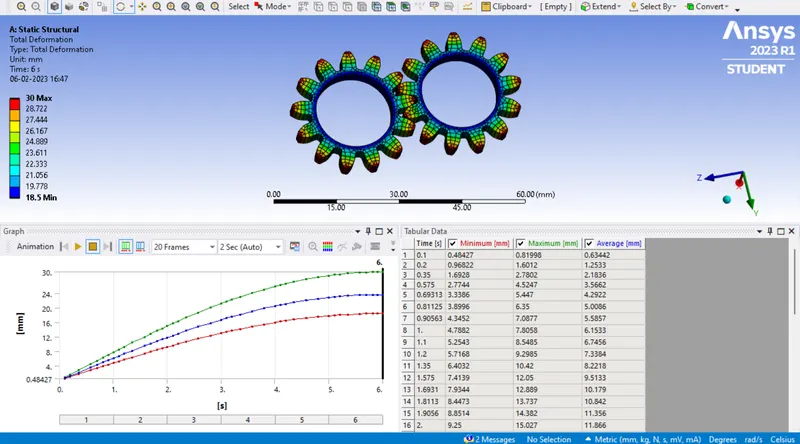
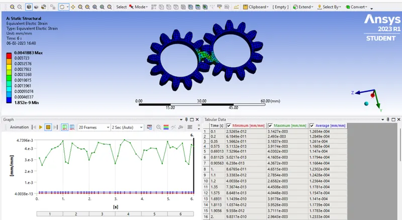
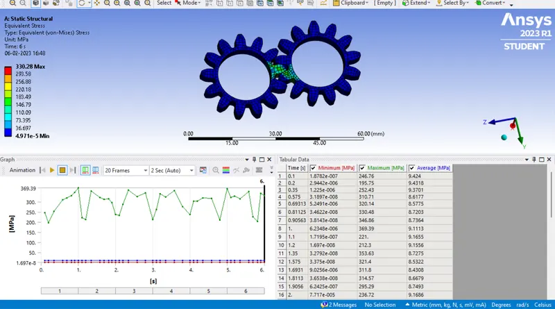
Results
1:Total Deformation
2:Strain
3:Stress
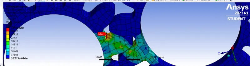
Stress intensity
Stress Intensity (Tresca Stress ) is one of the representations of equivalent stress. Stress intensity is based on the maximum shear stress failure criterion.
The maximum shear stress criterion, also known as the Tresca yield criterion, is based on the Maximum Shear stress theory.
This theory predicts the failure of a material to occur when the absolute maximum shear stress (τmax ) reaches the stress that causes the material to yield in a simple tension test.
Conclusion:
On comparing the results of cast iron, cast bronze, and cast steel it is found that cast bronze can be chosen as the preferred material since the stress intensity was found to be less thus making it less prone to failure and the least preferred material is cast iron
Link:https://drive.google.com/drive/folders/1SFC9vkG7CU2CBDcMEimnou4PcZyVEK1M?usp=share_link