Week 1 Spur Gear Challenge
OBJECTIVE :-
1. Carry out a static structural analysis to find out Equivalent stress, Total deformation and Stress intensity(Learn about what stress intensity is). Find location for possible fracture for all three materials.The given Materials are Cast Iron, Cast Steel, Cast Bronze
2. To understand the inclusion/addition of material in ansys library.
3. To learn about the type of contacts
4. To learn about the contact stetting used during the operation of two gears.
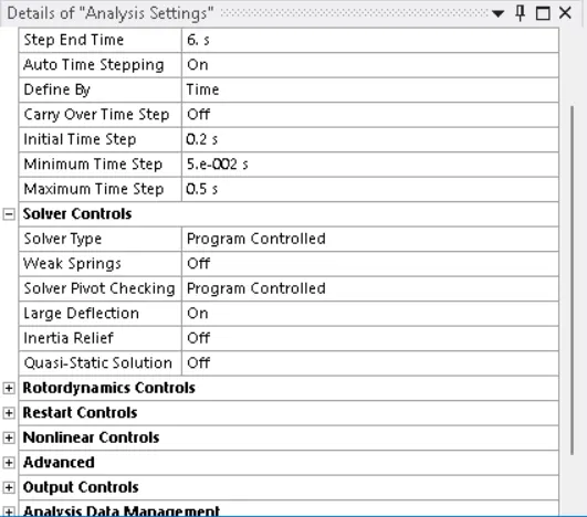
5. To apply the time step for above mention set of problem.
6. Apply the boundary conditions such as DOF and Input Moment to given set of gears.
Theory :-
1. Stress Intensity :- It is defined as largest absolute values of difference between principle stresses.


2. The Properties of the material given as follows :-

3. Different types of contact in Ansys:-
a. Bonded: As the name suggests, it allows the user to define a contacting surface like a glued surface. This type of contact does not allow any sliding or separation to take place.
b. No Separation: This type of contact allows only sliding to take place. The contact area will not separate.
c. Frictionless: In this type of contact, separation and sliding are both allowed. The coefficient of friction is taken as zero in this case. The user should check the model if it is properly constrained whenever this contact model is used. Weak springs are often added for easier convergence with this model.
d. Rough: This is similar to the frictionless type of contact except that the coefficient of friction in this case is taken as infinite.
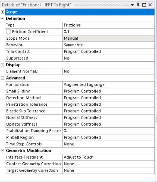
e. Frictional: We can specify any non-negative value as the frictional coefficient. So,the contact will handle shear stresses up to what is specified by the frictional coefficient. After this value, sliding will start to take place.
5. Formulation : is one of the Advanced setting in ANSYS Structural used to define the behaviour of the contacts that we specify. There are different algorithms that are used to specify the type of contact pair computation. Depending on the type of algorithm used, the system can behave differently. There are 5 algorithms used in ANSYS but 6 settings to
choose from. The last one is a “Program Controlled” option where the ANSYS solver chooses the algorithm.
The different algorithms used are:
1. Pure Penalty
2. Normal Lagrange
3. Augmented Lagrange
4. MPC( Multi Point Constraints)
5. Beam
6.Contact and Target bodies In an interface, we define the contact and target. While deciding between these two, we should keep in mind that ANSYS considers the contact body as the one which is not allowed to penetrate into the target body. But the target is allowed to penetrate into the contact body. If you are unsure of the behaviour of your system, then you can choose Symmetric type of contact. Otherwise, an Asymmetric type of contact can be used.
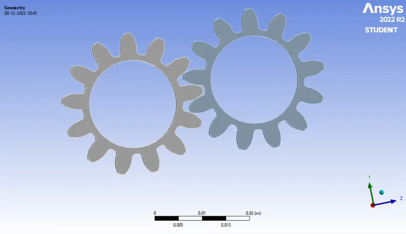
CAD Model
PROCEDURE
1. Initially the Static Structural was selected as solver Sysytem. The next step was to assign the material to the cad model. if the materal is not present in the Engineering data then the same needs to be added in the data from the library.
2. The Cad Model was imported and nomenclature was assigned to the geometry.
3. After this the contact settings were assigned to the teeth of the gear. The Contact settings us is as follows :-
4. Post this the degree of freedom was aloted to the cad model, and the same are as follows :-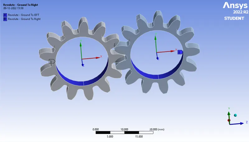
5. After this Analysis settings are assigned in the solver and the same are as follows:-
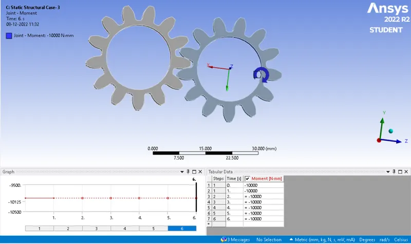
6. For the solving part the Moment was defined as follows :-
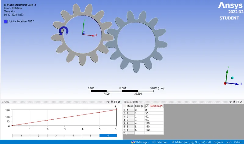
7. The angle of rotation assigned to eah time step is as follows :-
RESULTS
The results on the simulation undertaken case wise are as follows :-
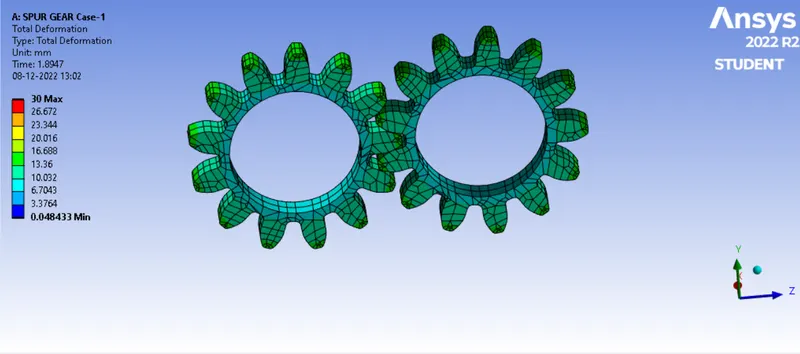
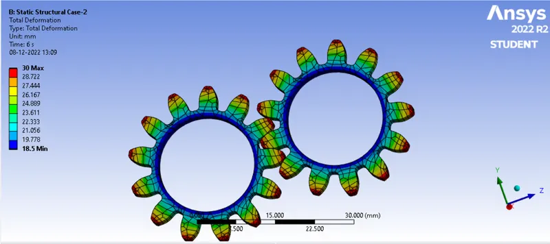
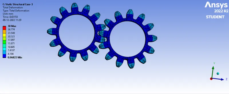
1. Total Deformation
Case-1 Gears with Moc Cast Iron
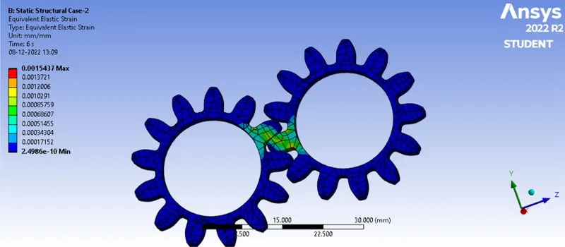
Case-2 Gears with Moc Cast Steel
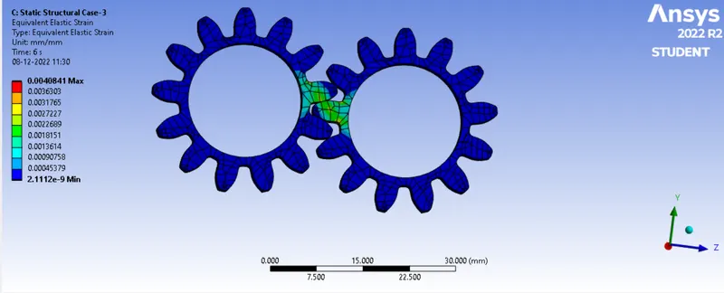
Case-3 Gears with Moc Cast Bronze
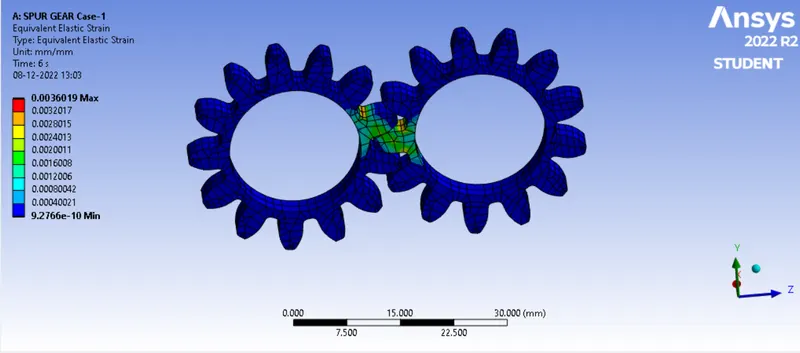
2. Equivalent Strain
Case-1Gears with Moc Cast Iron
Case-2Gears with Moc Cast Steel
Case-3Gears with Moc Cast Bronze
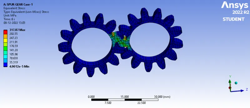
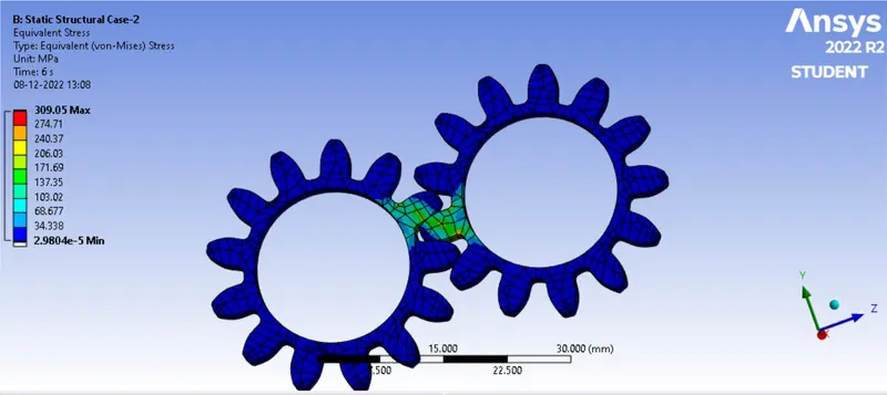
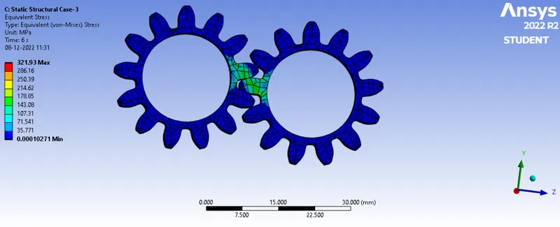
3. Equivalent Stress
Case-1Gears with Moc Cast Iron
Case-2Gears with Moc Cast Steel
Case-3Gears with Moc Cast Bronze
Tabular representation of the findings are as follows :-
| SL.NO | Material | Total Deformation | Equivalent Strain | Equivalent Stress | Stress Intensity |
|
1. |
Cast Iron |
Min 18.5mm Max 30mm |
Min 1.69e-10 mm/min Max 3.60e-3mm/min |
Min 8.4 Pa
Max 317.95 MPa |
348.74MPa |
|
2. |
Cast Steel |
Min 18.5mm Max 30mm |
Min 2.4989e-10 mm/min Max 1.543e-3mm/min |
Min 29.804 Pa Max 309.05 MPa |
342.34MPa |
|
3. |
Cast Bronze |
Min 18.5mm Max 30mm |
Min 2.1112e-9 mm/min Max 4.0841e-3mm/min |
Min 102.7 Pa Max 321.93 MPa |
351.91 MPa |
CONCLUSION
1. After the comparing the total deformation for all the cases it was observed that total deformation was same for all the gears with different materials.
2. The Gear with highest generation of equvalent stress was the one with MOC as Cast Bronze.on comparision with its tensile strength it can be concluded that the material has yielded during its operation.
3. The gear which is more safer among three MoCs is the one which is made of cast Steel. it has highrer tensile yield strength and is generating lower Equivalent Stress under its operation.