Simulation of Spur Gear using Ansys
Objective
- To mesh the spur gear model.
- To apply the boundary conditions.
- To do the analysis setting.
- Evaluate the results.
- To find out the stress, deformation, and stress intensity in spur gears.
- To carry out this simulation in three different cases, using cast iron material, cast steel material, and cast bronze material.
Procedure
For simulating this case, the Static Structural module was chosen, for the three cases.
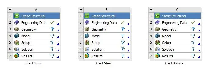
Figure 1: Static Structural module was chosen for this work.
Now as mentioned in the objective, the three cases differ in the use of a type of material. Therefore, using Engineering Data, of the Static Structural module these three materials were input, as shown below.
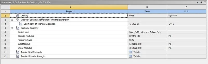
Figure 2(a): Material card of cast iron for case 1.
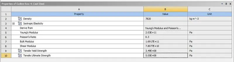
Figure 2(b): Material card of cast steel for case 2.
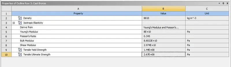
Figure 2(c): Material card of cast bronze for case 3.
Now, the spur gear model was imported and using the Model section of the Static Structural module, both the gears were first assigned with the material respect to the no. of the case, and then the mesh was performed on it, using by default elements of 0.5 mm element size, as shown in figures below. Because Ansys found it sweepable, therefore it performed mesh using hexahedral elements.
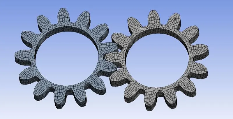
Figure 3: Meshing of gears.
Boundary Conditions
Contact
In boundary conditions, firstly, the contact had to define. The Ansys automatically found out the neighboring faces of different bodies and created a bonded contact between them. But when the gear rotates, all of its teeth comes in contact one after another. This information had to be input manually, therefore, the existing contact card was modified, and all the surfaces that could come in contact while rotating were selected, and made a friction contact between them.
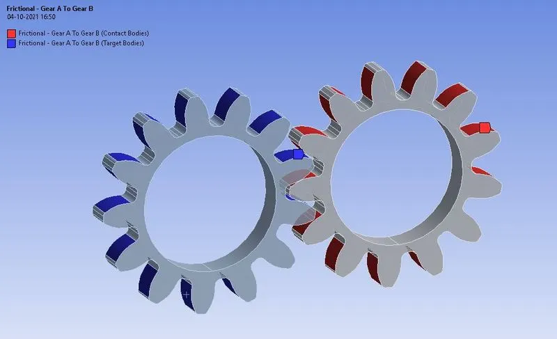
Figure 4: Contact defined for two gears.
In the figure shown above, in the top left corner, it can be observed that one gear is the contact body, and the other is the target body. Now, because it was unsure which is master and which is slave, the behavior of formulation was kept as symmetric. Also, the contact formulation was selected as Augmented Lagrange. It is because, it ensures extra stiffness, and thus less penetration.
Joint
After contact, a revolute joint had to define for both gears. Thus, it was created with, connection type as Body-Ground.
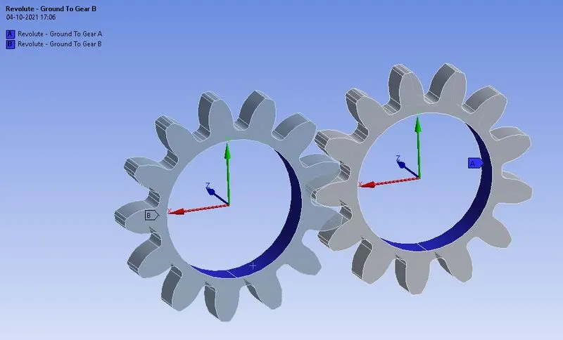
Figure 5: Revolute joint for two gears.
In the analysis set, the number of steps was divided into 6 steps. Then, the joint load was applied to both the gears. The load for the first gear was defined in tabular form as shown below.
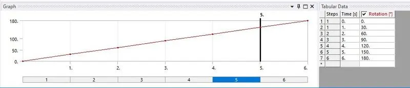
Figure 6: Rotational joint load to gear A.
To the second gear, the joint load was given in terms of the moment, equal to 10 N-m or 0.01 N-mm.
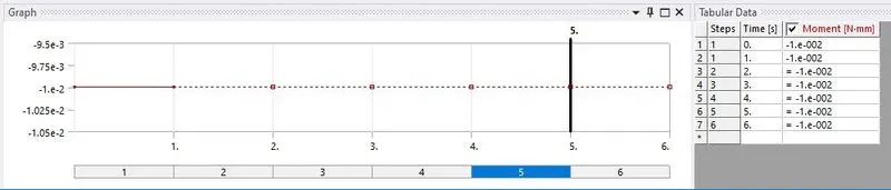
Figure 7: Moment to gear B.
Similar boundary conditions were applied in each case. After setting, all the constraints required for the problem, it was then solved. In the result, Equivalent (Von-Mises) stress, Total Deformation, and stress intensity results were requested. After ensuring that the model was ready for the simulation to solve, the problem was solved.
Post-processing
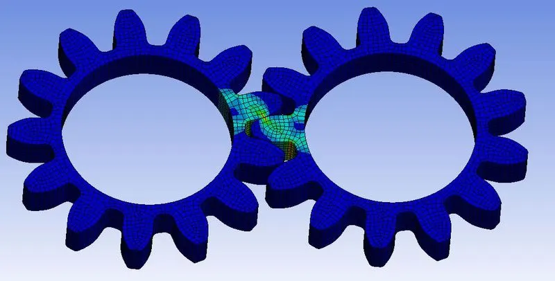
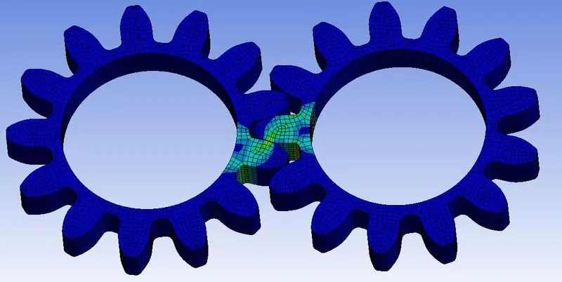
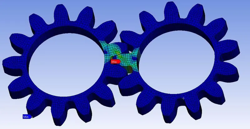
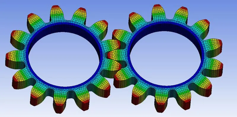
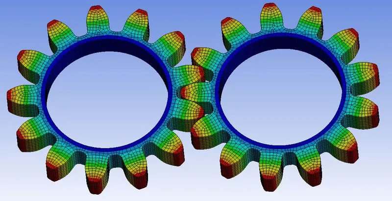
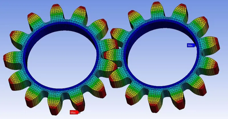
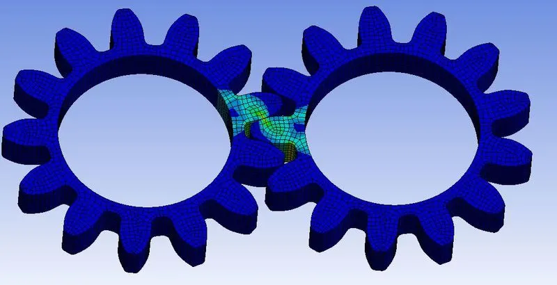
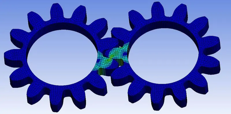
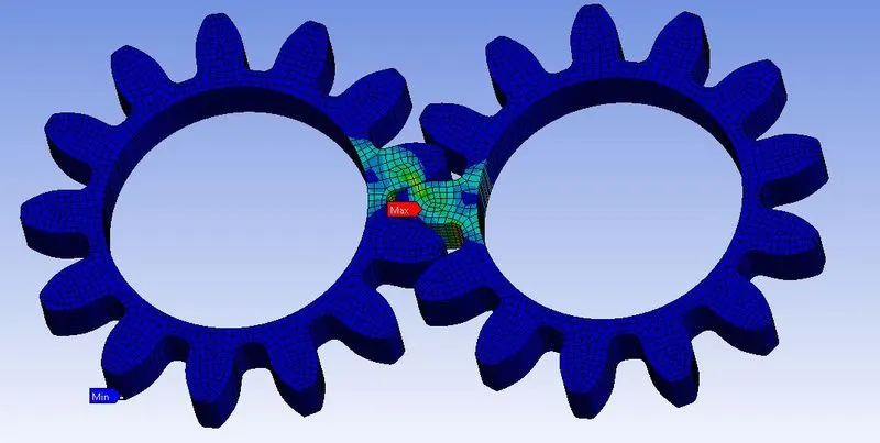
The table below shows the comparison between every three cases. From the three cases, although the maximum Von-Mises stress of all the cases is beyond its yield strength, which means, practically, the tooth should break (in a brittle manner, because it is cast), but it is not because the software is not showing the failure. It just shows the maximum and minimum values.
|
Cast Iron |
Cast Steel |
Cast Bronze |
|
|
Von-Mises Contour |
 |
 |
 |
|
Max. Von-Mises Stress (in MPa) |
465.54 |
457.34 |
441.73 |
|
Total Deformation |
 |
 |
 |
|
Maximum Deformation (in mm) |
30 |
30 |
30 |
|
Stress Intensity |
 |
 |
 |
|
Maximum Stress Intensity (in MPa) |
525.7 |
515.52 |
492.24 |
Yet, the deformation is the same for all the cases, but the stress-induced in cast iron is greater than in the other two cases, which shows the greater chance of failure. Now, the stress intensity is the fracture mechanics term used to signify the stress concentration in the vicinity of the crack. It is compared to the fracture toughness or the critical value to predict the failure in the component.
CONCLUSION
In this work, three cases were compared. In the first case, cast iron material was used, in the second cast steel, and in the third cast bronze material was used. After performing the simulation, it is found that cast iron material has undergone greater stress concentration, as compared to the other two. Greater stress concentration means a greater chance of failure. However, cast bronze material has shown comparably better performance against failure. And the cast steel remained in-between the two. Thus, according to the analysis point of view, instead of cast iron, cast steel, and cast bronze material should be preferred for the manufacturing of gears.