Week 1- Mixing Tee
AIM:
To perform the steady state simulations of hot and cold air in a Mixing Tee component.
INTRODUCTION:
- Mixing of fluids in T-junction geometries is of significant interest for nuclear safety research. The most prominent example is the thermal striping phenomena in piping T-junctions, where hot and cold streams join and turbulently mix, however not completely or not immediately at the T-junction. This results in significant temperature fluctuations near the piping wall, either at the side of the secondary pipe branch or at the opposite side of the main branch pipe. The wall temperature fluctuation can cause cyclical thermal stresses and subsequently fatigue cracking of the wall.
- In contrary to the turbulent mixing of two fluid streams of equal temperature, which can obviously quite accurately be described by traditional RANS models, the thermal mixing of two fluid streams of different temperature is a rather challenging case for computational fluid dynamics (CFD). The CFD methods based on RANS, which are typically used in industrial applications, have difficulties to provide accurate results for this flow situation. In many cases the high turbulent viscosity predicted from the RANS-based turbulence models in the mixing zone due to the locally high shear rates suppress any transient flow development and the CFD results tend to a steady-state solution.
OBJECTIVE:
The objectives of this assignment are:
- Set up steady state simulations to study the mixing effectiveness of hot inlet temperature at `36^oC` and cold inlet temperature at `19^oC`.
- Using 2 pipes one is longer than the other to compare between them.
- Using a Momentum ratio of 2 and 4 for calculating the velocity of the cold air inlet.
- Using 2 different turbulence models that is 'K-Epsilon Realizable' and 'K-Omega SST' models in order to compare between the two models and suggest one model which would best suited for the above problem.
SIMULATIONS:
CASE - 1:
SUB CASE 1.1
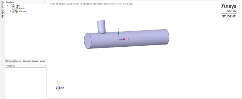
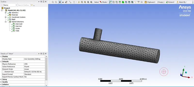
- Short Mixing Tee
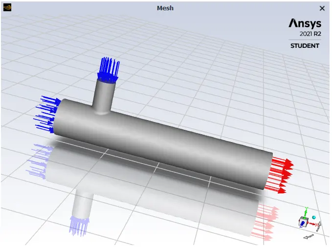
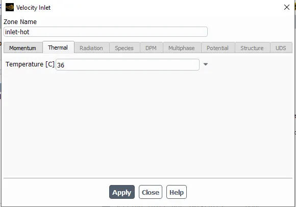
- Hot Inlet Temperature at `36^oC`
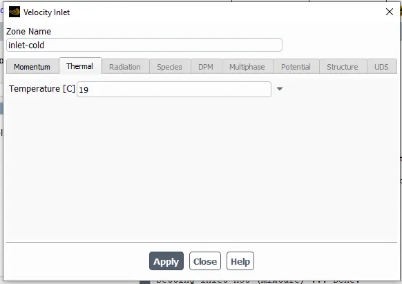
- Cold Inlet temperature at `19^oC`
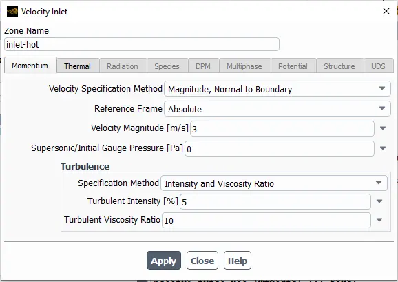
- Hot Inlet Velocity is 3 m/s.
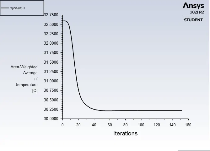
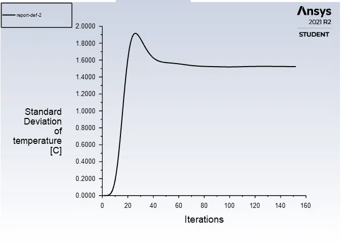
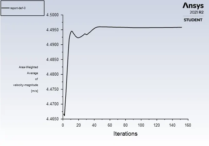
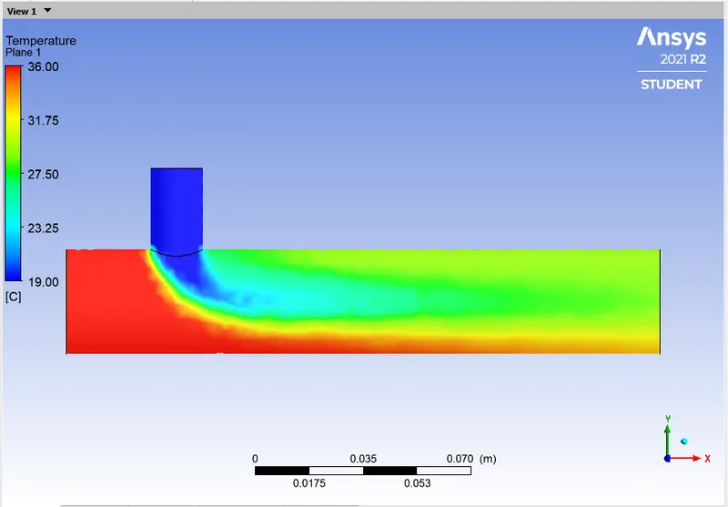
- Momentum Ratio = Velocity at cold inlet / Velocity at hot inlet = 2
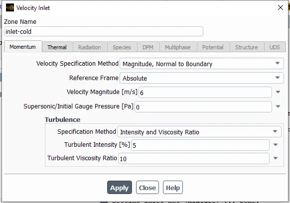
- Cold Inlet Velocity is (3*2) = 6m/s.
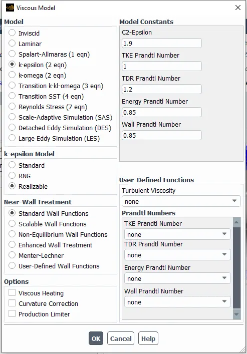
- Turbulence model is 'K-Epsilon Realizable' model.
GEOMETRY:
MESH:
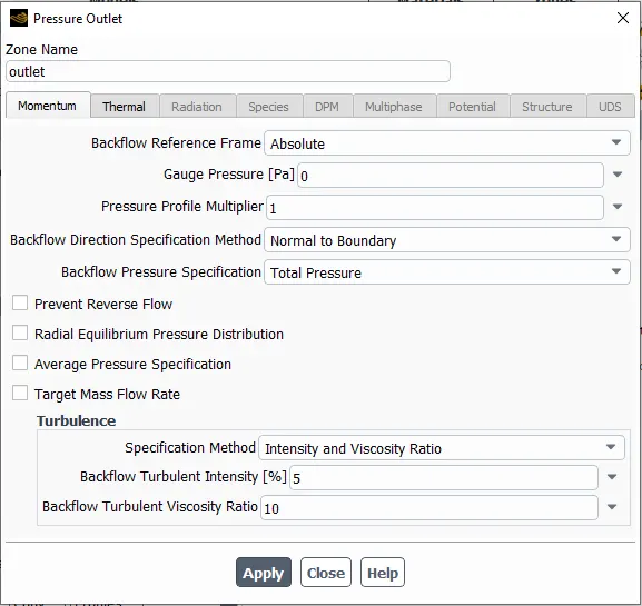
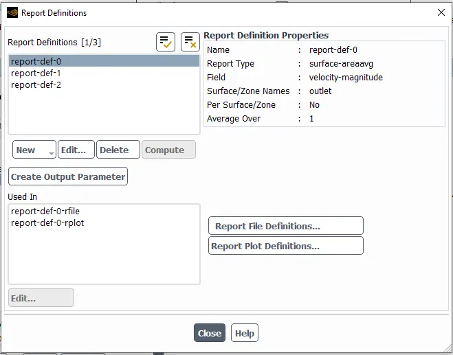
SETUP:
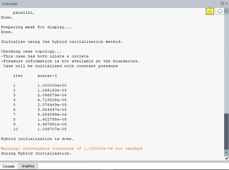
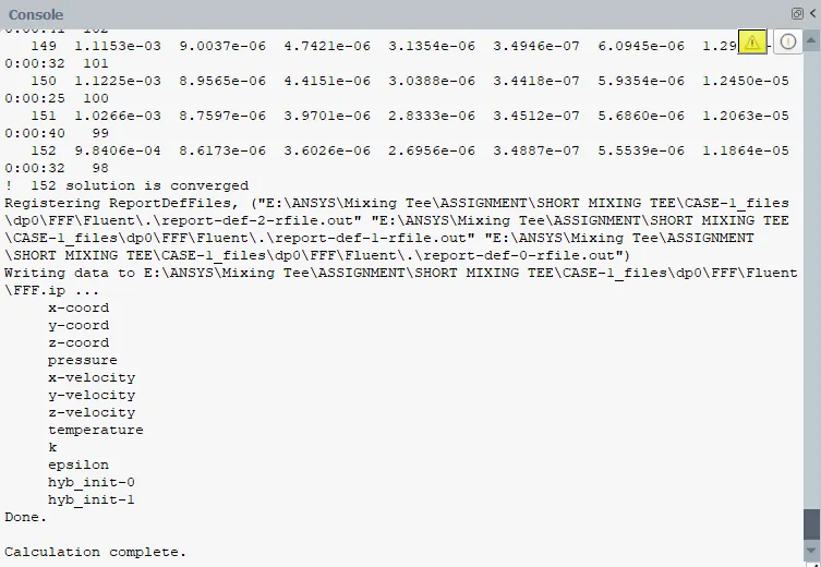
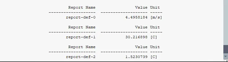
RESULTS:
LINE PLOTS:
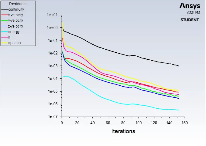
1. RESIDUALS:
TEMPERATURE:
STANDARD DEVIATION:
VELOCITY MAGNITUDE:
CONTOUR PLOTS:
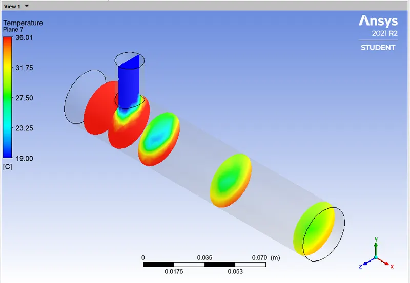
TEMPERATURE:
ALONG THE PIPE:
ACROSS THE PIPE:
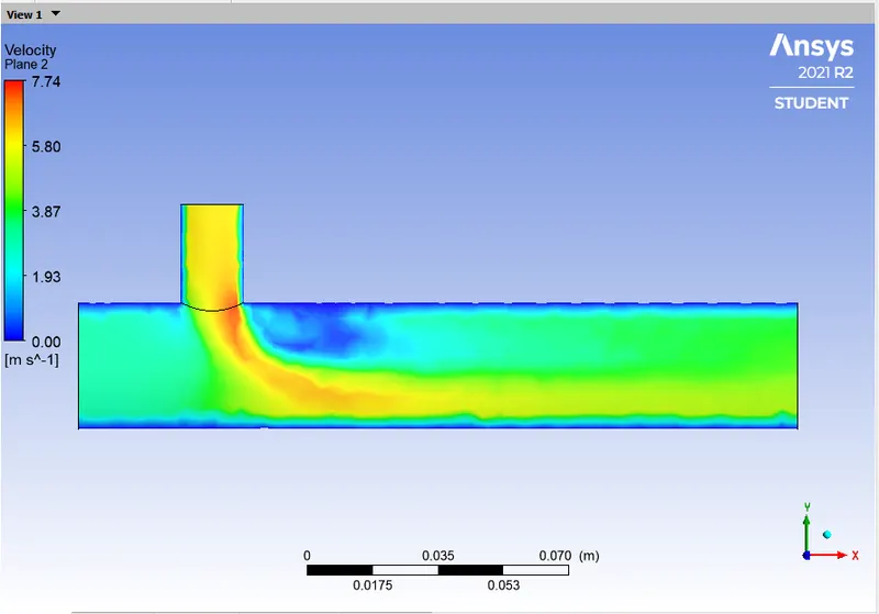
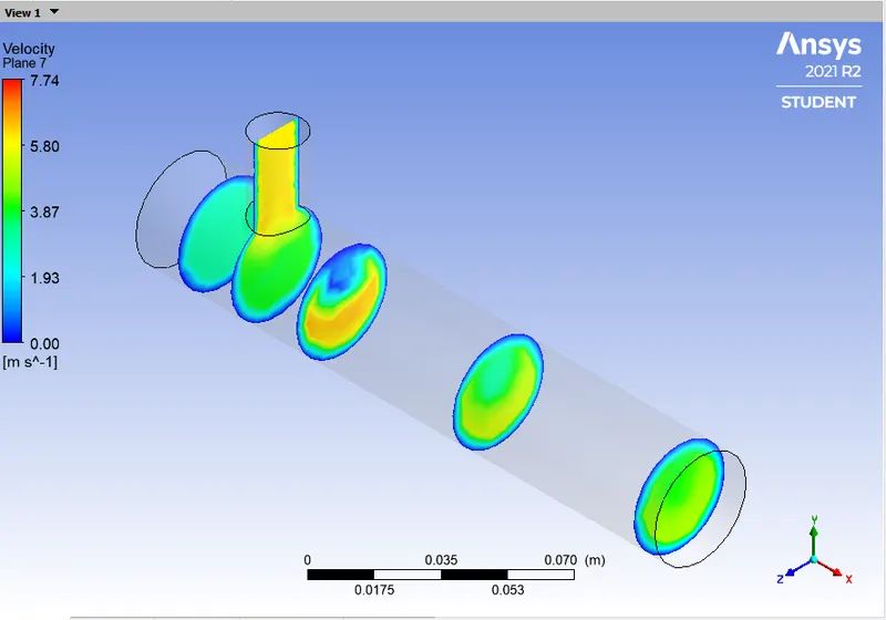
VELOCITY MAGNITUDE:
ALONG THE PIPE:
ACROSS THE PIPE:
SUB CASE 1.2
- Short Mixing Tee
- Hot Inlet Temperature at `36^oC`
- Cold Inlet temperature at `19^oC`
- Hot Inlet Velocity is 3 m/s.
- Momentum Ratio = Velocity at cold inlet / Velocity at hot inlet = 4
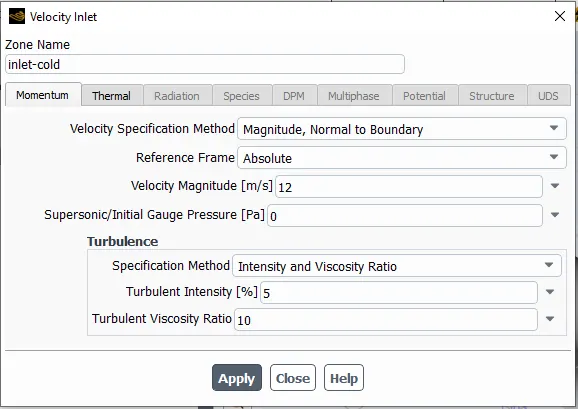
- Cold Inlet Velocity is (3*4) = 12m/s.
- Turbulence model is 'K-Epsilon Realizable' model.
GEOMETRY:
MESH:
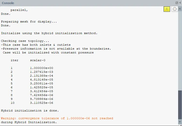
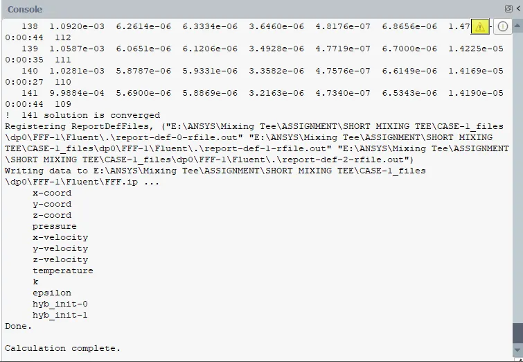
SETUP:

RESULTS:
LINE PLOTS:
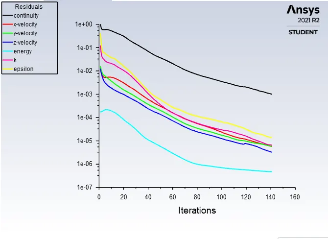
RESIDUALS:
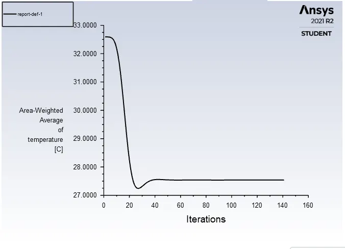
TEMPERATURE:
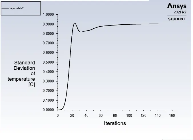
STANDARD DEVIATION:
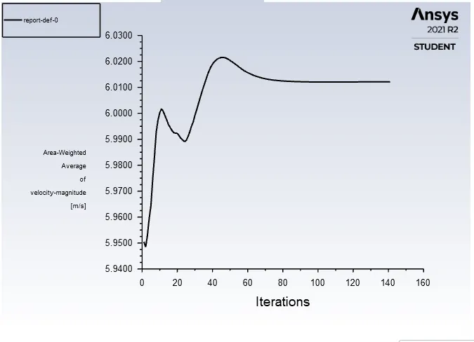
VELOCITY MAGNITUDE:
CONTOUR PLOTS:
TEMPERATURE:
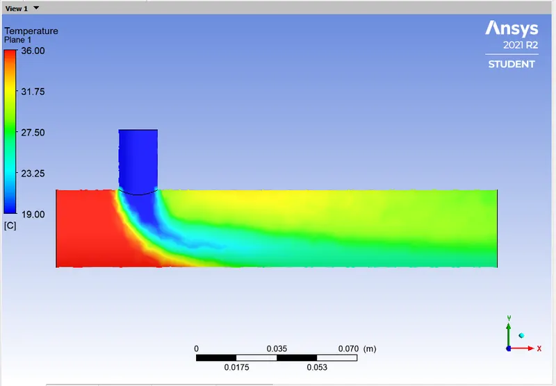
ALONG THE PIPE:
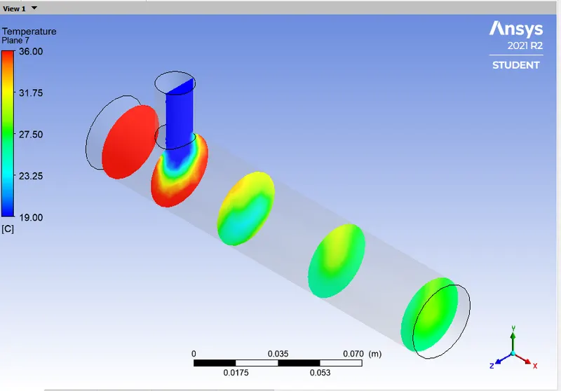
ACROSS THE PIPE:
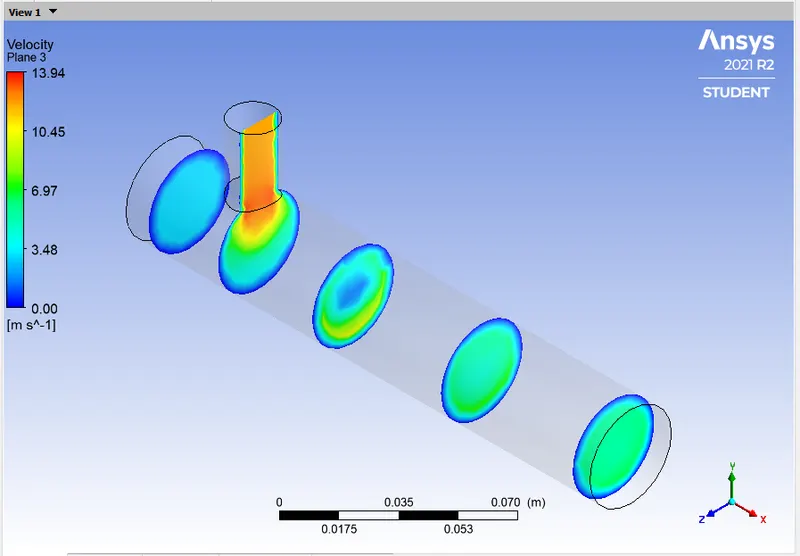
VELOCITY MAGNITUDE:
ALONG THE PIPE:
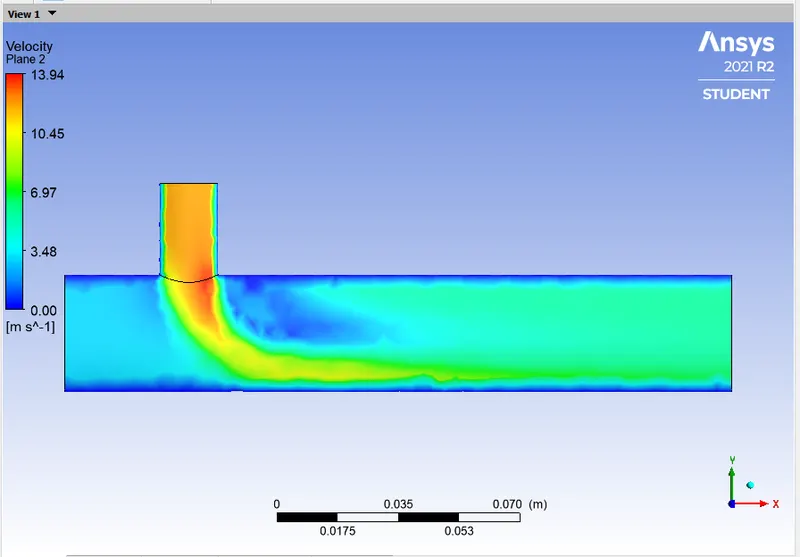
ACROSS THE PIPE:
SUB CASE 1.3
- Short Mixing Tee
- Hot Inlet Temperature at `36^oC`
- Cold Inlet temperature at `19^oC`
- Hot Inlet Velocity is 3 m/s.
- Momentum Ratio = Velocity at cold inlet / Velocity at hot inlet = 2
- Cold Inlet Velocity is (3*2) = 6m/s.
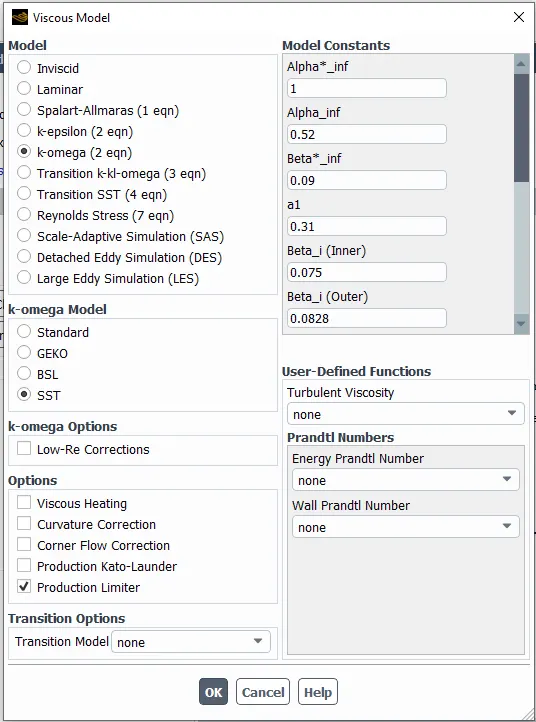
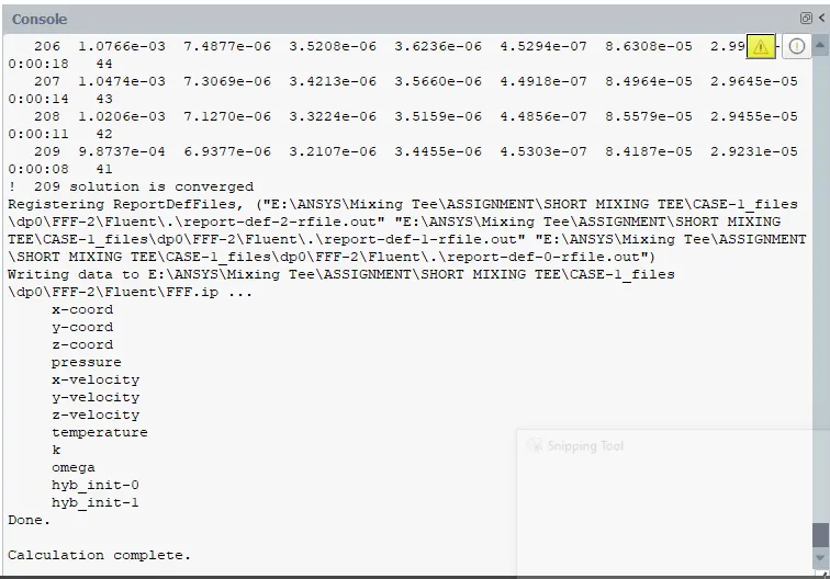
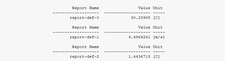
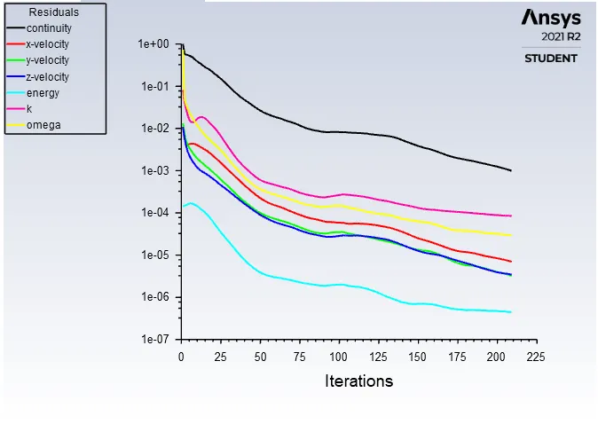
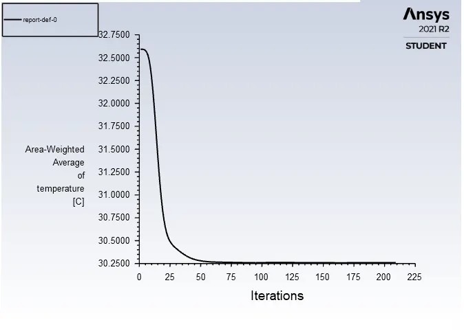
- Turbulence model is 'K-Omega SST' model.
GEOMETRY:
MESH:
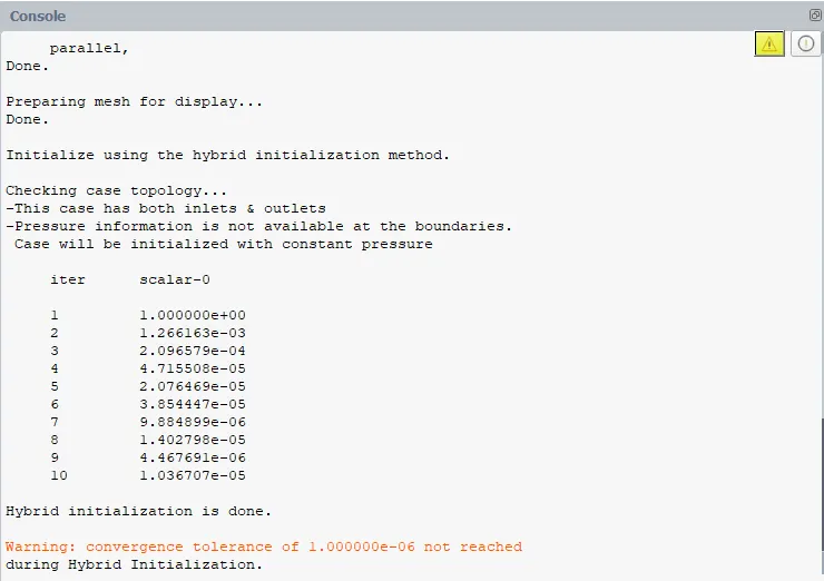
SETUP:
RESULTS:
LINE PLOTS:
RESIDUALS:
TEMPERATURE:
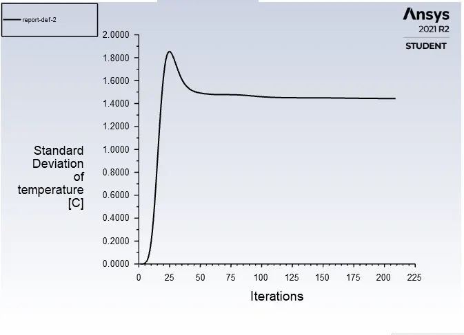
STANDARD DEVIATION:
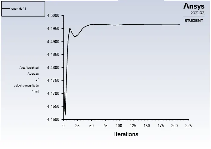
VELOCITY MAGNITUDE:
CONTOUR PLOTS:
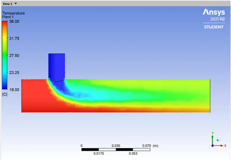
TEMPERATURE:
ALONG THE PIPE:
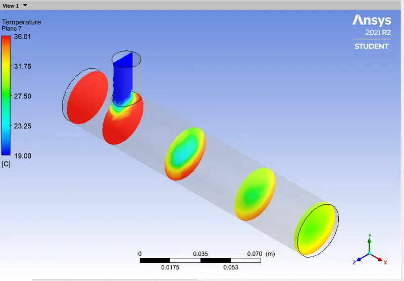
ACROSS THE PIPE:
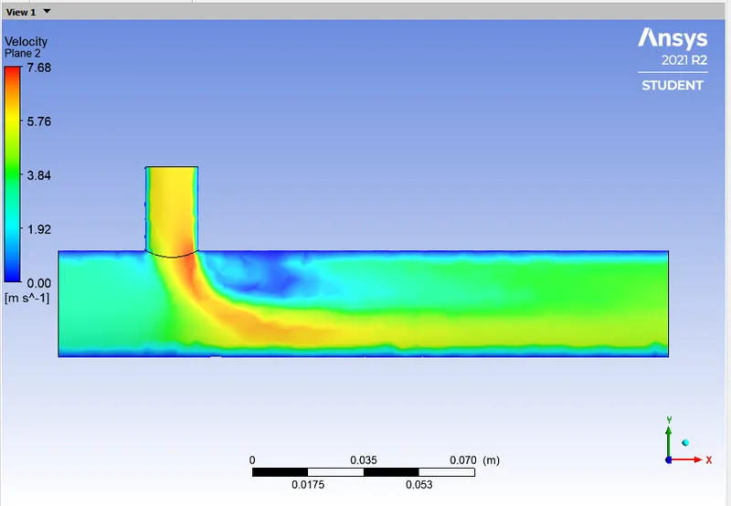
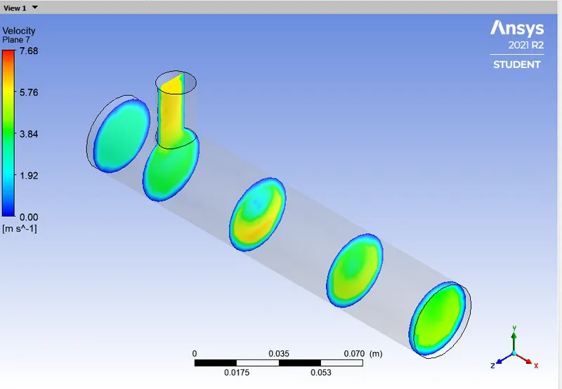
VELOCITY MAGNITUDE:
ALONG THE PIPE:
ACROSS THE PIPE:
SUB CASE 1.4
- Short Mixing Tee
- Hot Inlet Temperature at `36^oC`
- Cold Inlet temperature at `19^oC`
- Hot Inlet Velocity is 3 m/s.
- Momentum Ratio = Velocity at cold inlet / Velocity at hot inlet = 4
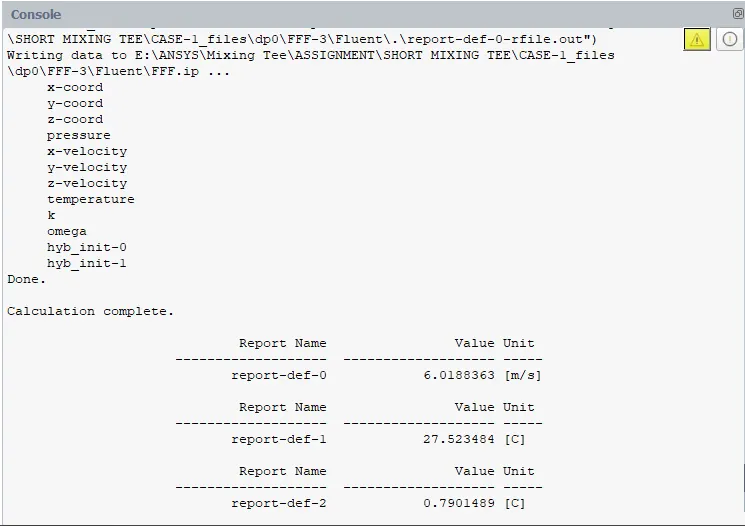
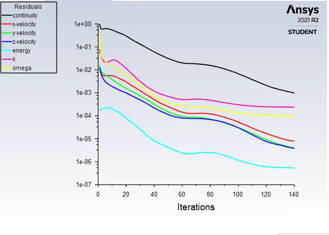
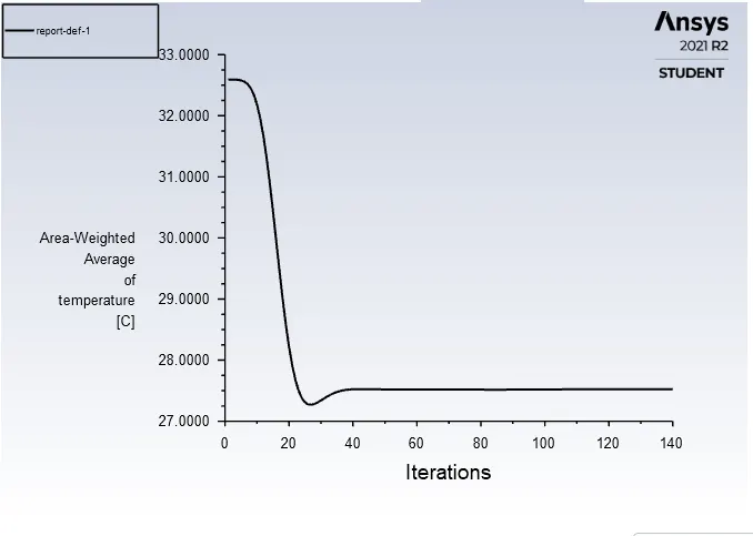
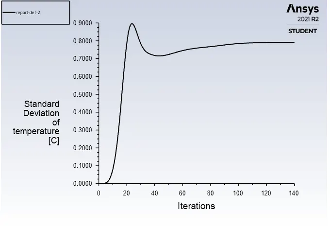
- Cold Inlet Velocity is (3*4) = 12m/s.
- Turbulence model is 'K-Omega SST' model.
GEOMETRY:
MESH:
SETUP:
RESULTS:
LINE PLOTS:
RESIDUALS:
TEMPERATURE:
STANDARD DEVIATION:
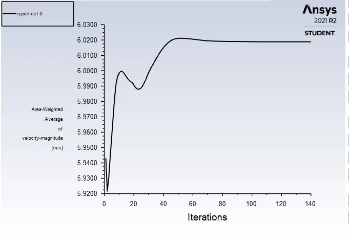
VELOCITY MAGNITUDE:
CONTOUR PLOTS:
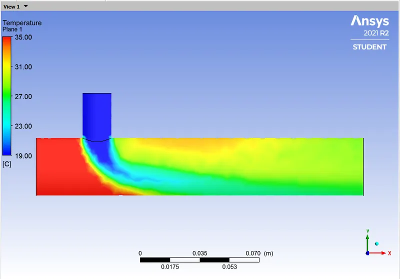
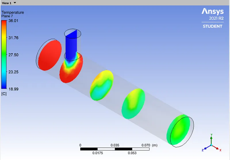
TEMPERATURE:
ALONG THE PIPE:
ACROSS THE PIPE:
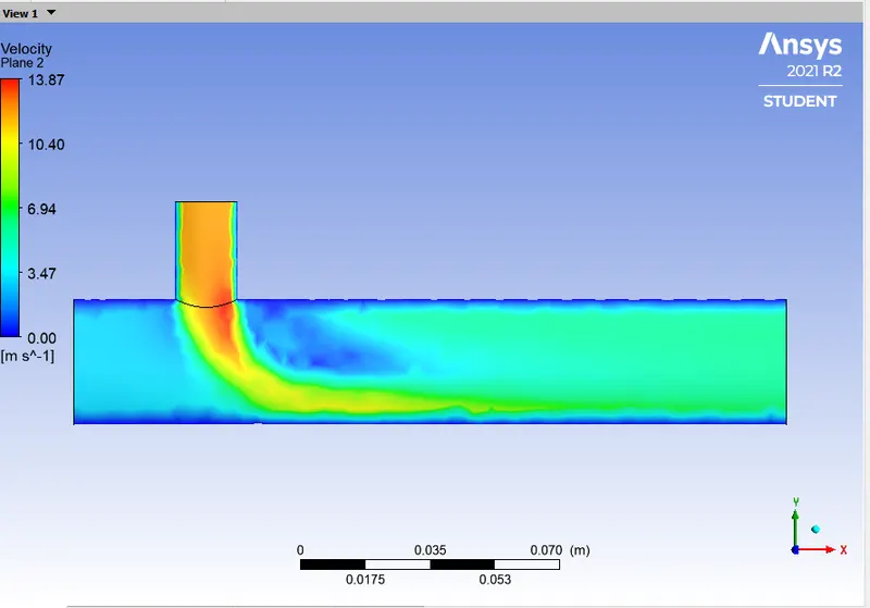
VELOCITY MAGNITUDE:
ALONG THE PIPE:
ACROSS THE PIPE:
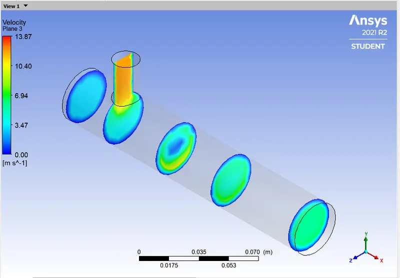
COMPARISION BETWEEN 'K-EPSILON' AND 'K-OMEGA' MODEL:
- K-Epsilon turbulence model is used for the formulation of the bulk motion of the fluid flow whereas K-Omega turbulence model is used for the formulation in the proximity of the walls.
-
K-epsilon (k-ε) turbulence model is the most common model used in computational fluid dynamics (CFD) to simulate mean flow characteristics for turbulent flow conditions. It is a two-equation model that gives a general description of turbulence by means of two transport equations (partial differential equations, PDEs). The original impetus for the K-epsilon model was to improve the mixing length models, as well as to find an alternative to algebraically prescribing turbulent length scales in moderate to high complexity flows.
- The first transported variable is the turbulent kinetic energy (k).
- The second transported variable is the rate of dissipation of turbulent kinetic energy (ε).
- The K–omega (k–ω) turbulence model is a common two-equation turbulence model, that is used as an approximation for the Reynolds Averaged Navier Stokes equation (RANS equations). The model attempts to predict turbulence by two partial differential equations for two variables, k and ω, with the first variable being the turbulence kinetic energy (k) while the second (ω) is the specific rate of dissipation (of the turbulence kinetic energy k into internal thermal energy).
- The K-Omega model is used when there are wall effects present within the case and also near the wall adverse pressure gradient is developed whereas the K-Epsilon is best suited for flow away from the wall like free surface flow region.
So as in this assignment we are not considering the wall effects on the flow and we are mainly concerned about the mixing effectiveness of the fluid we can use 'K-EPSILON' model for the next case having a long pipe.
CASE - 2:
SUB CASE 2.1
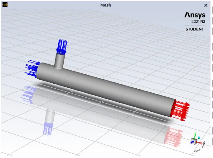
- Long Mixing Tee
- Hot Inlet Temperature at `36^oC`
- Cold Inlet temperature at `19^oC`
- Hot Inlet Velocity is 3 m/s.
- Momentum Ratio = Velocity at cold inlet / Velocity at hot inlet = 2
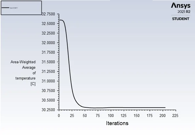
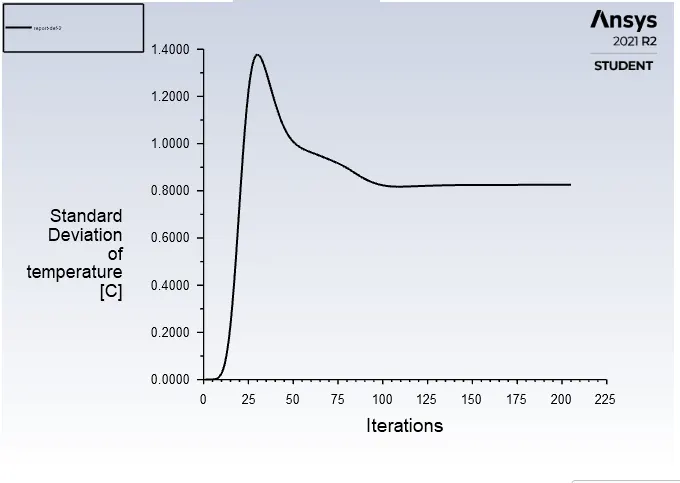
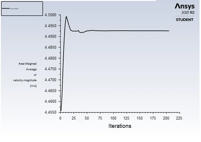
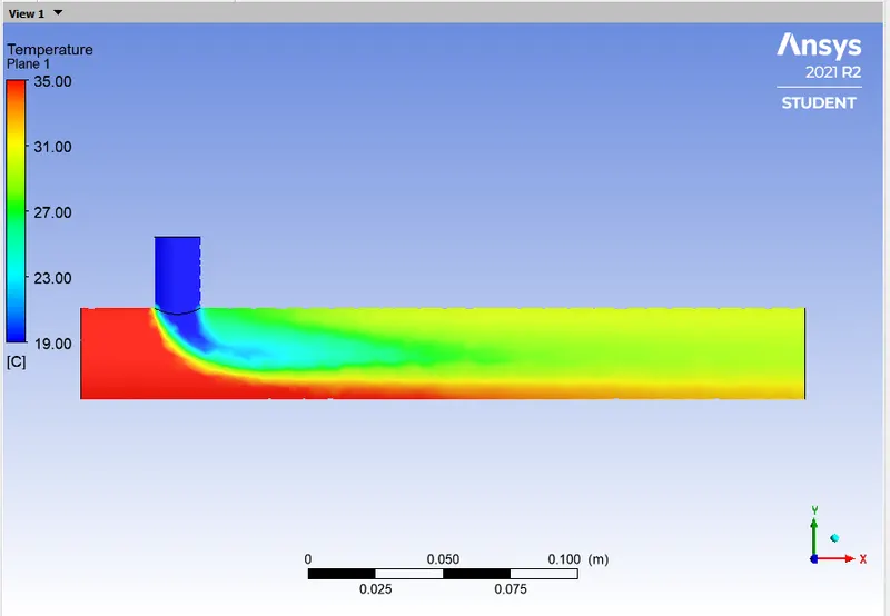
- Cold Inlet Velocity is (3*2) = 6m/s.
- Turbulence model is 'K-Epsilon Realizable' model.
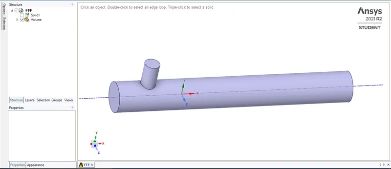
GEOMETRY:
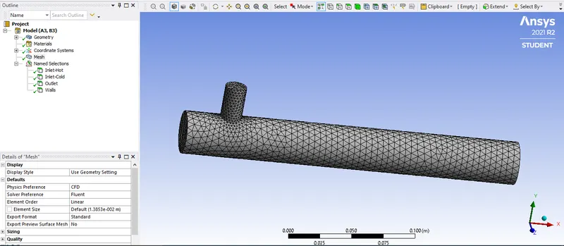
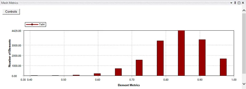
MESH:
SETUP:

RESULTS:
LINE PLOTS:
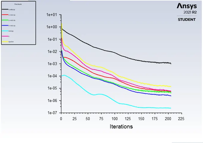
RESIDUALS:
TEMPERATURE:
STANDARD DEVIATION:
VELOCITY MAGNITUDE:
CONTOUR PLOTS:
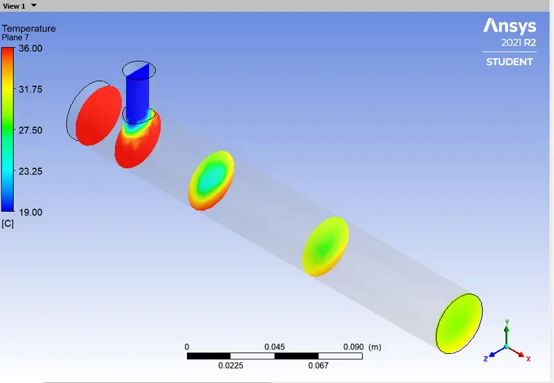
TEMPERATURE:
ALONG THE PIPE:
ACROSS THE PIPE:
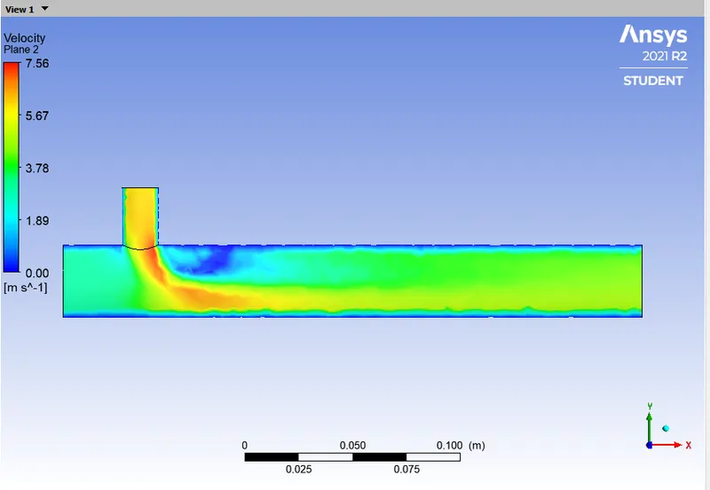
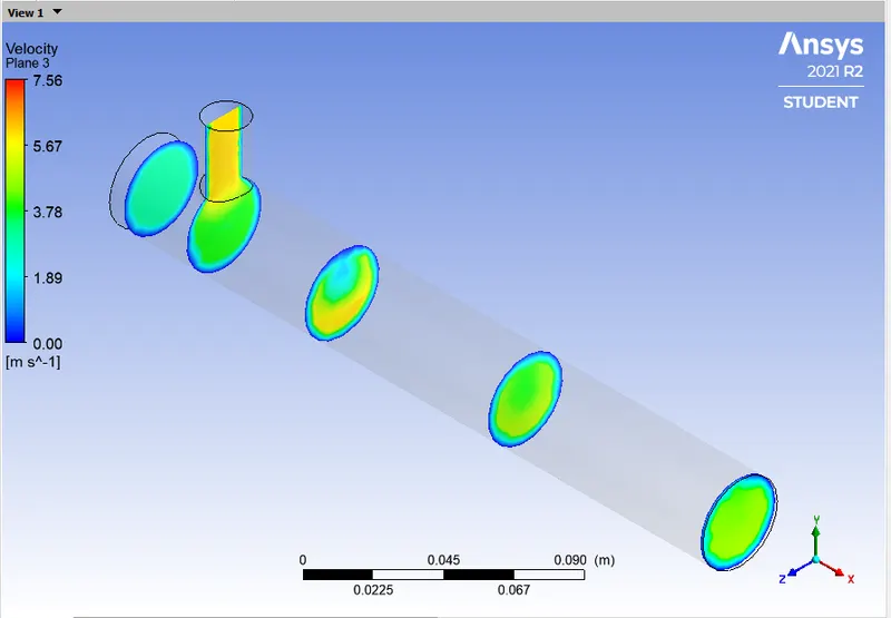
VELOCITY MAGNITUDE:
ALONG THE PIPE:
ACROSS THE PIPE:
SUB CASE 2.2
- Long Mixing Tee
- Hot Inlet Temperature at `36^oC`
- Cold Inlet temperature at `19^oC`
- Hot Inlet Velocity is 3 m/s.
- Momentum Ratio = Velocity at cold inlet / Velocity at hot inlet = 4
- Cold Inlet Velocity is (3*4) = 12m/s.
- Turbulence model is 'K-Epsilon Realizable' model.
GEOMETRY:
MESH:
SETUP:
RESULTS:
LINE PLOTS:
RESIDUALS:
TEMPERATURE:
STANDARD DEVIATION:
VELOCITY MAGNITUDE:
CONTOUR PLOTS:
TEMPERATURE:
ALONG THE PIPE:
ACROSS THE PIPE:
VELOCITY MAGNITUDE:
ALONG THE PIPE:
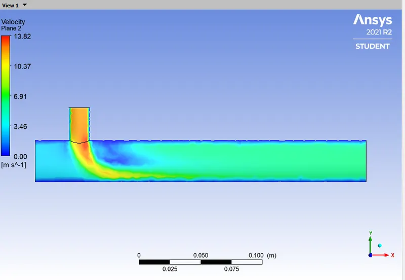
ACROSS THE PIPE:
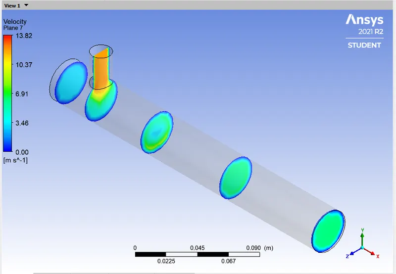
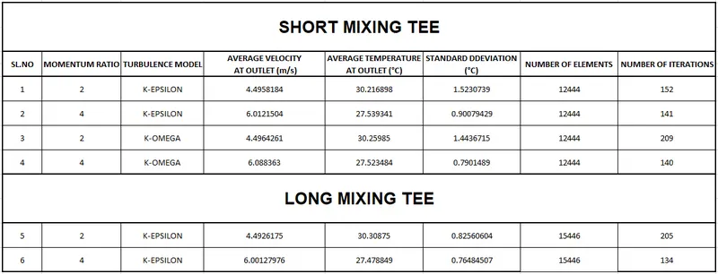
TABULATION:
GRID INDEPENCE TEST:
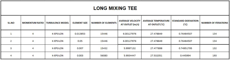
From the above it can be concluded that the case is Grid Independent.
CONCLUSION:
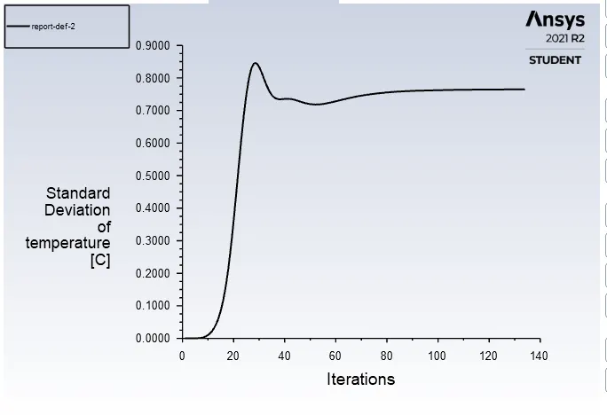
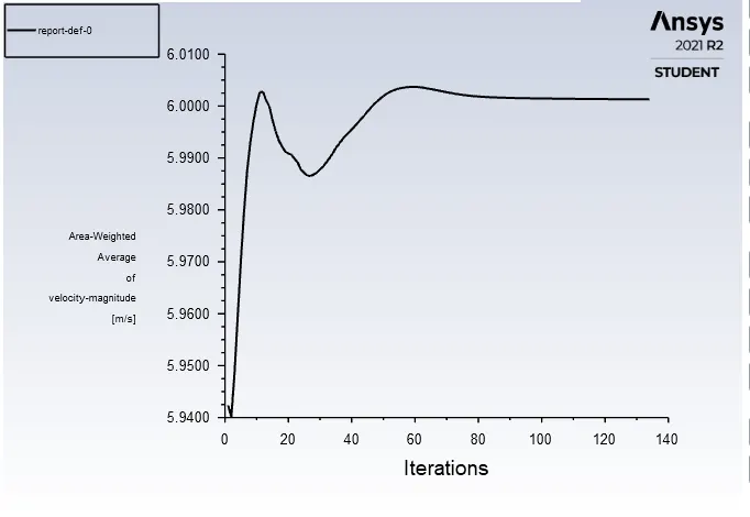
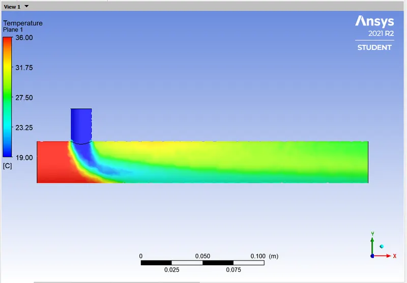
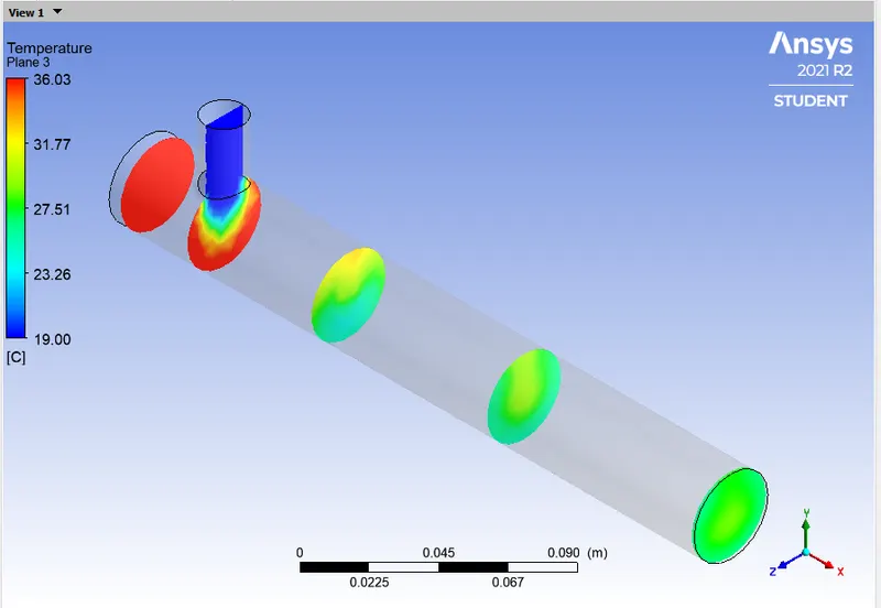
- From the above assignment it can be concluded that high momentum ratio or high velocity at cold inlet side gives better result and better mixing efficiency as compared to low inlet velocity.
- As the length of the pipe increases it gives slightly better mixing efficiency than the short pipe.
- So, for better mixing efficiency we must use a long pipe with higher momentum ratio or higher velocity at the cold inlet side.