Week 1:- Introduction to BiW and Fixtures Challenge
INTRODUCTION TO BIW AND FIXTURES
OBJECTIVE: The main objective of this challenge is to understand what is BIW and what is biw fixtures and their nomeclulature and to answer the questions asked in the challenge, to prepare a detailed report by attaching all the images wherever or whenever possible.
1. BIW & IT'S PARTS
- BIW stands for Body In White which is defined as the stage in automotive design or automotive manufacturing in which car body sheet metal components are been assembled by welding and by other joining process.
- It is also defined as the welded sheet metal component which form the vehicles structure to which the other component will be married. i.e engine, chasis, exterior and interior trims.
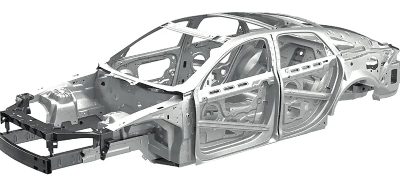
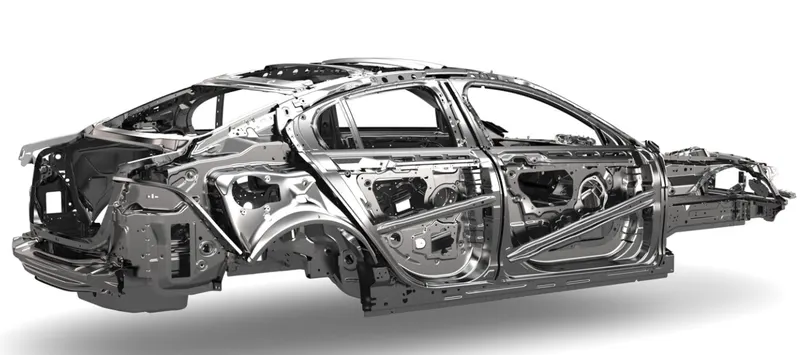
BIW PARTS
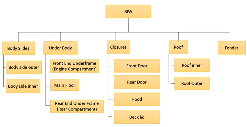
The biw parts are classified into
- BODY SIDES
- UNDER BODY
- CLOSURES
- ROOF
- FENDER
again the body sides are classified into two types they are
- body sides :- 1. Body Side Inner
2. Body Side Outer
Similarly the under body is also divided into three types they are
- UNDER BODY:- 1. Front End Under Frame (Engine Compartment)
2. Main Floor
3. Rear End Under Frame (Rear Compartment)
Then the closure is divided into four types they are
- CLOSURES :- 1.Front Door
2. Rear Door
3. Hood
4. Deck lid.
The roof is divided into two types
- Roof :- 1. Roof Inner
2. Roof Outer
The biw parts are classified as shown in below flowchart,
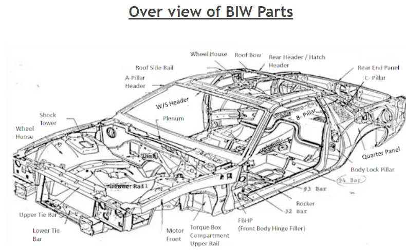
The various components of biw parts are as given in below figure,
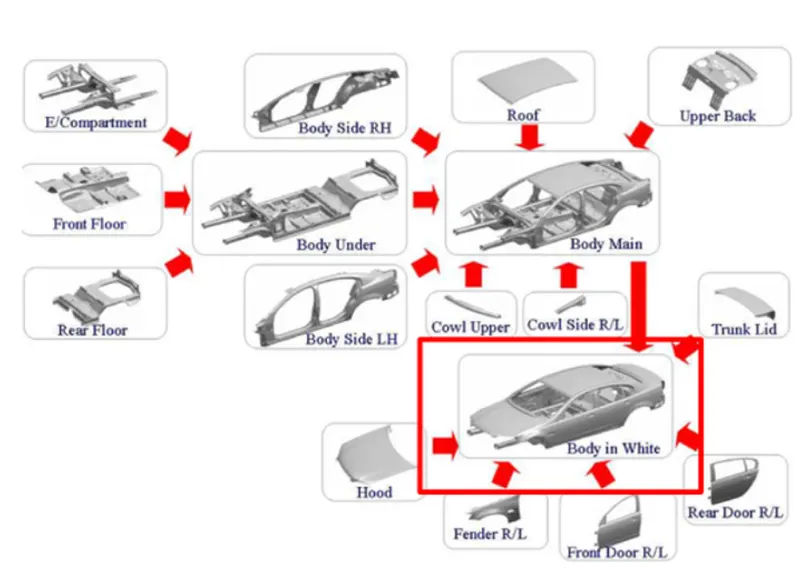
The overview of biw parts is given in the below figure,
2. BIW NOMENCLATURE:
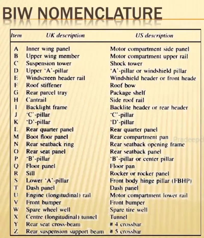
Nomenclature is the process of giving name to the systems or parts. The nomenclature of the same part will change from country to country, region to region.
The below image shows the nomenclature of of body in white,
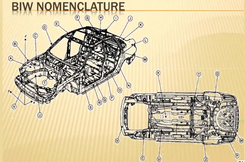
The names of the parts in UK and US are given in below image
3. FIXTURES & TYPES OF FIXTURES:
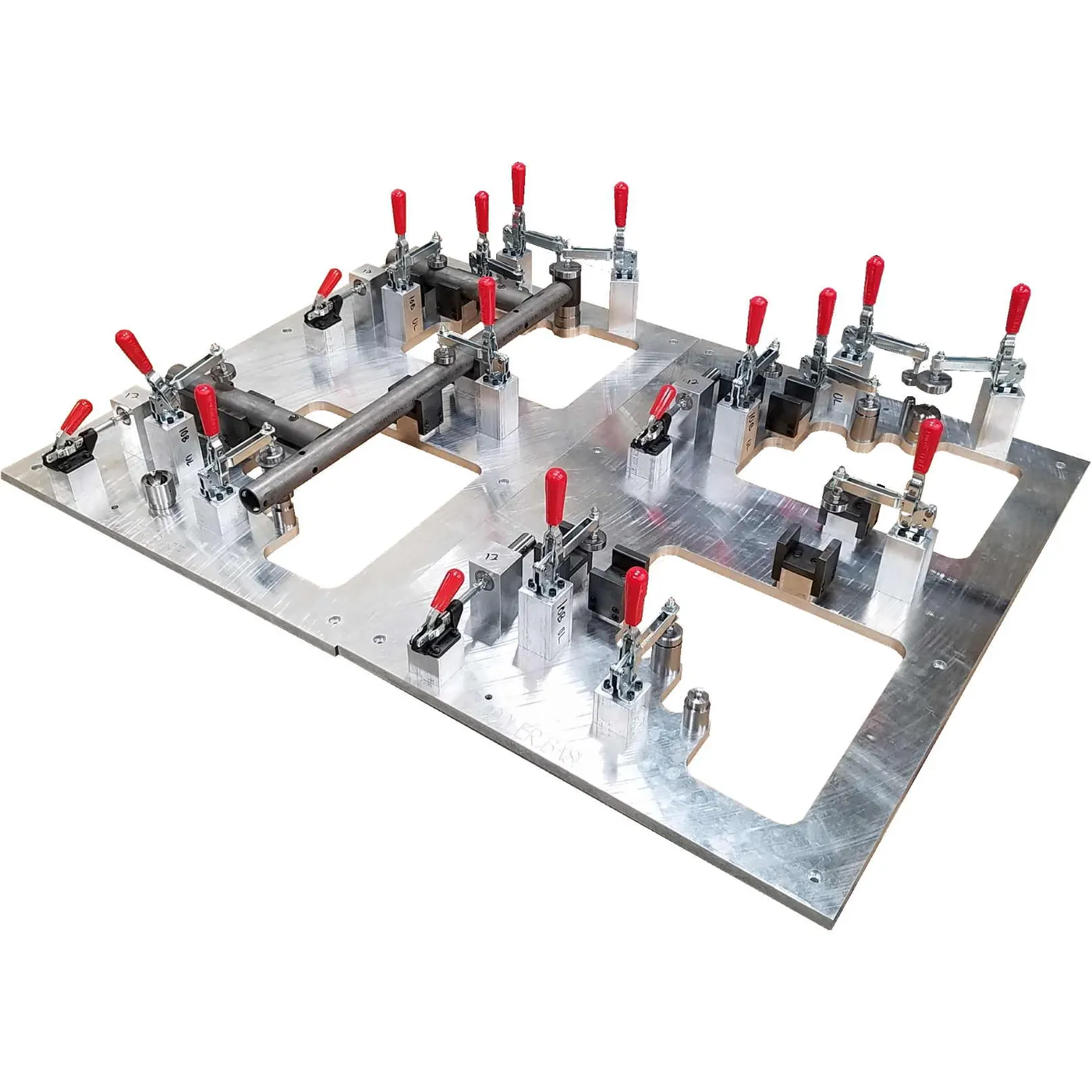
DEF: A fixture is a device which holds the work piece to be processed (welded), by using 3-2-1 principle.
In general a welding fixture consists of number of units together to hold the car panel, and is mounted on a base unit.
Welding fixtures are normally designed to hold and support the various components (work pieces) to be welded. it is necessary to support them in a proper location which is capable of preventing distortion in work pieces during welding. For this the locating elements need to be placed carefully. Clamping has to be light but firm, placement of clamping elements has to be clear of the welding area and the fixture has to be quite stable and rigid to withstand the welding stresses.
Simply, A fixture is a device which holds and locates a workpiece during an inspection or for a manufacturing operation. The fixture does not guide the tool where as a jig can guide the tool also.
The below image shows the welding fixture,
TYPES OF FIXTURES
The fixtures are mainly divided into three categories, they are
- PRODUCTION FIXTURES
- PRE PRODUCTION FIXTURES
- CHECKING FIXTURES
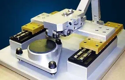
PRODUCTION FIXTURES: The producton fixture as the name suggest is used for mass production purpose and it is the fixture from where the car body is assembled and goes to the end customer. In case of production fixture, the material used for fixture and dimenssions and tolerance of the fixtures and the hardness of the fixture should be maintained and checked properly. Since it is used in mass production the design fixture should be in such a way that it is easily accessible and maintanable so that he can disassemble and assemble the fixture quickly without taking much time.
PRE PRODUCTION FIXTURES: This fixture is generally designed as a prototype fixture for initial batch production to study the feasibility and to make any improvements needed to the production fixture. So this is the base for the production fixture that set benchmark in criteria and help us to rectify the errors that we get from pre production fxtures before going to production fixture. Here the involvement of manual operators and engineers and quality and it will have larger cycle times then the production fixture.
In general we don't create a pre production fixture before prodction fixture because it is more time consuming and the cost of the product will become higher.
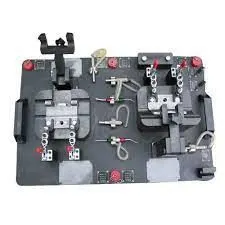
CHECKING FIXTURE: Checking fixture as the name suggests if is used for car panel geomentric inspection purpose. The checking fixtures are very similar to the geo fixtures but the difference is here no operations are performed where as in geo fixtures several operations are performed on workpiece.
4. BASIC PRINCIPLE OF FIXTURE DESIGN:
For a fixture designer, the major portion of design time is spent deciding how to locate thw work piece in the fixture.
Any rectangular body many have three axis along x-axis, y-axis and z-axis. It can more along any of these axes or any of its movement can be released to these three axes. At the same time the body can also rotate about these axes too. So total degree of freedom of the body along which it can move is six. For processing the body it is required to restrain all the degree of freedom (DOF) by arranging suitable locating points and then clamping it in a fixed and required position. The basic principle used to locate the points is explained below.
The degrees of freedom of body are given below
1. A body can translate along positive direction and negative direction of X- axis, Y- axis, Z-axis. So from here we have six degrees of freedom. and this six movements are called translation movements.
2. similar to the above statment a body in space can rotate along the three axis so that we can have another six movements and they are called as rotational movements.
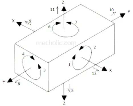
To be make th body stable now we have to arrest these 12 degrees of freedom. This can be done by using 3-2-1 principle and it is alos called as six point principle.
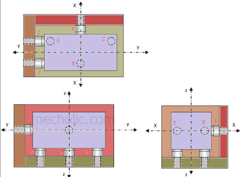
Pins A, B, C on the base plane ( a plane parallel to the plane which contains X and Y axis) restrict the rotation of component about X axis and Y axis. It also limit the downward movement of component along z axis. Ie. 1,2,3,4 and 5 degrees of freedom is restricted.
Pins D, E is in plane parallel to the plane containing X and Z axes. It prevents the rotation of component about Z axis (6, 7 degree of freedom) and the movement of the body in along Y axis towards one direction (8 degree of freedom).
The last pin F is in a plane parallel to plane contains Y and Z axes. It restricts the movement component along X axis in one direction.
Three remaining degree of freedom 10, 11, 12 is unrestricted. It facilitates the loading of the component in the fixture. This three degree of freedom may restrict after loading of component by using clamping devices.
5.BIW STATIONS:
In general BIW stations are divided into four sub stations, they are
- TOOLS STATION
- GRIPPERS STATION
- STANDS STATION
- MISCELLANEOUS
TOOL STATIONS: A tool is a fixture which consists of number of units togehter to hold a car part in general. This tool station is again sub divided into four major types they are
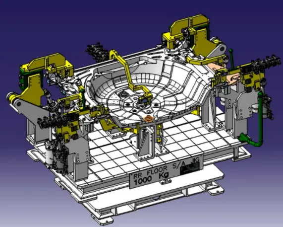
- GEO TOOL STATION: A geo tool is a fixture in which the geomentry of the panels whichare welded together is defined accurately. The pin tolerance for a geo pin will be of closer tolerance i.e -0.15 mm in general.
for example, consider a panel hole of size 20 mm, the pin diameter should be 19.85 mm.
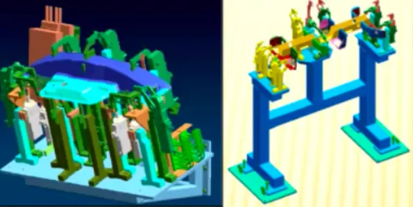
- RE- SPOT TOOL STATION: A re-spot tool is a fixture in which the remaining weld spots which are not achieved in geo-tool are welded for the pre welded panel from the geo tool. The pin tolerance for a re-spot pin will be of tolerance with -0.28 mm in general.
for example consider a panel hole of size 20 mm, the pin diameter should be 19.72 mm.
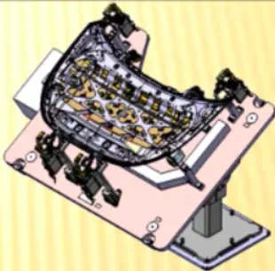
- MARRIAGE OR HEMMING TOOL: A marriage or a hemming tool is a fixture in which the inner panel assembly an outer panel assembly are joined together. These are done by welding or hemming in case of closure panels.
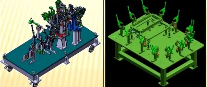
- CHECKING STATIONS: A checking station tool is a fixture which is used to check the automobile parts or assemblies, ensuring the cordinates, relative dimenssions and positions as per the tolerances. A checking station can be a guage type, fixed type and automated checking fixture.
GRIPPER STATIONS: A gripper is a device or a fixture which holds the car panel, and is fixed to the manipulating end of a robot or an end effector. it is alos known as EOAT- End Of Arm Tooling.
TYPES OF GRIPPERS:
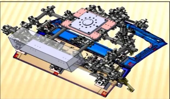
- Material Handling Gripper: Material handling grippers are designed to handle the car panel from one tool to another tool which means from one station to another station.
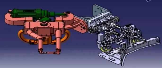
- process Gripper: Process grippers are designed to handle the car panel from one tool to other tool, and in addition to that it under goes process like pedestal welding, pedestal riveting, gluing, sealing, etc.,
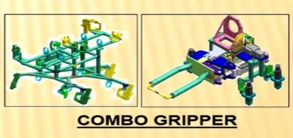
- Combo Gripper: Combo grippers are designed for handling the car panel from one tool to other tool, also with combination of weld gun at another side of the gripper for welding
Combo gripper= Gripper+ Weld Gun.
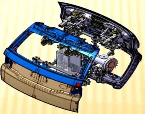
- Dual Gripper: Dual grippers are designed for handling the car panel from one station to another station, with two sided gripper.
Dual Gripper= Gripper+Gripper.
STAND STATIONS: The different types of stand stations are given below
- Gluing and sealer stand: Gluing gun or sealer gun is fixed to a welded or a standard stad which is grouted to the floor permenantly.
- Docking stand: When robots are selected for multi tasking like material handling & welding, which cannot carry both due to some limitations (pay load capacity of the robot or space constraint). The robot will drop and pick the gripper or gun after completing the respective operations with the help of docking stand.
- Date stamp stand: The panel will get the date embossed on to it, with the date stamping device mounted on this date stamp stand.
MISCELLANEOUS STATIONS AND TYPES:
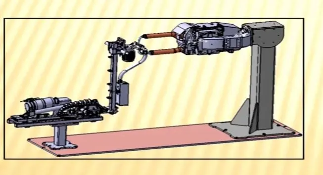
- Pedestal gun stand: Weld gun is mounted to a fixed stand which is grouted to the floor permanently, where the process gripper carries the car panel to weld the spot with this fixed weld gun.
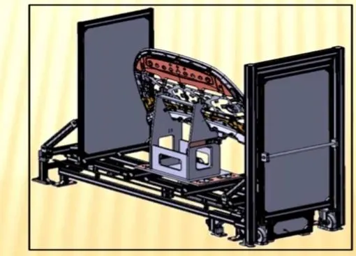
- Take Out Trolley: Take out trolley is used to take the car panel out of the robotic working cell between the cycle for the inspection purpose.
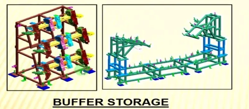
- Buffer Strage stand: This is to store the things in the iventory while the machine is under maintance or when the production stops due to extrenal reasons.
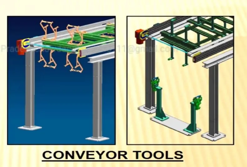
- Conveyer tool stand: This stand is used to trasport the panels from one tool to another tool or from one station to another station by means conveyors. They might belts or chains.
6. BASIC TERMINOLOGY USED IN BIW FIXTURES:
1. MYLAR:
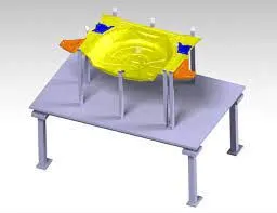
MYLAR is one kind of block that touches the panel and holds or clamps the panel. Mylars are always designed in CAR LINE. Mylar is also called NC(Numerically Controlled)Block. Mylars are mounted on any block or plate with Shimming, So that height of mylar can be adjusted accordingly at the assembly level. For ‘A’ class surfaces Nylon mylars are used. So that surface can be saved from scratches.
Shimming can be 1 directional, 2 directional, or 3 directional as per the NC cut.
The part which is mounted on the base plate and holds a clamp or pin cylinder on it, is called Riser. Riser can be Standard Part or manufactured part, it varies from project to project. A riser can be a Single part or welded part. Standard risers also have various shapes and sizes.

In automotive design, a class A surface is any of a set of freform surfaces of high efficiency and quality. Although, strictly, it is nothing more than saying the surfaces have curvature and tangency alignment – to ideal aesthetical reflection quality, many people interpret class A surfaces to have G2 (or even G3) curvature continuity to one another.
Class A surfacing is done using computer aided design applications. Class A surface modellers are also called "digital sculptors" in the industry. Industrial designersdevelop their design styling through the A-Surface, the physical surface the end user can feel, touch, see etc.
15.REED SWITCHES:
A reed switch is an electromagnetic switch used to control the flow of electricity in a circuit. They are made from two or more ferrous reeds encased within a small glass tube-like envelope, which become magnetised and move together or separate when a magnetic field is moved towards the switch.
16. SENSORS: A sensor is a device that detects and responds to some type of input from the physical environment. The specific input could be light, heat, motion, moisture, pressure, or any one of a great number of other environmental phenomena.
CONCLUSSION