Week 1:- Introduction to BiW and Fixtures Challenge
- What is BIW & define its parts?
Answer
BIW
- BIW fixture means the stage of an automotive Design or Automobile Manufacturing .in which the car body sheet metal component are been assembled by welding and other joining processes
- BIW refers to the welded sheet metal component which from the vehicles a structure to which the other component will be married i.e engine, chassis exterior, and interior trims.
- Body in white or BIW refers to the stage in automobile design or automobile manufacturing. in which the car body sheet metal (includes doors, Hoods, and deck lids) has been assembled or designed but before the component (chassis motor) and trims (Wind-shield, seats, upholstery, electronics, etc) have been added.
- In today's situation, automotive BIW is made of steel (various steel grade material -DP, DD, HDP, etc.) as well as made aluminum alloy (e.g., AUDI A8)
- All the Interior Parts (Commonly used in Automotive) e.g. Dashboard, Trim (Door Trim, Pillar Trims, Roof liner, Seats are mounted on the BIW shell with the help of various brackets or nuts mounted on the BIW.
- Exterior (Commonly used term in the car industry) components e.g., Front Bumper, Rear Bumper, Fender LH/RH, Side Mirrors are mounted on the BIW shell with the help of various brackets or mounting systems.
- To achieve an efficient car design it is necessary to have the BIW design with optimized mass
- BIW design also needs to be lightweight structure so that there will be a possibility of reducing the weight of the vehicle weight so that we can reduce the consumption of fuel and increase the performance of the vehicle.
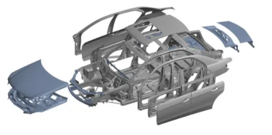
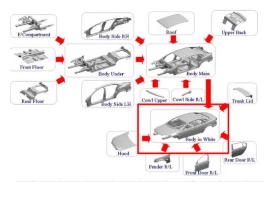
Figure-1 Exploded View of BIW Component
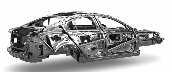
Figure-2 BIW Component
Major Influencing Factors of the BIW Design
- Number of Parts
- Material
- Internal structure Reinforcements.
Requirements of BIW structure:
- Comfortable space
- Strength & stiffness
- Low weight material
- Corrosion-resistant
- Aerodynamic & good appealing structure: BIW joinery defines the exterior and interior look.
- Sufficient space for packaging and provisions made for inner trim and aggregates
- Pedestrian and occupant protection during a roll-over accident
- Structure should support
- All interior parts like dashboard, trims, seats, etc.
- All exterior components like the front bumper, rear bumper, fenders, mirrors, etc. are mounted on the structure in means of mounting brackets and nuts on the BIW
There are two types of Bodies structure are using in BIW
- Monocoque Body structure
- Frame Mounting Body Structure
1.Monocoque Body Structure
In this type of structure, all the members of the body are load carrying and they are integrated. Here chassis is inbuilt with the BIW itself and there is no separate chassis. Wheels are directly mounted to the BIW with the help of a suspension system. Used in all the passenger cars and to some extent in utility vehicles.
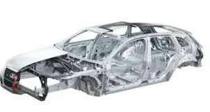
Figure-3 Monocoque Body Structure
2. Frame Mounting Body Structure
In this type of body construction, the body is placed on the frame which is the major load-carrying member. The body is mounted on a separate chassis/frame and the wheels are mounted on the chassis and not to the body. Used in utility vehicles, trucks, buses.
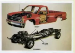
Figure-3 Frame Mounting Body Structure
BIW Parts
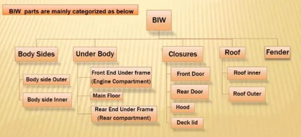
Figure-4 Classification of BIW Parts
BIW Structure is Divided into the following Sub-Structures: -
- Under Body Structure
- Front End Structure
- Body Side Structure
- Closures
- Roof
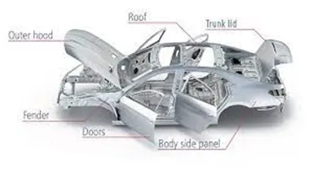
Figure-5 BIW Part
All the sub-structure consist of the following major panels
Under Body Structure
- Das panel – provides a partition between engine and cabin
- FRT floor – Provides a base for the seat
- Raiser – connects front floor to the rear by providing levels difference
- Rare floor – Floor on the rare of the car and provides partition from ground and base for the rear seats
- Rear wheelhouse
Front End structure
- Plenum Panel – A chamber location Between the throttle body and runner of the intake manifold
- FRT Wheelhouse (fender)- It is an encasement around the front wheel
- Wine Panel – Outermost side panel in the front
- Cowl - portion of the body boundary by the front fenders, the bae of the windshield, and the rear edge of the hood.
- Upper tie bar - upper panel in the front connecting the two sides of the front structure
- Lower tie Bar – Lower panel in the front connecting the two sides of the front structure
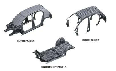
Figure-6 Outer panels, Inner panels, Underbody panel
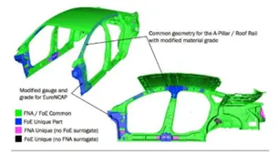
Figure-7 Upper Body
Body Side Structure:-
- A-Pillar - Front most support to the roof
- B-Pillar - second support to the roof
- C- the pillar – C-is rare most support to the roof in case of two-row seating system it will be the third one.
- D-pillar – D-is the fourth support usually rare-side of the quarter panel.
- Ring Panel – A structured panel connecting the rare and front portion
- Quarter panel – Rare most panels of a bodyside structure
- Drip Rail / Gutters – An exposed channel applied to the roof over the side window to direct water away from the windows
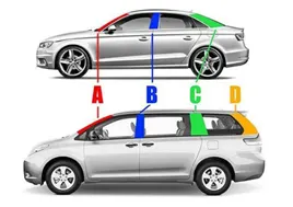
Figure-8 Classifications of Pillars
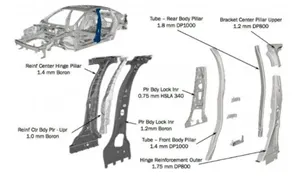
Figure-9 B-pillar Design with detailed structure
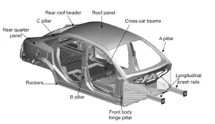
Figure-10 BIW parts including all pillars
Closures
- All Doors
- Hoods / Bonnet – A hinged panel providing access to the engine
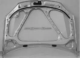
Figure-11 Hood
Roof Structure: -
- Roof
- Headers - Structure member above the wind-shield at a juncture with the forward edge of the roof panel
- Bows
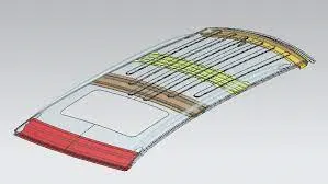
Figure-12 Roof
Reinforcement Components
The part which is used to support and provide stiffness and strength to other components of BIW is known as the Reinforcement component some of the reinforcement components are shown below image.
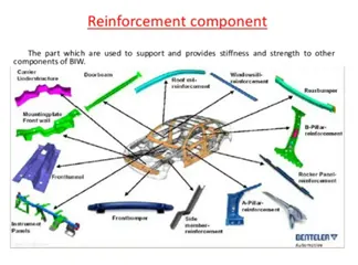
Figure-13 Reinforcement of component
Manufacturing of BIW Component
Stamping Die Design (Die Layout & Operations)
The BIW sheet panels are stamped into shapes by the mean of stamping dies the panel sheets are forms by applying various loads in the process with the help of press tools by achieving different sequences of operations the biw stamping parts are processed from blank
Here I have attached the different types of operations which is been used to get a final part of the sheet panel from a plain sheet/blank. Three different types of biw components are shown below to understand the different types of operations involved in the stamping process of BIW components.
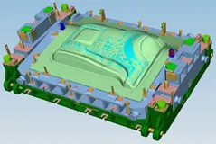
Figure-14 Stamping Die
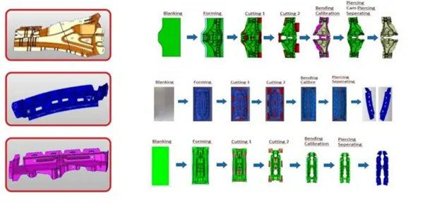
Figure-15 Different types of operations involved in the stamping process in BIW
Some of the basic operations are
- Blanking
- Forming
- Bending
- Drawing
- Piercing
- Cutting
- Deep Drawing
For these various operations, different types of press tools have been used which be designed by tool Designers and Manufacturing By Toolmakers.
In the Below Given Pictures, the process planning for stamping part/BIW parts is shown by mentioned the different operations which is been indicated by different colors.
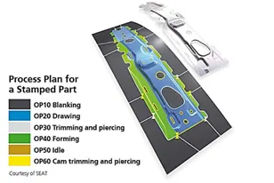
Figure-16 Process plan for stamping parts
In the below-given picture the sequence of operations which is been carried to complete the stamping BIW components from blanking operations to last stage operations
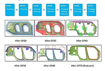
Figure-17 Sequence of operations during stamping
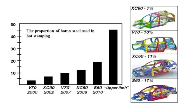
In recent years, automotive lightweight has led to the increasing demand for high-strength steel (HSS) auto parts. Lots of correlative companies and research institutes have invested a large amount of energy into the research of advanced automotive HSS forming technology. Though the advantage of HSS is a high strength, it still has some disadvantages such as the poor forming performance, the uncontrollable spring back, and ease to crack during the forming process. Therefore, it is difficult to realize the manufacture of complex auto parts by adopting traditional cold stamping technology, where hot stamping technology is needed.
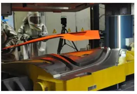
HSS hot stamping technology is a new manufacturing technology developing in recent years, which combines the traditional hot forging and cold stamping technology. It is a mode of production that integrates the stamping of steel under the condition of high temperature and forming and quenching indies. It is also known as Hot Forming, Hot Stamping, Hot Press, Press Hardening, or Die Quenching abroad. Hot stamping technology of HSS can be used to manufacture car structural components whose tensile strength is up to 1500 Mpa, such as the front bumper, tail bumper, A&B&C PILLAR, roof frame, underbody, door panel, and so on.
Hot Stamping Process
The hot stamping process is the necessary means to realize the product forming and strength increasing of hot stamping steel, and it is the indispensable premise for HSS of hot stamping to acquire high strength performance. Its typical technological process is: first, heat the sheet to a specific temperature range for customization and austenitize it completely, and then transfer it into the water cooling hot stamping dies for stamping and quenching, and finally realize the microstructure’s phase transformation and the increase of strength. According to the complexity of processing and the forming process of actual parts, the hot stamping process can be divided into directly hot stamping and indirectly hot stamping process.
- Direct hot stamping process:
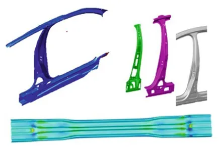
In the direct hot stamping process, a blank is heated up in a furnace, transferred to the press, and subsequently formed and quenched in the closed dies. Afterward, the product is trimmed by laser and finished through other follow-up processes. The advantages of the direct hot stamping process are as follows:
(1) The blank is formed and hardened in one mold, which saves the cost of performing and accelerates the pace of production.
(2) The blank is flat, which not only saves heating area and energy but also can be heated by a variety of heating methods, for example, induction heating.
The disadvantages of the hot stamping process are as follows: it cannot be used for forming automobile parts with complex shapes, and it needs laser cutting equipment. In addition, the design of a cooling system of molds is more complex. For automotive body structure, the parts with a simple shape, not necessary for deep drawing, can be manufactured by direct hot stampings, such as the inside and outside pieces of the b-pillar.
- The indirect hot stamping process
In the indirect hot stamping process, the sheet metal is performed by cold forming before it is heated to austenite temperature in a furnace. After being held for some time for full customization, it will be transferred into the hot stamping tools with a cooling system to be stamped and quenched at the same time. The indirect hot stamping process is also named “multi-step”. Compared to the cold stamping steel, though the flowability of the heated steel increases, the tensile strength would decrease accordingly, making it easy to crack for complex parts during the forming process. The indirect hot stamping process is the exact method invented to solve the problem and form complex BIW parts that may not be formed by the direct hot stamping process.
Compared to the direct hot stamping, the HSS sheet is uncoiled and cut according to the shape of the product, then performed by the traditional process such as cold forming process, flanging, punching and cutting-edge, and so on. After that, the preformed semi-finished product is transferred to the continuous furnace to be heated and insulated before it is sent to be formed and quenched. Afterward, the product will be trimmed by laser processing or other necessary follow-up processes according to the characteristics of the components, or directly output finished product.
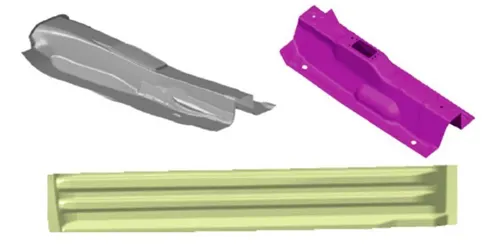
Figure-20 Parts produced by indirect hot stamping Technique
The advantages of the indirect hot stamping process are as follows:
(1) The parts with complex shapes and almost all of the current stamped carrying parts can be formed by the indirect hot stamping process.
(2) After the performing of the blank, it is unnecessary to worry about the forming performance of the blank at high temperature in the subsequent hot stamping process, which can ensure the martensite microstructure of the blank followed by complete quenching.
(3) The blank can be processed by trimming, flanging, punching, and other pro-
cessing after being performed so that it will be easier for processing after it is quenched. For example, the blank that is quenched must be trimmed by laser cutting equipment, which greatly increases the cost.
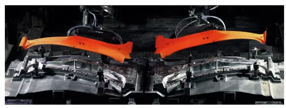
Figure-20 Continuous Ring Heating Furnace
The continuous ring heating furnace used in the hot stamping should ensure that the blank is heated up to the set temperature for a complete austenitization. At the same time, high-temperature oxidation and decarburization should be avoided for those blanks without anti-oxidation coating. The continuous ring heating furnace has its unique core technology in comparison with other heating furnaces, and its brief descriptions are as follows:
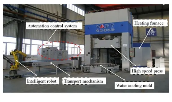
Figure-21 The hot stamping automatic production line
(1) Most of the automotive HSS blank is sheet. The sheet should be heated up to the specified temperature and then hold heat to be fully austenitized. Therefore, the temperature distribution in the heating furnace is required to be homogenous;
2) For the steel sheet without protective coating from oxidation, its oxidation and decarburization are very serious at elevated temperatures. Therefore, the furnace is needed to take strict measures of gas protection;
(3) All the parts of the heating furnace run under the conditions of long term and continuous operation at a high temperature (over 800 °C), so their expansion property, high-temperature fatigue, failure rate, and maintainability must be taken into consideration;
(4) Hot stamping production line needs to satisfy the setting cycle time, so it needs the equipment for loading or unloading which can meet the requirements for the high-temperature work and corresponding automatic control system;
(5) One of the purposes of the hot stamping technique is to save energy and protect the environment, thus it also requires an energy-efficient heating furnace.
2. What do you understand by BIW nomenclature?
Answer
Defamation of Nomenclature
Nomenclature is a system for giving names to things within a particular profession or field
BIW Nomenclature
Hence it is defined as nomenclature we came to know that the terms/names applied to the BIW component are known as BIW Nomenclature.
The terms are standard but they differ in some countries
As automotive industries spread worldwide. the terms and standards will be different for similar components
For example, One component of BIE is known as the inner wing panel in the UK description the same component of BIW is known as the motor component side panel is US description,
Below I have been attached some common terms of BIW which differ from the US to Uk descriptions.
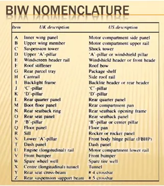
Figure-1 BIW nomenclature
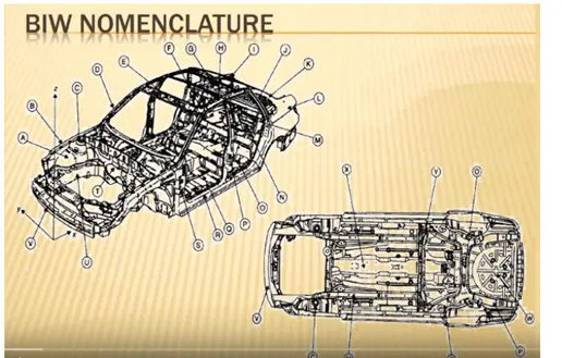
Figure-2 Picture with BIW
3. What is fixture & its types?
Answer
Fixture
- It is the device that holds the workpiece to be process or other operations like stamping and gloving by using the 3-2-1 principle
- More permanent tools that are used for assembly purposes
- Typically, does not have as much flexibility as a jig
- Most likely used for high volume production
- Made of durable material such as tool steel, iron, aluminum alloy, etc
- In general, the BIW welding fixture tool consists of no units to hold the panels together on a base unit
- Fixtures have to be quite stable and rigid to withstand the welding stress
- Welding fixtures are used to hold the parts in the required shape and are used from small parts of the plane. before welding, the parts are placed and positioned for the required shape after clamping the parts using clamping unit welding work will be carried out
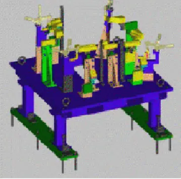
Figure-1 Fixture Prototype
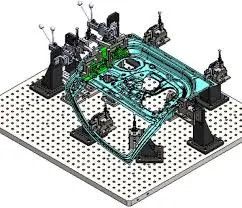
Figure-2 BIW Welding fixtures
BIW Fixture Requirement
- It should prevent distortion in the workpiece during welding operations
- The clamping need to be light and firm means the clamping force should be able to maintain the part at its required position without damaging the parts
- Placement of clamping needs to be clear of the welding area
- The fixture needs to be quite stable & rigid to withstand the welding stress
- The fixture should maintain its consistency to do defect-free operations.
BIW fixture types
They are mainly three types of fixtures
- Production fixture
- Preproduction operation fixture(PPO)
- Checking fixture
These are the fixture mainly used
- Turning fixture
- Milling fixture
- Fixture for grinding
- Fixture for broaching
- Fixture for boring /drilling
- Tapping fixture
- Fixture for welding
- Assembly fixture
- Production fixtures:-
These fixtures are used for mass production purposes. It requires high consistency through its operation to maintain the geometry of the parts so the material used is well tested for hardness & aesthetics. The quality for maintaining the dimensions & tolerances are also checked. The production fixtures need to be easy for maintenance purposes. The fixture needs some maintenance after completing no of operations. The time requires for assembly & disassembly should be as low as possible which saves lots of time.
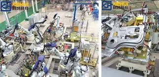
Figure-3 Production Fixture
- Preproduction operation fixtures (PPO): -
These fixtures are designed as a prototype fixture to check the feasibility of initial batch production & to check which things need to be improved before starting the production. These fixtures can be taken as the base fixtures which sets the benchmark & criteria which help us to rectify the errors that we could get from preproduction operation fixtures. In this many manual operations are involved, many engineers & quality-related persons are required. It has a large cycle time as compared to production fixtures. It requires lots of time & cost also. We have to maintain the cost of the car as low as possible so we directly go to the production fixture by considering standards, a checklist to maintain the error-free production.
- Checking fixtures: -
As the name suggests these fixtures are used for the checking purpose. No operations like welding gluing or hemming are carried out in these fixtures. The gauges are used in these fixtures to get the dimensions & the tolerances part having & the data is compared with the designed dimensions to check whether the part is ok or not. The geometry of the welded parts is also checked in this fixture to ensure the parts maintain the required dimensions & geometry.
Advantages of Fixture
- Productivity
- Interchangeability
- Skill reduction
- Cost reduction
4. What is the basic principle of fixture design?
Answer
PRINCIPLE OF FIXTURE DESIGN:
For a fixture designer, the major portion of design time is spent on deciding how to locate the workpiece in the fixture.
For any free body, there are a total of 12 degrees of freedom as below,
6 translation degree of freedom
- .X
- - X
- Y
- -Y
- Z
- - Z
And 6 rotational degrees of freedom
- Clockwise around X-axis (CROT-X)
- Anticlockwise around X-axis (ACROT-X)
- Clockwise around the Y-axis (CROT-Y)
- Anticlockwise around the Y-axis (ACROT-Y)
- Clockwise around Z-axis (CROT-Z)
- Anticlockwise around Zaxis (ACROT-2)
we must fix all 12 degrees of freedom to locate the workpiece in the fixture.
so, 12 degrees of freedom of the workpiece need to be fixed & thus we can achieve zero degrees of freedom for the workpiece

Figure Rigid Body in space
To make sure the proper fixing of the part we need to restrict all 12 degrees of freedom of the workpiece. The major portion of the time of BIW fixture designers is spent deciding how to fix these all DOF.
The jig and fixture are tools used for holding the workpiece in a correct location for mass production. Various types of fixtures (like drilling fixtures, milling fixtures, and welding fixtures) are used in industry. The 3-2-1 method is the fundamental principle for all types of fixture design.
5. Elaborate types of BIW Stations?
Answer
BIW Station is the part of BIW assembly line. The BIW assembly line is divided into zones & these zones are again divided into stations
The B/W stations are further divided into following
1) Tool stations
2) Gripper stations
3) Stand station
4) Miscellaneous stations
1)Tool stations
- A) Geo Fixtures
-In BIW we consider Tack/Geo Fixture. In Geo fixture, tack welding is done for all the parts to be assembled in that fixture. The geo fixture
defines the geometry of the part.
All the parts must be located with two locating pins (Pin can be common for two or more parts.)
-These jigs have a tight accuracy standard. In the case of Geo fixture, all the machine parts individually should be made with max tolerance of
0.02 mm. Whereas positional accuracy of the pin should be within -0.15 mm.
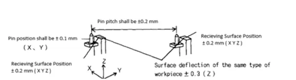
In Geo fixture spots/ MIG welding is done in such sequence that after taking out from the fixture it achieve the desired accuracy and doesn't get disturbed during transportation from Geo fixture to re-spot fixture. Geo fixture controls the sub-assembly accuracy in all the 3 axes.
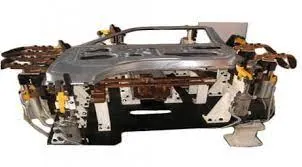
- B) Re-spot Fixtures
In BiW we consider Re-spot Fixtures in Re-spot fixture remaining tacks are completed.
Suppose in an assembly we need 50 weld lacks On one station we cannot complete all these operations because it will take more time & another station relative to the assembly will be in ideal condition
-In this type of case we carefully choose some weld tack points which will define the geometry of the part & also the assembly will not get deformed after opening the clamping or transportation due to the welding stresses
-The remaining weld tacks will be completed in the Re-spot fixture as needed. By performing this kind of operation no station will be ideal
Hence we use Re-spot fixtures
-Re-spot fixtures also have very tight positional accuracy. Re-spot pin tolerance will be -0.28 mm.
- C) Marriage Fixture
-As the name suggests the marriage of different assemblies is carried out in this fixture
- indifferent cones of assembly fine different assemblies are completed late underbody. Side body, Front body, Rear body, etc.
After this, all the parts come to the station where all parts are gets assembled by using various joining techniques like welding, Gluing Riveting, etc. The station is called a marriage tool.
D)Framer Fixture
Framer fixture is next station after the manage fixture
in framer fixture, the roof is attached to the output of the marriage fixture & it forms like a frame hence it is called a framer tool
- E) Checking Fixture
These are used to check the assembly of parts Tolerance Dimensions & coordinates
It can be of gauge type. Fixed type of automated checking fixture.
A checking gauge is a tool where the workpiece is held & different measuring gauges are introduced to ensure dimensions & repeatability Alise type checking fixture is used where the workpiece is faced with clamps & pins & CMM is used which measures the coordinates of the different points of panel or assembly Then compare with the CAD data & gives a report.
2)Grippers
A gripper is a device that enables the holding of an object to be manipulated. The easier way to describe a gripper is to think of the human hand, just like a hand, a gripper enables holding tightening, handling, and releasing of an object. A gripper is just one component of an automated system. A gripper can be attached to a robot or it can be part of a fixed automation system,
Different grippers are used in B/W as follows.
- A) Material handling gripper -
As the name suggests These grippers are used for material handling
These grippers can pick assembly from one station & will drop the assembly at another station
B)Process grippers -
These grippers are used to carry out some specific processes like gluing, welding, riveting, etc. in addition to material handling The gripper will go under gluing stand in case of gluing process & will goes under the pedestal weld stand in case of the welding process.
C)Combo Gripper
Combo grippers are the ones that can carry out multiple tasks like can do material handling & also it can carry out some specific processes like gluing, welding, etc. as well.
Weld gun-Gripper
- D) Dual Gripper
These are two-sided grippers. In case when we want one LH & one RH part, these grippers are used. It can handle the material from one station to another station
Gripper Gripper
3)Stands
Stands are used to hold parts when not in use or also it is used to mount some parts or bodies on them.
Different stands are used in BIW
A) Pedestal stands
Weld gun is mounted on the fixed stand which is mounted to the floor permanently. The gripper can carry the panel under the stand to do the operation
B) Gluing & sealer stand
Gluing gun or sealer gun is fixed to a welded or a standard stand which is grouted to the floor permanently
C) Docking stand
-The robots have some limitations such as the payload capacity of the robot & also due to lack of space
-When we select the robot for multitasking it can't do both the task simultaneously due to limitations
In this kind of case, we add a docking stand to put some equipment that is not in use for the current operation but will be required for the next operations
-Hence the robot can drop a gripper or gun & pick the next operation equipment to complete the task from the docking stand.
D) Date stamp stand
Every manufactured product has some data to stamped or to be embossed on it like serial no, batch no, Date, etc. for some future reference or data collection.
The required data is stamped or embossed by using the stamping device mounted on the stand.
4)Miscellaneous stand
A) Curing After gluing it needs some time to cool down, so we put the assembly on some belts & it will take the panel to another station &meanwhile gluing will cool down
B) Buffer stand: After some operation, we can put the no, of assemblies in this stand which is buffer stock & it can be easily transported to another
station. They are also used to store the inventory while the machine is undergoing some maintenance.
C)Take out trolleys it used to take out some panels for inspections to rectify the process is going in the right or not between the cycle.
D) Conveyor-Conveyor is the rotating path that transports the parts to the next station which are kept over it.
6. What are the basic terminologies used in the BIW fixture?
Answer
-The following terminologies are used in BIW
A) NC/Mylars/Fingers-Mylars is the component that holds the panel while operating. These are placed from the top side & the bottom side also. The top side Mylars are called Clamping Mylars & the bottom side Mylars are called Resting Mylars. Every clamping Mylars have resting Mylars. It doesn't allow deformation of the part due to welding stresses
B) Principle locating point (PLP)-These are the points that are used for the accurate location of the part to maintain the geometry of the assembly. There are lots of holes on the panel which are not accurate due to stamping operation. The PLP are defined in the drawing The positional dimensions or relative dimensions are very precise in stamping & in fixtures also.
C) Risers-
Risers are of different types like L-type rises, Square tube risers,s, etc. The riser is the manufacturing part that gives height to the assemblies) Blade
Blades are plates mounted on the riser. Other parts like cylinder, arms, etc are mounted on the blade
E) Shims
Shims are the small part that comes with the thickness of 0,1mm, 0.2mm, 0.5mm, etc. These will compensate for the stack-up tolerance which reflects at the panel holding part called Mylars. We give tolerance to all the parts of the future. Due to this tolerance, the Mylars will either lift or goes down from their defined position. If the Mylars goes down from the defined height it will make an impression or dent on the. panel. If the Mylars lift then there will be distortion due to welding stress. To adjust the Mylars At its defined positions we use shims so the panel won't be deformed & also don’t get any impression on it.
F) Rough locators
The operator can place the part in the wrong orientation mistakenly. The rough locator will work as a guide while placing the part in the future & the part will be loaded in the desired orientation, it is a part of foolproofing
G) Hardware’s
Hardware’s are like the Hex head bolts, Allen Bolts, Hex nuts, Spring washers Self-locking nuts, etc.
H) CMM
CMM stands for coordinate measuring machine. It is a device that measures the geometry of physical objects by sensing discrete points on the surface of the object with a probe. It generates a report by comparing the data with the CAD file data
1) Unit
The future is the assembly of different types of units to form a fixture. There are different units like pin unit, base unit, clamping unit, etc.
Number plates
The number plate is the aluminum embossed plate placed on each unit for easily recognizing the unit
K) Nameplate
The data like manufacturing company name, fixture type. Fixture weight etc. is embossed on the plate & joined to the fixture
M) Pivot
it is an axis about which the clamp arms will rotates
L) Clamp Arm-
The clamp arm is the part of the damp unit which moves over an axis. Over clamp arm, The Mylars are mounted
M) Pivot
It is an axis about which the clamp arm will rotate.
N) Class A Surface/Skin surface –
The outer panels of the car like hood, door, backdoor, fender. Roofs etc. are visible to the customer. The outer panels should be aesthetically very good. No, any scratches or dents are acceptable over it. While designing the fixture to the skin surface the clamping material should be soft, so that it could not able to left any impression or dent over the skin. generally, nylon or PU material is used for clamping purposes.
O) Reed switches & sensors
These are the electric components used in automated fixtures. The reed switch is an electrical switch operated by an applied magnetic field. The detects the panel is loaded or not is done by sensors.