Week 1:- Introduction to BiW and Fixtures Challenge
Q1. What is BIW & define its parts?
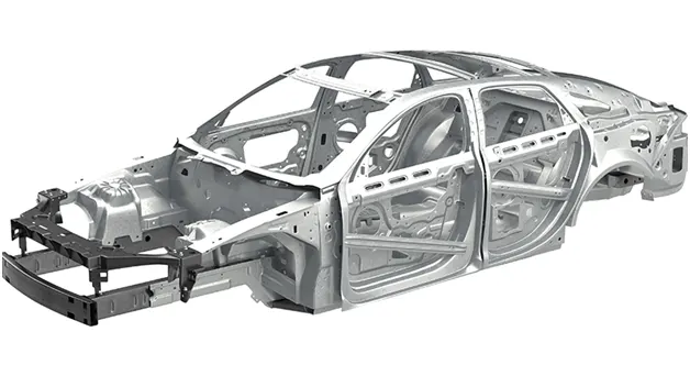
Body in white (BIW) is the stage in automobile manufacturing in which a car body's frame has been joined together, that is before painting and before the motor, chassis sub-assemblies, or trim (glass, door locks/handles, seats, upholstery, electronics, etc.) have been integrated into the structure.
Body-in-white (BiW) is the name given to a car body’s sheet when all its components—barring moving parts (e.g., hoods, fenders, etc.), trims (e.g., glass, seats, etc.), or chassis subassemblies—have been welded together. Usually, BiW constitutes about 27% of a car’s curb weight, and remains the key determinant of how the car will perform.
BiW is expected to possess a number of significant properties. It must have high tensile strength as well as high stiffness—bending, torsional, static, and dynamic. It must also provide good quality safety both to the car body and to its occupants against crashes of all kinds—front, rear, side, or even rollover. It should also be able to protect occupants from noise, vibration, and/or harshness (NVH) by absorbing or reducing these conditions. Also, it should be easy to weld and form, as well as be highly paintable and easy to design. It should provide a good surface finish that is smooth, and should also be corrosion resistant.
Given such extensive requirements, only steel and aluminum have been used for making BiW; the former is preferred for its high strength and low cost, while the latter is preferred for its lower density that helps reduce car weight.
Amid the raging debate on the suitability of aluminum as a replacement for steel in BiW, a major transformation has occurred in the form of the entire BiW being made up of carbon-fiber-reinforced plastics (CFRPs) in BMW’s i3 model, a fully electric car.
BIW Parts are mainly categorized as below:
- Body Sides
- Body side outer
- Body side inner
- Under body
- Front end under frame (Engine compartment)
- Main floor
- Rear end under frame (Rear compartment)
- Closures
- Front door
- Rear door
- Hood
- Decklid
- Roof
- Roof inner
- Roof outer
- Fender
Q2. What do you understand by BIW nomenclature?
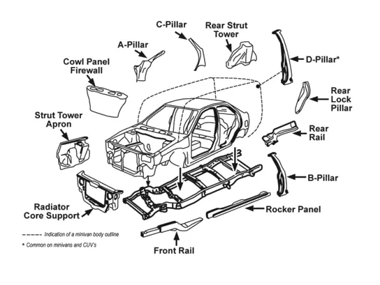
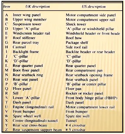
BIW Nomenclature is nothing but naming of different parts of BiW. As automotive industry is spread worldwide, different regions specify parts of BiW in different ways. Names vary from region to region. The image below shows different parts of BiW with their names.
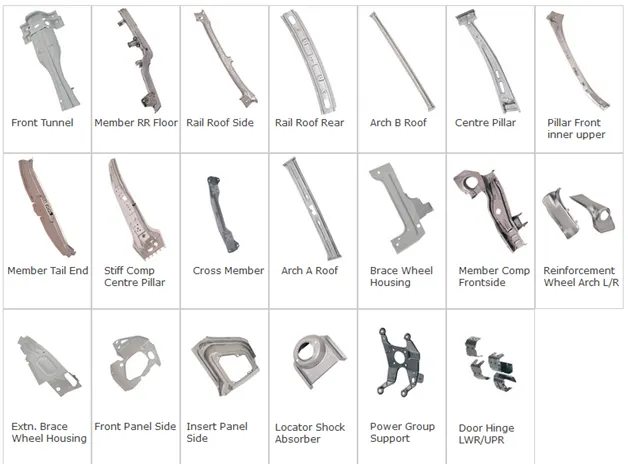
Image below shows the names of different parts in US and UK. We can observe how names vary from region to region
Q3. What is fixture? Explain its types
A fixture is a work-holding or support device used in the manufacturing industry. Fixtures are used to securely locate (position in a specific location or orientation) and support the work, ensuring that all parts produced using the fixture will maintain conformity and interchangeability. Using a fixture improves the economy of production by allowing smooth operation and quick transition from part to part, reducing the requirement for skilled labor by simplifying how workpieces are mounted, and increasing conformity across a production run.
BiW fixture types
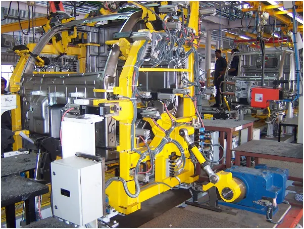
- Production fixture: As the name suggests this fixture is used for mass production. Thus these types of fixture need high dimensional accuracy and stability in terms of its mechanical properties. So material selection for these types of fixtures plays crucial role. The selected material should possess good mechanical strength as well as good surface resistance properties. Since these fixtures needs maintenance, assembly and disassembly should be as easy as possible with minimal time consumption. Image below shows BiW welding fixture.
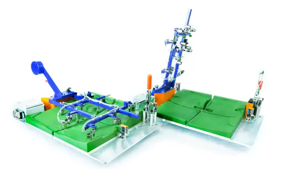
2. Pre-production fixture: Pre production also known as PPO is a fixture that is used for initial batch production study. These fixtures are basically prototype fixtures which will check the tooling feasibility of initial batch production. If needed modifications can be done on the fixtures. Image below shows the preproduction fixture.
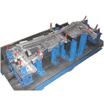
3. Checking fixtures: This fixture is used for checking assembly which came out from geo fixture. Checking fixtures are same as geo fixtures except there are no operation done like welding, gluing or hemming. Instead of that we use different in built gauges or external gauges to check various dimensions. These data will be compared with the data provided by design team.
Q4. What is the basic principle of fixture design?
A workpiece free in space can move in an infinite number of directions. For analysis, this motion can be broken down into twelve directional movements, or "degrees of freedom." All twelve degrees of freedom must be restricted to ensure proper referencing of a workpiece.
As shown in image, the twelve degrees of freedom all relate to the central axes of the workpiece. Notice the six axial degrees of freedom and six radial degrees of freedom. The axial degrees of freedom permit straight-line movement in both directions along the three principal axes, shown as x, y, and z. The radial degrees of freedom permit rotational movement, in both clockwise and counterclockwise radial directions, around the same three axes.
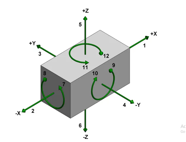
The devices that restrict a workpiece's movement are the locators. The locators, therefore, must be strong enough to maintain the position of the workpiece and to resist the cutting forces. This fact also points out a crucial element in workholder design: locators, not clamps, must hold the workpiece against the cutting forces.
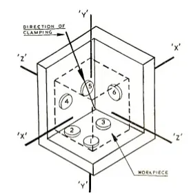
3-2-1 Principle
A widely used method of accomplishing these two objectives uses the 3-2-1 principle, so-called because it entails three steps that employ three, then two, then one fixed points of known location. Since that adds up to six fixed points, it’s also known as the six point method.
In the three steps of the 3-2-1 method, three mutually perpendicular planes, called datum planes, are introduced, one at each step. These three planes define the workpiece position, and together with opposing clamping forces fully constrain the part. Let’s take a look at the details of the 3-2-1 method.
First plane
Geometry tells us that three points are required to define a plane. This is the "3" in 3-2-1. So, three specific points are used to define the first plane. Fewer than three points cannot define a plane. Different parts may rest on different combinations of three points, resulting in variation between finished parts. The part’s six degrees of freedom have now been reduced to three. It can still move along the X or Y axes, and it can still be rotated about the Z axis.
Second plane
A second plane, if it is perpendicular to the first, can be defined by two points, the "2" in 3-2-1. The part is now constrained to one degree of freedom: movement along the Y axis.
Third plane
A third plane, if it is perpendicular to both of the first two planes, can be defined by one point, the "1" in 3-2-1. The part is now entirely constrained. It cannot move along or rotate about the X, Y, or Z axes.
Q5. Elaborate types of BIW Stations?
The BiW assembly line is one where the different types of panels are joined together in each specified zones. Each panel categories will have individual zones as under body zone, door zone, hood zone etc. A station is a place where couple of operation is done by couple of tools. Stations are categorized as shown below.
- Tools
- Geo tools
- Re spot tools
- Marriage tool
- Framer tool
- Grippers
- Material handling gripper
- Process gripper
- Combo gripper
- Stands
- Pedestal stand
- Gluing stand
- Docking stand
- Miscellaneous
- Curing
- Buffer stand
- Racks
- Pallets
- Takeout trolleys
- Conveyors
Tools
A tool is a fixture which consists of number of units together to hold a car part in general. Tools are grouped as explained before.
Geo tool: A geo tool is a fixture in which the geometry of the panels which are welded together is defined accurately. The pin tolerance for a geo pin will be of closer tolerance i.e. - 0.15 in general. For example consider panel hole size 20 mm, then the pin diameter should be 19.85 mm.
Re spot tool: A re-spot tool is a fixture in which the remaining weld spots which are not achieved in geo tool are welded for the pre welded panel from the geo tool. The pin tolerance for a re-spot pin will be of tolerance with – 0.28 mm in general. For example consider panel hole size 20 mm, then the pin diameter should be 19.72 mm.
Marriage tool or Hemming tool: It is a fixture in which the inner panel assembly and outer panel assembly are joined together. These are done by welding or by hemming in case of closure panels.
Checking stations
It is a tool fixture which is used to check the automotive parts or assemblies, ensuring all the coordinates, relative dimensions and positions as per the tolerances. A checking station can be a gauge type, fixed type and automated checking fixtures.
A checking gauge is a tool where work piece is hold and various measuring gauges are introduced to ensure the dimensions and repeatability.
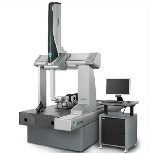
A fixed type checking fixture is used where the work piece is fixed with clamps and pins and a CMM machine is used which measures the coordinates of different points of the panel or assembly, compares it with the nominal values and gives a report.
Grippers
A gripper is a device or a fixture which holds the car panel and is fixed to the manipulating end of a robot or an end effector, also known as EOAT (End of arm tooling).
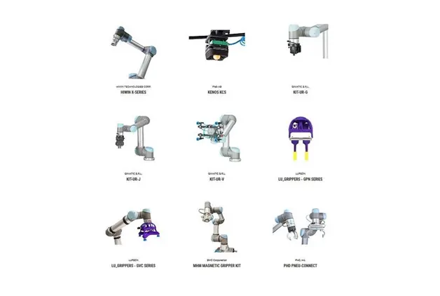
Different grippers listed before are explained below
Material handling gripper: These are designed for handling the car panel from one tool (station) to other tool (station).
Process gripper: These are designed for handling the car panel from one tool (station) to other tool (station). In addition to that it undergoes process like pedestal welding, pedestal riveting, gluing, sealing etc.
Combo gripper: These are designed for handling the car panel from one tool (station) to other tool (station) also with combination of weld gun at another side of the gripper for welding.
Dual gripper: These are designed for handling the car panel from one tool (station) to other tool (station) with two sided gripper.
Stations
Gluing and sealing stand: Gluing gun or sealer gun is fixed to a welded or a standard stand which os grouted to the floor permanently.
Docking stand: When robots are selected for multitasking like material handling and welding, which cannot carry both due to some limitations, the robot will pick the gripper or gun after completing the respective operation with the help of docking stands.
Date stamp stand: The panel will get the date embossed on to it, with the date stamping device mounted on this date stamp stand.
Miscellaneous stations
Curing: After gluing, it needs some time to cool down, so we put assembly on some belts and it will take the panel to another station and meanwhile gluing will cool down
Buffer stand: After some operation we can put the number of assemblies in this stand which is buffer stock and it can be transported to another station in easy way. They are also used to store the inventory while the machine is undergoing for some maintenance.
Takeout trolley: It is used to take out some panels for inspection to rectify the process is going in right or not between the cycles.
Conveyors: They are used to transfer panel from one station to another station. It can be of two types gravity and powered.
Q6. What are the basic terminologies used in BiW fixture?
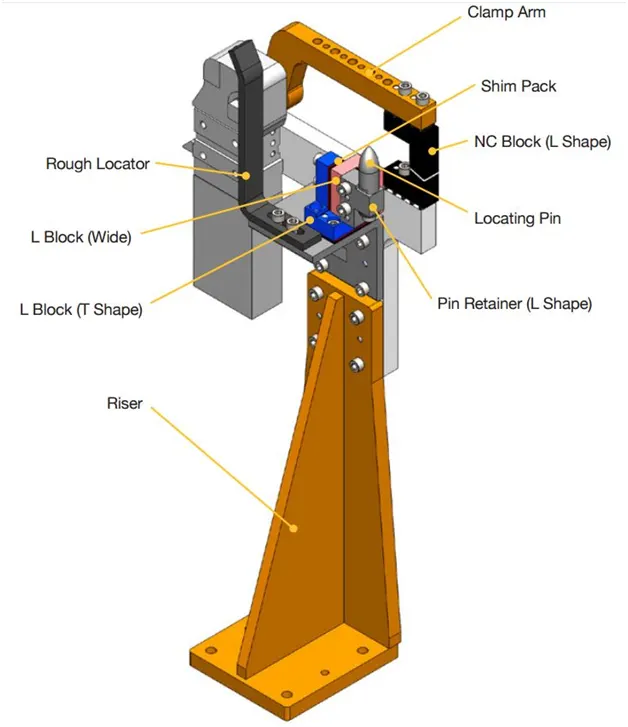
NC/Mylars/Fingers: These are used to hold panel. Top side mylar is called clamping mylar and bottom side is called resting mylar. It prevent panel from deforming while welding.
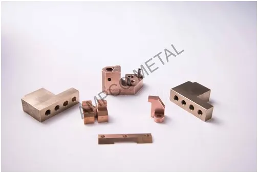
Principle locating point: These are points which are used for the accurate location of part to maintain the geometry of assembly.
Risers: These are basically manufactured parts and are used to give height to assembly. They can be of L-type, welded or square tube or frame type.
Blades: These are plates attached to riser. Other part like cylinder, arms etc are mounted on the blade.
Shims: In fixture we are providing tolerance to each part mostly manufactured. Those tolerance tend to stack up and reflect together. In order to avoid that we use shims so we can easily adjust after assembly. Shims comes in thickness of 0.1, 0.2, 0.5 etc.
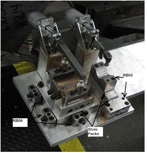
Rough locators: These are used majorly for manual fixture. There is chance that operator can place part in wrong orientation mistakenly. The rough locator will work as a guide while placing the part in the fixture and part will be loaded in desired orientation.
Hardwares: Hex head bolts, allen bolt, hex nuts, spring washers, self locking nuts etc.
CMM: It is a device that measures the geometry of physical objects by sensing discrete points on the surface of object with probe. It generates the report by comparing the data with the CAD file data.
Units: The fixture is assembly of different types of units. There are different unit like pin unit, base unit, clamping unit etc.
Number plates: These are aluminum embossed plate placed on each unit to recognize the unit.
Name plate: The plate on which basic information described like company name, fixture name, fixture weight, panel name are embossed and joined to fixture.
Clamp arm: It is part of clamp unit which moves about axis. Over these clamps mylars are mounted
Pivot: It is axis about which clamp arm will rotates.
Class A surface: The outer panels of car like hood, door, backdoor, fender, roof etc are visible to customer. This very most outer surface or aesthetic surface is called class A surface.
Reed switches & sensor: These are electronic components used in automated fixtures.