Week 1:- Introduction to BiW and Fixtures Challenge
1.What is BIW & define its parts?
Ans: BIW(Body in white): In the Automotive Industry BIW (Body in White) is the common terminology used to mention the car sheet metal welded structure (body shell). In today's situation, automotive BIW is made of steel (various steel grade material -DP, DD, HDP etc.) as well as made of aluminium alloy (e.g. AUDI A8).Usually, BiW constitutes about 27% of a car’s curb weight, and remains the key determinant of how the car will perform. BiW is expected to possess a number of significant properties. It must have high tensile strengthas well as high stiffness,bending, torsional, static, and dynamic. It must also provide good quality safety both to the car body and to its occupants against crashes of all kinds—front, rear, side, or even rollover, meeting the Federal Motor Vehicle Safety Standard No. 208. It should also be able to protect occupants from noise, vibration, and/or harshness (NVH) by absorbing or reducing these conditions. Also, it should be easy to weld and form, as well as be highly paintable and easy to design. It should provide a good surface finish that is smooth, and should also be corrosion resistant.
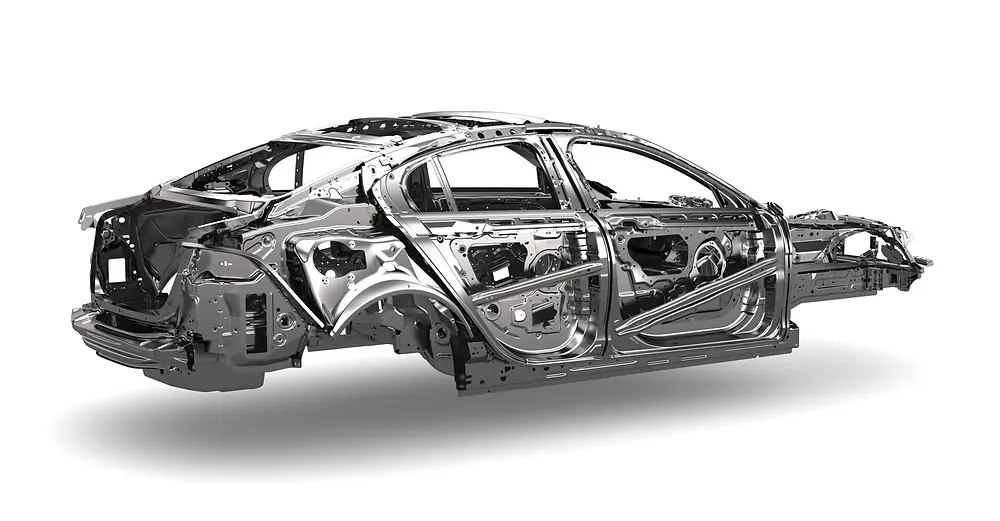
BIW is divided into two types
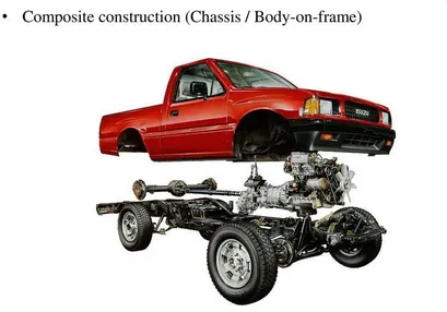
1.Body on Frame Construction
2.Monocoque construction (Chassis in built in Body)
Body on Frame Construction:
- Body is mounted on a separate chassis / frame
- Used in utility vehicles, trucks, buses
- Wheels and suspension are mounted on chassis
Monocoque construction (Chassis in built in Body)
- Used in all the passenger cars and to some extent in utility vehicles
- Chassis is inbuilt with BIW itself and there is no separate chassis
- Wheels and suspension are directly mounted to BIW

BIW Parts:
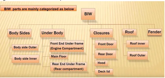
BIW is classified into 5 major omponents
1.Body Side
2.Under Body
3.Closures
4.Roof
5.Fender
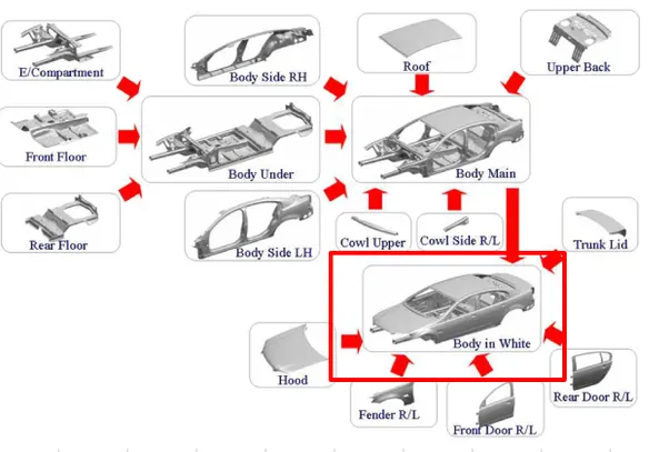
Body Side: The core element of any car is the body structure. The car body connects all the different
components; it houses the drive train and most importantly carries and protects passengers
and cargo. The body structure needs to be rigid to support weight and stress and to securely
tie together all the components.
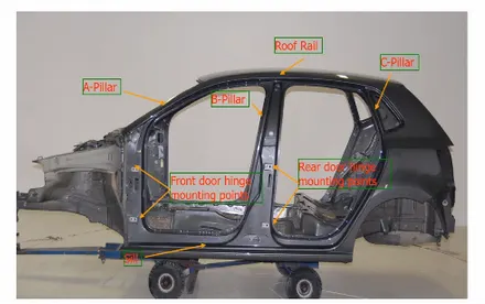
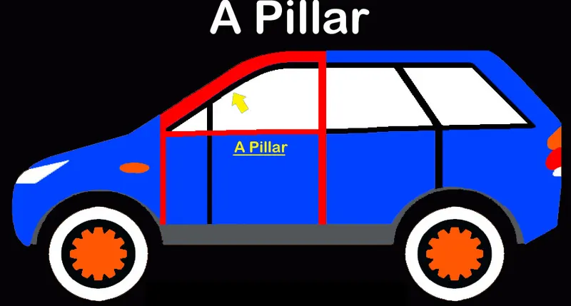
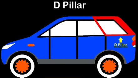
A Piller : It is the front most support of the roof. The A-pillar is made of strong steel alloys. This is to make it withstand a crash and meet safety standards. The blind spot occurs due to the blocking of the driver’s vision by the A-pillar. So, some car-makers made the A-pillar slimmer and chamfered to decrease the blind spots.
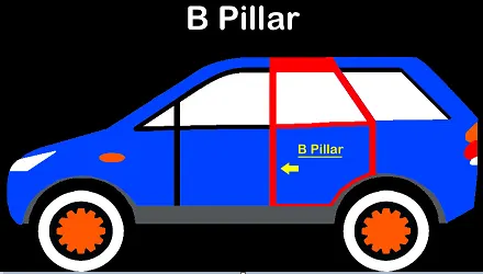
B-Piller: It is the second support to the roof. It is the comples structure as the front door closes and the rare door is hinged to the B piller.
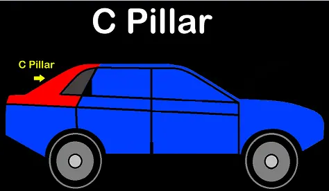
C-Piller: It is the rearmost support to the roof of two row seating system.
D-Piller: It is the fourth piller actually, the D pillar is the rearmost pillar of the vehicle’s body. However, the D pillar is provided mainly for the Station wagons.
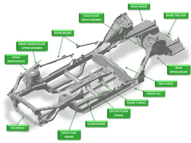
Under Body: It is the bottom part of the BIW. it carries the maximum weight. It has 3 components
- Front end underframe : It is an engine compartment area where all the engine mountings are made
- Main Floor: Transmissions, Instrumental panel, seats and other components are arranged in this compartmant
- Rear end underframe: It provides Rear boot space and used to place stepheny.
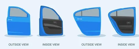
Closures: Closures are a non-structural part of the vehicle that are hinged to the body frames, such as doors, to allow entry and exit from the vehicle. Automotive closures are a critical part of the vehicle, as they contribute to vehicle safety and add functional value. Automotive closures have witnessed a significant amount of development, in terms of design, weight, and features, for the last few years.
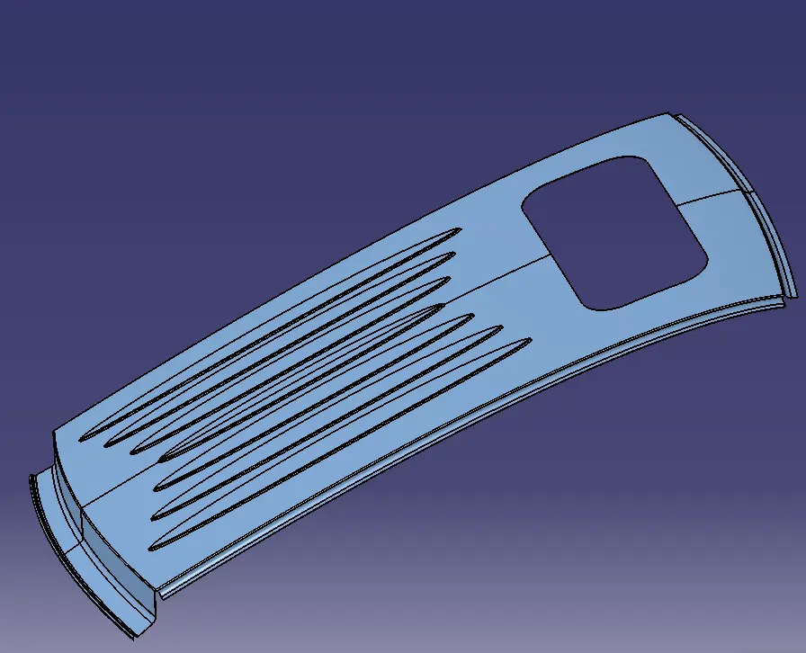
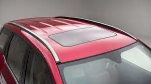
Roof: An automobile roof is the portion of an automobile that sits above the passenger compartment, protecting the vehicle occupants from sun, wind, rain, and other external elements. A sunroof is a window in the roof of a vehicle that allows additional light and fresh air to enter the cabin. They come in many sizes and styles, and nearly all new versions are motor-driven, though some older sunroofs are manually operated.
Roof of an automobile has
- Bow roof railing
- Center roof railing
- Rear roof railing
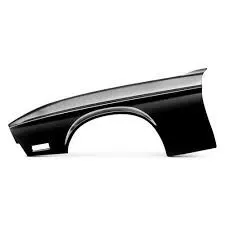
Fender: Fender is the American English term for the part of an automobile, motorcycle or other vehicle body that frames a wheel well (the fender underside). Its primary purpose is to prevent sand, mud, rocks, liquids, and other road spray from being thrown into the air by the rotating tire.
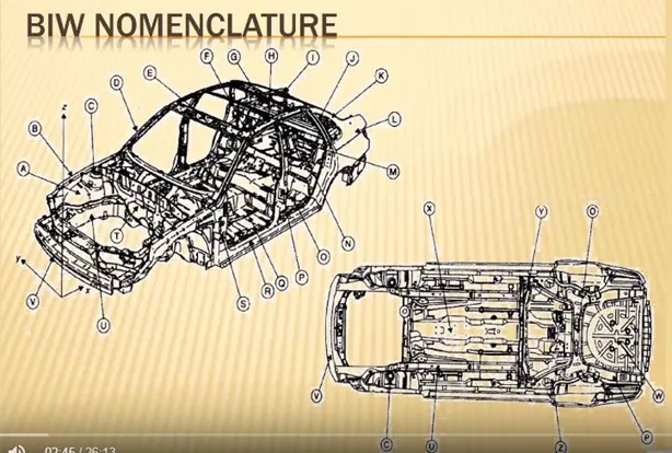
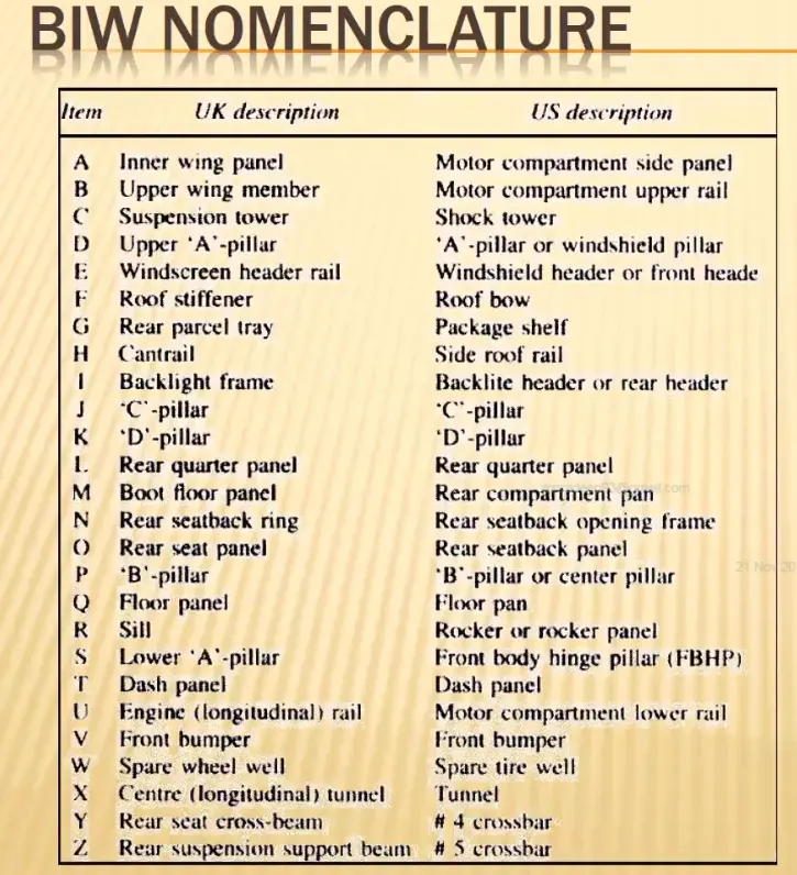
2.What do you understand by BIW nomenclature?
Ans: Nomenclature is basically choosing of names for things. As BIW has many no of parts the have different names. As there are differnt names for the BIW parts in different areas BIW nomenclature has been introduces to make it common all around the world and make it confirtable.
3.What is fixture & its types?
Ans: Fixture: A fixture is a work-holding or support device used in the manufacturing industry. Fixtures are used to securely locate (position in a specific location or orientation) and support the work, ensuring that all parts produced using the fixture will maintain conformity and interchangeability. It uses 3-2-1 principal to hold the workpiece.
Types of fixtures:
- Production fixtures
- Pre production operations fixtures
- Checking fixtures
Production fixtures: These are use in mass production. It requires high consistency to maintain the geometry of the parts. these are divided into various types based on their work they are
- Welding fixture
- Riviting fixture
- Screwing fixture
- Riviting fixturr
Pre production operations fixtures: As the name indicates it is used brfore the produvtion, it is also call as prototype fixture. It is used to check the feasability and and check if any error are there before going to the production fixtures.
Checking Fixtures: These fixtures are used to check weather all the operations like welding, gluing, hemming etc. These are also used to check the dimentions, GD & T of the parts after production.
4.What is the basic principle of fixture design?
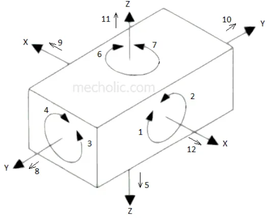
Ans: The main principal of the fixture is 3-2-1 principal. We know that there are 12 degees of freedon for a body in space. We have to constrain all the 12 DOF by using this principal. Tha 12 DOF are 6 Translation DOF and 6 Rotational DOF
6 Translation DOF are
- X positive
- X Negetive
- Y positive
- Y Negetive
- Z positive
- Z Negetive
6 Rotational DOF are
- X - Axis Clockwise
- X - Axis Anti Clockwise
- Y - Axis Clockwise
- Y - Axis Anti Clockwise
- Z- Axis Clockwise
- Z - Axis Anti Clockwise
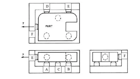
- The work piece is resting on three pins A, B and C which are inserted in the base of the fixed body.The work piece cannot rotate about the axes XX and YY and also cannot move downward. In this way, the five degrees of freedom 1,2,3,4 and 5 have been arrested.
- Two pins D and E are inserted in the fixed body, in a plane perpendicular to the plane containing pins A, B & C. Now the work piece cannot rotate about the Z axis and also it cannot move towards the left. Hence the addition of pins D and E restrict three more degrees of freedom, namely 6, 7 and 8.
- Another pin F in the second vertical face of the fixed body, arrests degree of freedom 9.
5.Elaborate types of BIW Stations?
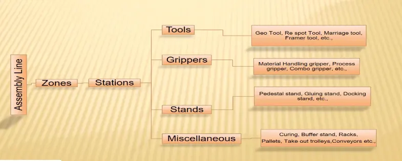
Ans: BIW station is one of the majot part in the BIW assembly. BIW assembly is classied into zones and zones are classfied into stations. The types of stations are
- Tools
- Grippers
- Stands
- Miscellaneous
Tools
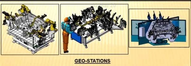
a.Geo Tool: Geo tool defines th geometry of the structure, it is where the assembly or welding operations are done. It have more accuracy and the pin size of the geo tool must me very close to the hole size. All the parts must be located by the two pins.
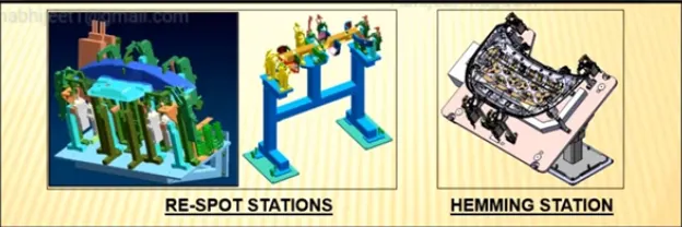
b.Respot tool: As the name name indicates the weld spots which cannot be acheived by geo tool are done here. It is used to decrease the ideal time production cycle. Suppose we neek to make 70 weld spots in a geo station but it cannot be done in a single station as it consumes more time which makes the other stations in the assembly line to be ideal. Hence in this condition we us respot tool to make the other weld spots.
c.Marrage Tool: It is used to join the inner panel assenbly and outer panel assembly. These joints are either joint by welding or hemming.
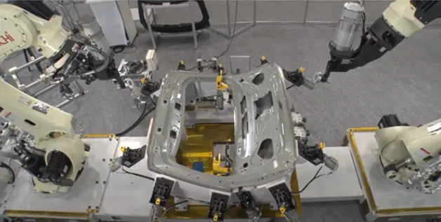
d.Framer Tool: It is the next step of the marrage tool. After assemblying the outer and inner panels roof is attached to the output of marrage tool by forming frame, hence it is called as framer tool.
e.Checking Tool: It is used to check the assembly components to ensure all the parts are accurate and in dimenssion. Checking tool can be either gauge type, fixed type and automated checking.
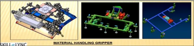
Grippers: Gripper is a divece which holds the car panel and is fixed to manuplating end of the robot. grippers should be as light as possible as they are fixed to the end of the robot arms. The types of grippers are
a.Material Handling Gripper: These are used to move the car panel from one station to another station
b.Process Grippers: These are used to perform joining operations welding and joining to the car panels. After performing joining operation these will drop the panels in next station for further process.
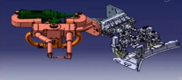
c.Combo Grippers: As name indicates it is combimnation of process and material handeling grippers. One side of gripper has welding tools to perfom joining and other side is used to move panel from one station to another station.
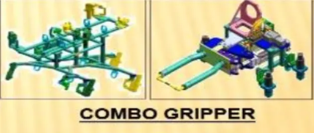
d.Dual Grippers: It is also used to move cal panel from one station to another station but it has gripper on its both sides so than we can move two panels at a time. It is mostly used for identical panels.
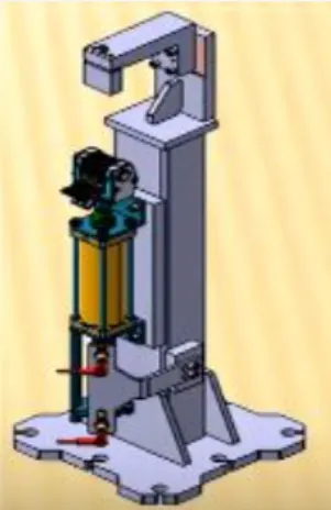
Stands: Stands are used to hold the panels. These are fixed to the floor to maintain accuracy. Types of stands are:
a.Pedestal Stands: Weld gun is welded to the stand. The process gripper will take the panel under this pedestal welding and perform welding operation.
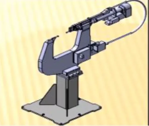
b.Gluing or Sealing stand: Gluing gun is fixed to this stand to prform gluing operation.
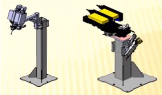
c.Docking Stand: When robots are assaigned multitasking like material handeling, joining operaton it cannot be done simultaneously as robots have restrictions. In this case we add docking stand to pt some equipment which is not use for current operation will be used for next operation. Hence robot can drop gripper and pick up next operation equipment to perform next operation.
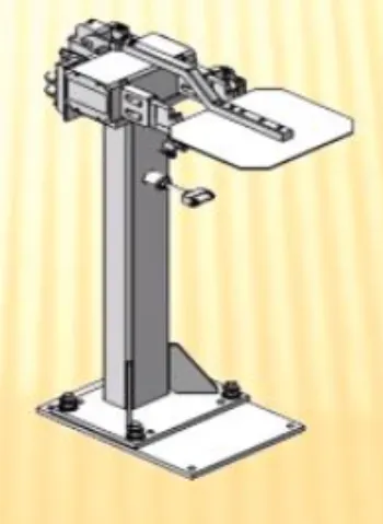
d.Data stamp stand: To print data like Serial No., Manuf. Date, Batch no on the part we use this tool. The data can be either stamped or embossed.
Miscellaneous
a.Curing: After performing tooling operation it need to be cooled. So to cool the assembly we put them on the belts to as it cools down until it reaches the next station.
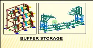
b.Buffer Stand: After perfoming some assembly operations those assemblies are stored in this stand until it gose to next process. Thes can be easly moeved to another station.
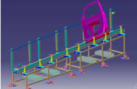
c.Conveyor: Conveyors are used to move panels from one station to another. This are of two types Gravity and power.
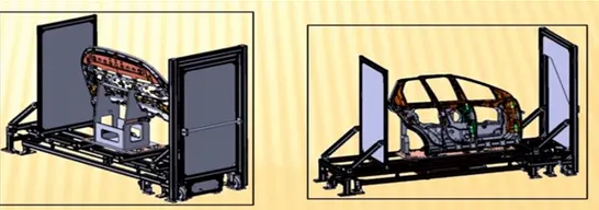
d.Take out Trolly: It is used to take the car panel out of the work station.
6.What are the basic terminologies used in the BIW fixture?
Ans: The basic terminologies of BIW fixtures are
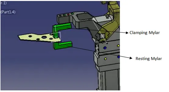
1.NC/MYLARS/FINGERS
These parts are used to hold the panel. The top side of Mylar are called clamping and bottom side is called resting mylar. every clampin of mylar should have resting. It prevents deformation while welding the panel.
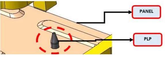
2.Principle Locating Point (PLP)
These are used for locating the panels by using pins. These arer used to main maintain geometry of part in assembly.
3.Raiser
It is used ti raise the height of the fixture. These are of two types
- L type raiser
- Square tube type raise
4.Blade
Blades are the plates attached to the raiser. Ther cylinder and other arms are mounted to the blade.
5.Shims
Shims are small parts of thichness 0.1,0.2, 0.3 mm. These are used to compensate the difference formed due to stack up tolerence.
6.Rough Locators
These are majorly use in manual fixtures. These are used as the guide to place the part in correct position and orientation.
7.Hardwares
Hardware are the fastners like Nut, bolt, washers, self intersecting nuts, hexa bolts etc.
8.CMM
It is known as coordinate measuring machine. is is used to check the geometry of physical objects by sensing descreet points on the surface.
9.Units
The fixture is the assembly of different units. Some of the units used in fixture assembly are base unit, pin unit, clamp unit etc.
10.Number plates
These are aluminum embossed plate placed on each unit to recognize the unit.
11.Name plate
It is the plate on which the company information like company name, fixture name, fixture weight etc are embossed on it. This plate is joined to the fixture.
12.Clamp arm
It is the part of clamping unit which holds the clamping mylar and will rotate along axis.
13.Pivot
It is an axis about which the clamparm will rotate.
14.Class A surface
The outer panel of car like Hood, roof , tailgate, doors etc are visible to the cousmers. These should be asthetically good. These surfaces are called class A surface. While assembling fixtures should not cause damage to these surfaces. So while designing we should make shure that the clamping material should be soft so taht it will not creat any dent or scrach to these surfaces.
15.Reed switches and Sensors
These are electronic components used in automotive fixtures . These are used only when the the fixtures are fully automatic or semiautomatic that run through PLC. Sensors are used to detct weather the part is present or not where as reed swth confirms the position.