Week 1:- Introduction to BiW and Fixtures Challenge
1.What is BIW & define its parts?
Ans:
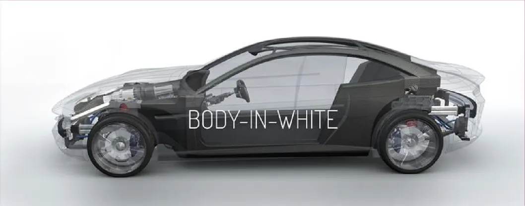
BIW stands for Body In White, and this term derives from automobile manufacturing in which car body parts are joined together before processes like painting, motor chassis sub-assemblies, doors, glass, handles, locks, seats, and electronics part assemblies that have to be integrated into the structure.
<!--[endif]-->
- The Body in White includes all the sheet metal components that form the car car's structure such as floor, pillars, roof, door, and side panels.
- It does not include the engine trasmission or interior components
- It works just like the skeleton of the body, which protects inner assemblies and gives vehicle a desired shape.
- It provide structural integrity and foundation for the entire vehicle.
- There are two kinds of BIW Structures in use:
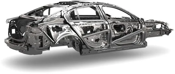
1. Monocoque Body structure:In monocoque body, chassis is in-built in the BIW itself and there is no separate chassis. Wheels are directly mounted to the BIW with the help of suspension system.
<!--[endif]-->
Jaguar XE Aluminium monocoque
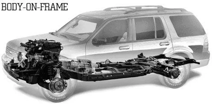
2. Frame mounted Body structure: In Frame mounted body, body is mounted on a separate chassis/frame and the wheels are mounted on the chassis and not to the body.
- BIW Parts are consists under several structure and these structures are divided in following substructures:
<!-- [if !supportLists]-->1. <!--[endif]-->UNDERBODY STRUCTURE
<!-- [if !supportLists]-->2. <!--[endif]-->FRONT END STRUCTURE
<!-- [if !supportLists]-->3. <!--[endif]-->BODY SIDE STRUCTURE
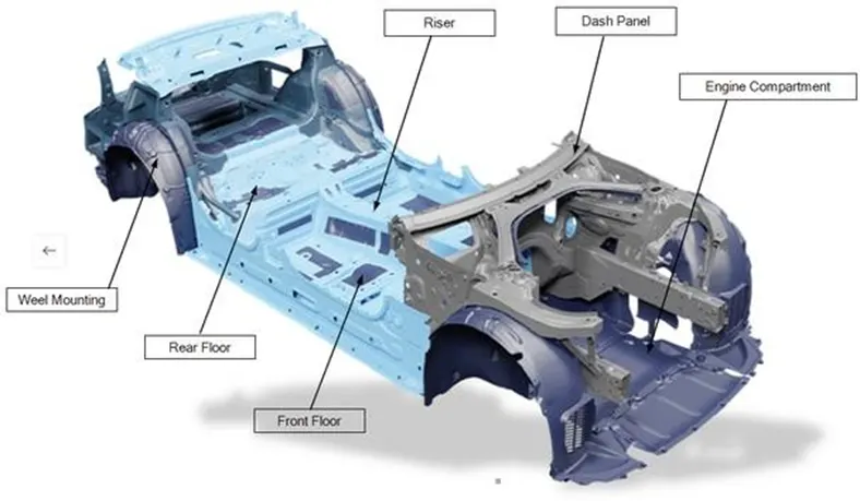
CLOSURES UNDERBODY Structure consists of following major panels:
•Dash Panel: Dash panel provides a partition between engine and the driver/passenger cabin inside car.
•Front Floor: Front Floor provides a base for seats mounting and provides partition between transmission/propeller shaft/ground and the cabin.
•Riser: Riser connects Front floor to Rear Floor by providing a level difference.
•Rear Floor: Rear Floor is the floor on the Rear of the car and provides a partition from ground also provide base for Rear seat mounting.
•Rear wheel house: Rear Wheel house is an encasement around the Front wheel.
<!--[endif]-->
FRONT END structure consists of following major panels:
•Plenum Panel: Plenum is the part located between the front windshield and the bonnet of an automobile. It is primarily used as an air inlet to the HVAC during fresh air mode operation
•Front Wheel House/Fender: Front Wheel house or Fender is an encasement around the Frt wheel.
•Wing Panel: Wing panel are the outer most side panel in the front.
•Cowl: Cowl is the portion of the body bounded by the front fenders, the base of the windshield, and the rear edge of the hood.
•Upper Tie Bar: Upper tie bar is the upper panel in front connecting the two sides (RH/LH) of Front structure.
•Lower Tie Bar: Lower tie bar is the lower panel in front connecting the two sides (RH/LH) of Front structure.
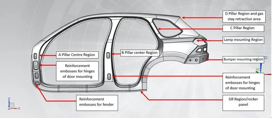
BODY SIDE structure consists of following major panels:
•A-Pillar: A-Pillar is the front most support to Roof.
•B-Pillar: B-Pillar is the second support to the roof and situated on the locking side of the Front door.
•C/D Pillars: C-Pillar is the Rear most support to roof in case of a two row seats car, OR third support to the roof. D-pillar is the fourth support to the roof and usually on the rear side of quarter panel.
•Ring Pillar: Ring panel is a structure panel connecting the rear portion of the body to front, and constitutes a big part in side structure.
•Quarter Pillar: Quarter panel is rear most panel of a body side structure.
•Drip Rails/Gutters: Drip rails/Gutters is an exposed channel applied to the roof over the side windows to direct water away from the windows and to cover structural welding.
 <!--[endif]-->
CLOSURES consists of following major panels:
•All Doors: It provide access to the interior of the car for passengers and the driver. They can be opened and closed to allow people to get in and out of the vehicle.
•Hood/Bonnet: It is a hinged panel that covers the engine compartment and provides access to the engine and other crucial components, such as the battery and fluid reservoirs. The primary purpose of the hood is to protect the engine from dirt, debris, and weather elements, while also allowing for maintenance and repairs.
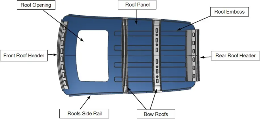
ROOF structure consists of following major panels:
•Roof: It is a car top or the portion of an automobile that sits above the passenger compartment, protecting the vehicle occupants from sun, wind, rain, and other external elements.
•Headers: Header is the structural member above the windshield at the juncture with the forward edge of the roof panel.
•Bows: Bows are essential for maintaining the shape and structure of car roof it provide strength to roof panel of car.
<!--[endif]-->
<!-- [if !supportLineBreakNewLine]-->
<!--[endif]-->
2. What do you understand by BIW nomenclature?
Ans:
BIW nomenclature often relates to the identification or labelling of various parts and components utilised in the assembly of the vehicle's body.
This system is critical for effective communication, quality control, and assembly operations. Specific parts, subassemblies, or even individual production procedures can be identified using nomenclature.
The particular nomenclature used in BIW may differ from one manufacturer to the next, and it can be rather extensive and complex due to the multiple parts and sub-assemblies. To precisely identify each element, it may include a variety of codes, part numbers, and descriptions.
Assume you have a vehicle door assembly that is in the BIW stage. Its nomenclature could be as follows:
Front Left Door Assembly is the name of the part.
Part No. : XXX-XXXXXX
Complete door assembly for the vehicle's front left side, including inner panel, outer panel, hinges, window glass, and electrical harness.
Please keep in mind that the actual nomenclature will vary depending on the car model and the manufacturer's internal systems and norms. Furthermore, the automobile industry's vocabulary and processes may develop over time, so it's always advisable to adhere to the most recent standards and practises utilised by the specific manufacturer.
<!-- [if !supportLineBreakNewLine]-->
<!--[endif]-->
<!-- [if !supportLists]-->4. <!--[endif]-->What is fixture & its types?
Ans:
- The primary purpose of a BIW fixture is to hold and position the various body panels and components in the correct alignment during the assembly process.
- A fixture is a device which holds the work piece to be processed by using 3-2-1 principle.
- It consists of numbers of unit to be mounted on base unit
- Its resist distortion in work piece during working process
- By using these fixtures, car manufacturers can ensure that each vehicle's body is consistent, of high quality, and meets safety standards before proceeding to the next stages of production.
There are following types of fixture:
<!-- [if !supportLists]-->1. <!--[endif]-->Production Fixture
<!-- [if !supportLists]-->2. <!--[endif]-->Pre-Production Operation Fixture
<!-- [if !supportLists]-->3. <!--[endif]-->Checking Fixture
1.Production Fixture:
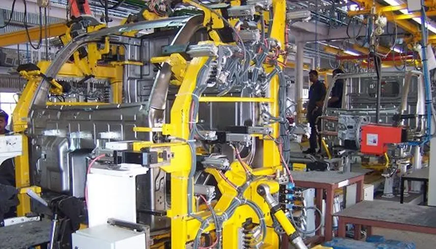
- As the name implies, this fixture is employed in mass production.
- It is the fixture on which the car body is assembled and delivered to the customer.
- The primary purpose of production fixtures is to ensure accuracy, repeatability, and efficiency in the manufacturing process by securely holding the work piece in the correct orientation.
- Production fixtures facilitate faster and more efficient manufacturing processes. Workers can quickly load and unload work pieces from fixtures, and the precise positioning reduces the need for manual adjustments, leading to increased productivity and throughput.
- There are various types of production fixtures, including drilling fixtures, milling fixtures, welding fixtures, assembly fixtures, and inspection fixtures. Each type is specialized for a specific manufacturing process.
<!--[endif]-->
2. Pre-Production Operation Fixture:
- A pre-production fixture, also known as a prototype fixture or development fixture.
- It is a specialized tool or device used in the early stages of product development and manufacturing.
- It is employed before the full-scale production of a product begins and is specifically designed to aid in the testing, validation, and refinement of prototypes or initial product designs.
- This fixture helps identify any design flaws, functionality issues, or areas for improvement before moving to full-scale production.
- The main purpose of a pre-production fixture is to assess and optimize the product's design, functionality, and manufacturability.
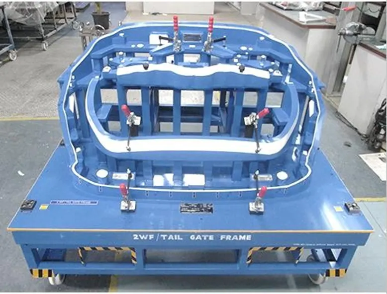
3.Checking Fixture:
- A checking fixture, also known as a gauging fixture, inspection fixture, or control fixture.
- It is a specialized tool or device used in quality control and inspection processes during manufacturing.
- Its primary purpose is to verify the dimensional accuracy and quality of a workpiece or product by comparing it to the intended design specifications.
- Checking fixtures play a crucial role in ensuring that the manufactured parts meet the required standards and tolerances.
- It is similar to GIO Fixture
<!--[endif]-->
<!-- [if !supportLineBreakNewLine]-->
<!--[endif]-->
4.What is the basic principle of fixture design?
Ans:
Here are the basic principles of BIW fixture design:
<!-- [if !supportLists]-->1. <!--[endif]-->Part Geometry and Variability: BIW fixtures must be custom-designed for each specific vehicle model to accommodate the unique body geometry and variations. The fixture should account for the tolerances and dimensional variability of the body panels to achieve precise alignment during assembly.
<!-- [if !supportLists]-->2. <!--[endif]-->Locating and Clamping: BIW fixtures must provide precise locating points and robust clamping mechanisms to securely hold the body panels in the correct positions during welding and assembly. The locating points should accurately reference key points on the body to maintain dimensional accuracy.
<!-- [if !supportLists]-->3. <!--[endif]-->Modular Design: Due to the frequent model changes in the automotive industry, BIW fixtures should be designed with modularity in mind. A modular fixture design allows for easier adaptation to new vehicle models, reducing lead times and costs when transitioning to different projects.
<!-- [if !supportLists]-->4. <!--[endif]-->Rigidity and Stability: BIW fixtures must be rigid and stable to resist deflection and vibration during welding and assembly operations. The fixture's material and construction should ensure it can withstand the forces and loads applied during the manufacturing process.
<!-- [if !supportLists]-->5. <!--[endif]-->Accessibility and Ergonomics: Design considerations should include providing easy access to welding and assembly areas, as well as accommodating the movement of robotic welding equipment or manual assembly tools.
<!-- [if !supportLists]-->6. <!--[endif]-->Simulation and Validation: The fixture design should be simulated and validated using computer-aided engineering (CAE) tools to ensure it meets the required performance criteria before fabrication. This helps identify potential issues and optimize the fixture design for better results.
<!-- [if !supportLists]-->7. <!--[endif]-->Repeatability and Accuracy: BIW fixtures should ensure high repeatability and accuracy in the assembly process, contributing to consistent quality in the final products.
<!-- [if !supportLists]-->8. <!--[endif]-->Welding Considerations: For fixtures used in welding processes, special attention should be given to thermal expansion and distortion during welding to maintain dimensional integrity.
<!-- [if !supportLists]-->9. <!--[endif]-->Maintenance and Serviceability: The fixture design should consider ease of maintenance and repair to minimize downtime and ensure long-term usability.
<!-- [if !supportLists]-->10. <!--[endif]-->Safety Features: Safety is paramount in any manufacturing process. BIW fixtures should incorporate safety features to protect operators and prevent accidents during assembly and welding operations.
For any free body there are total twelve degrees of freedom as below:
6 translation degrees of freedom: +X, -X, +Y, -Y, +Z, -Z
And 6 rotational degrees of freedom
Clockwise around X axis
Anticlockwise around X axis
Clockwise around Y axis
Anticlockwise around Y axis
Clockwise around Z axis
Anticlockwise around Z axis
We must fix all the 12 degrees of in order to locate work piece in fixture.
Let discuss more about locating principle:
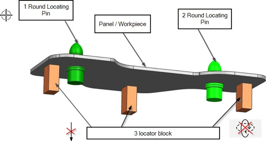
3-2-1 Principle:
- The 3-2-1 principle is a widely used method in fixture design to ensure accurate and repeatable positioning of a work piece within a fixture.
- The principle involves using three points of contact to establish the primary (X, Y, Z) orientation of the work piece, two points to establish the secondary orientation, and one point to constrain the rotation about the third axis.
- This method simplifies the fixture design process and provides a stable and reliable reference for the work piece during manufacturing operations.
- it allows for a faster fixture design process and ensures that the work piece is securely held in place, minimizing errors and scrap during production.
- Here's how the 3-2-1 principle works:
3 Three Points of Contact (Primary Orientation):
- Three locator blocks to establish part plane and these locators are usually positioned on the primary locating surface.
- These restrict one axial movement downward and four radial movement.
- It can't rotate about x-axis and y-axis and thus restrict four radial movement.
- Together these three locator restrict 5 degree of freedom
2 Two Points of Contact (Secondary Orientation):
- The next two points of contact establish the secondary orientation of the work piece. These points are typically located on a separate plane perpendicular to the datum plane.
- These points constrain the work piece’s rotation about one axis (commonly the Z-axis), providing stability and alignment during machining or assembly.
- Round locating Pin in a round hole that define location in four direction (4-way) perpendicular to the plane
- These restrict 4 axial movement
1 One Point of Contact (Rotation):
- The final point of contact restricts the rotation of the work piece about the third axis, typically the X or Y-axis.
- This point ensures that the work piece remains aligned and prevents rotation during manufacturing operations.
- Another round locating pin in a slot that define two of the direction of the other pin (2-way) as shown in fig.below
- This restrict 2 degree of freedom
<!--[endif]-->
5. Elaborate types of BIW Stations?
Ans:
Here are a few typical BIW station types:
<!-- [if !supportLists]-->1. <!--[endif]-->Welding Station: The numerous body panels are welded together at these stations using robotic welding cells or hand welding fixtures to create the structural framework of the car. The body parts are precisely and securely joined at welding stations using specialised fittings and welding equipment. 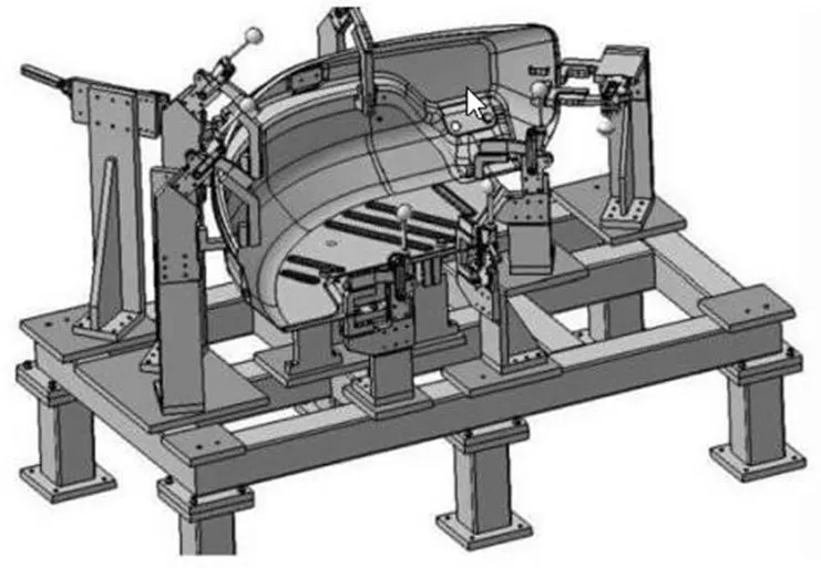
<!-- [if !supportLists]-->2. <!--[endif]-->Assembly Stations: At assembly stations, various body panels and sub-assemblies are put together to form bigger assemblies. Door, hood, trunk, and fender assemblies are attached to the main body structure.
<!-- [if !supportLists]-->3. <!--[endif]-->Under body Stations: Under body stations are responsible for putting the vehicle's floor pans, chassis, and suspension parts together.
<!-- [if !supportLists]-->4. <!--[endif]-->Body Side Stations: These facilities put the side panels of the car together, including the doors and quarter panels.
<!-- [if !supportLists]-->5. <!--[endif]-->Stations for the roof and hood: These stations are responsible for putting the vehicle's roof and hood together.
<!-- [if !supportLists]-->6. <!--[endif]-->Closure Stations: To guarantee perfect alignment and fitment, closure stations concentrate on fitting a variety of closure components, including as doors, hoods, trunks, and tailgates.
<!-- [if !supportLists]-->7. <!--[endif]-->Marriage Stations: Also referred to as "marriage lines," marriage stations are the locations where the body shell is linked or wed to the chassis or under body of the vehicle. When the rolling chassis is coupled with the entire body structure, this is a crucial stage in the assembly process.
<!-- [if !supportLists]-->8. <!--[endif]-->Body Inspection Stations: Before going on to the next stage of assembly, these stations are outfitted with specialised checking fixtures and inspection tools to assess the dimensional correctness and quality of the body structure.
<!-- [if !supportLists]-->9. <!--[endif]-->Glazing Stations: Glass installation for windows and windscreens is handled by glazing stations.
6. What are the basic terminologies used in the BIW fixture?
Ans:
Now finally let us understand the basic terminology used in the BIW fixture:
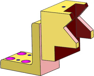
- NC/Mylar/Finger: Mylar is the component which holds the panel while operations. These are placed from top side and from bottom side also. The top side mylar called Clamping Mylar and the bottom side Mylar called as Resting Mylar. Every clamping Mylar has Resting Mylar. It doesn’t allow deformation of the part due to welding.
 <!--[endif]-->
- Principle locating point (PLP): These are the points which are used for accurate location of the part to maintain the geometry of the assembly. There are lots of holes on the panel which are not accurate due to stamping operation. The PLP are defined in the drawing.
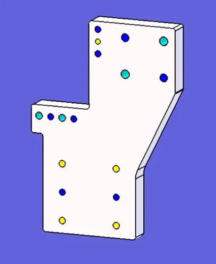
- Blade: These provide support to the assembly base.
<!--[endif]-->
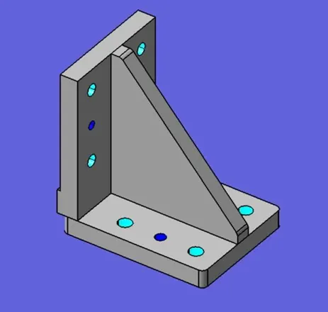
- Raiser: Raiser are adjustable standing brackets that are used to define the height of the clamps and fixture. Additional parts such as cylinders, mounting plate are also attached to the raiser. Raiser is of different type like L-type riser, square tube riser etc.
<!--[endif]-->
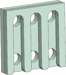
- Shims: Shims are the small parts which come with the thickness of 0.1mm, 0.2mm, 0.5mm etc. These will compensate the stack up tolerance which reflects at the panel holding part called Mylar. We give tolerances to all the parts of the fixture. Due to this tolerance the Mylar will either lift up or goes down from its defined position. If the Mylar goes down from the defined height it will make impression or dent on the panel. if the Mylar lift up then there will be a distortion due to welding stress. To adjust the mylar at this defined position we use shims so the panel won’t deformed and also don’t get any impression on it.
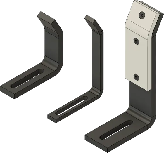
- Rough Locators: The operator can place the part in wrong orientation mistakenly. These is kind of tool proofing which allows the operator to load the component only in the correct location and orientation.
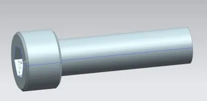
- Hardware: These are bolts, nuts and self-locking nuts etc.
<!--[endif]-->
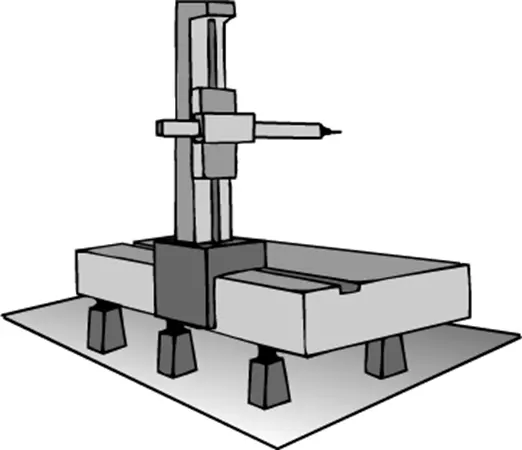
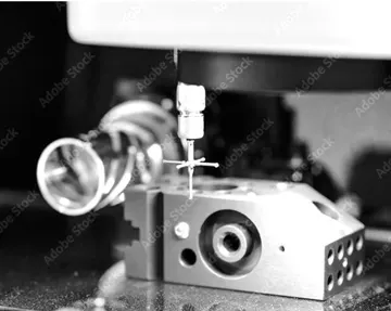
- CMM: CMM full form Coordinate Measuring machine. This device measures the geometry of the physical objected by sensing discrete point on the surface of the object with a probe. it’s generating report by comparing the data with the CAD file data.
- Units: There are different type of units that forms a fixture. They are classified as base unit, hole unit, pin unit, clamp unit.
- Number Plate: It is a plate which have number embossed on it. Which helps is recognizing the part later.

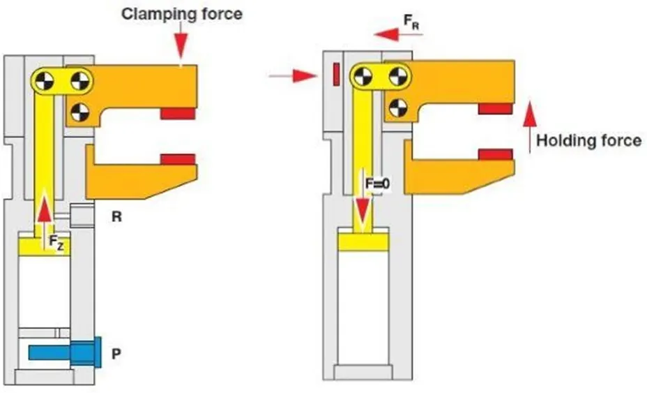
- Clamp Arm: In a clamp assembly unit the arm that move is called as clamp
<!--[endif]-->
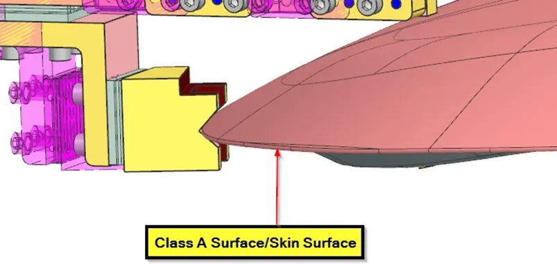
- Class A surface/Skin surface: The outer panel of the car like hood, door, backdoor, fender, roof etc. Are visible to the customer. The outer panels should be aesthetically very good .no any scratch or dent not acceptable over it .it while designing the fixture to the skin surface the clamping material should be soft so that it could not able to left any impression or dent over skin. Generally, nylon or PU material is used for clamping purpose.
- Reed switches: These are the electronic switches which are operated by the sensors or sometime manually.
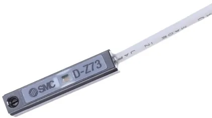
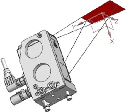
- Sensors: These are the electronics devices which senses the component on the fixture and helps to operate or send input commands to the other mechanical or electronic components.
 <!--[endif]-->
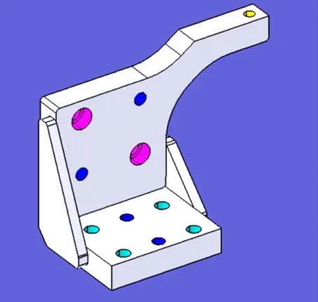
 - Weldment: Weldment is the joining of two or more pieces using welding. To produce a weldment, the thumb rule is to have a 5 mm overlap on each other plate to allow for welding. A weldment can have any number of plates and any size.
<!--[endif]-->
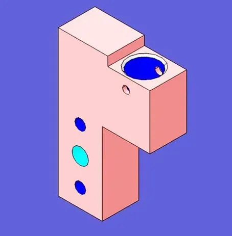
- Pin Block: Pin Block is also called Pin Retainer. This block holds the pin and restricts the rotational motion of the pin. Pin Block can be either manufactured one or Standard.
<!--[endif]-->
- L Block: A plate shaped as L is called an L block. This portion serves as a link between mylar and Blade. L blocks are commonly used to provide shimming. L blocks are not always used for shimming; their applications vary depending on the situation. In other cases, they are simply utilized to connect one item to another. In addition to the L block, another block in the shape of a T is used. As a result, this block is known as a T Block.

<!--[endif]-->