Week 1:- Introduction to BiW and Fixtures Challenge
1. What is BIW & define its parts?
Body in white (BIW):- It is a stage in automobile manufacturing in which sheet metal components of the car body have been joined together, using different techniques such as welding (spot, MIG/MAG), riveting, clinching, bonding, laser brazing, etc.
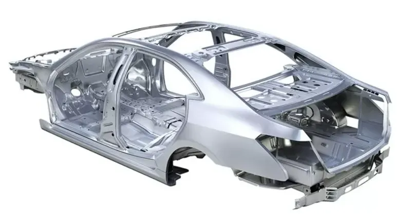
Fig 1:- BIW of a car
Body in White, or BIW, is a stage in the production of automobiles in which all sheet metal components such as the roof, body side, underbody, backdoor, cross members, and other components are welded together and the resulting body is dipped in a primer solution, which has a greyish color and thus gives the body its name. The car's shape is determined by the BIW, which is obtained after welding and before painting.
BIW can be made into two structures:
1. Monocoque structure:- The term monocoque means the chassis integrates with the complete body as one part. It is a French term that means ‘single shell’ or ‘single hull.’ Monocoque construction is significant for reducing the vehicle’s overall weight by integrating the chassis and the body into a single unit. Other vehicle components such as the power train, steering, suspension, and brakes are directly mounted to the vehicle’s body in this design. In monocoque construction, the exterior skin supports the structural load. Hence, it is also called structural skin.
Manufacturers directly attach these components to the body or onto the sub-frames, which are then mounted to the main body. Many modern vehicles use monocoque construction. Manufacturers especially plan and design monocoque structures with the help of crumple zones to keep away the shock of occupants’ impact
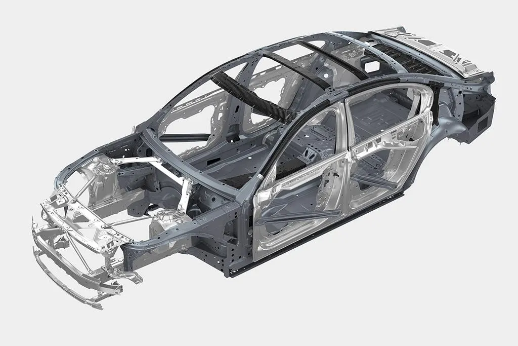
Fig 2:- Monocoque structure
2. Body-on-frame structure:- It is also known as ladder frame construction, is a common motor vehicle construction method, whereby a separate body or coach is mounted on a strong and relatively rigid vehicle frame or chassis that carries the powertrain (the engine and drivetrain) and to which the wheels and their suspension, brakes, and steering are mounted. While this was the original method of building automobiles, body-on-frame construction is now used mainly for heavy trucks, pickups, and predominantly large SUVs.
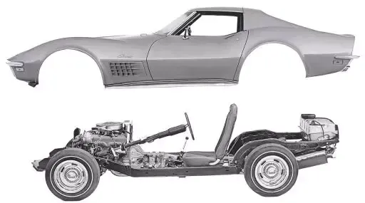
Fig 3:- Body-on-frame structure
BIW parts are mainly categorized below
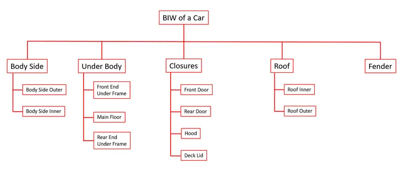
Table 1:- BIW parts
1. Body Side
The body side structure consists of the following major panels:
a. A-pillar:- A-Pillar is the frontmost support to the Roof.
b. B-pillar:- B-Pillar is the second support to the roof and is situated on the locking side of the Front door.
c. C/D pillars:- C-Pillar is the Rearmost support to the roof in case of a two-row seats car OR third support to the roof. D-pillar is the fourth support to the roof and is usually on the rear side of the quarter panel.
d. Ring panel:- Ring panel is a structure panel connecting the rear portion of the body to the front, and constitutes a big part of the side structure.
e. Quarter panels:- The quarter panel is the rearmost panel of a body side structure.
f. Drip rails/Gutters:- Drip rails/Gutters are an exposed channel applied to the roof over the side windows to direct water away from the windows and to cover structural welding.
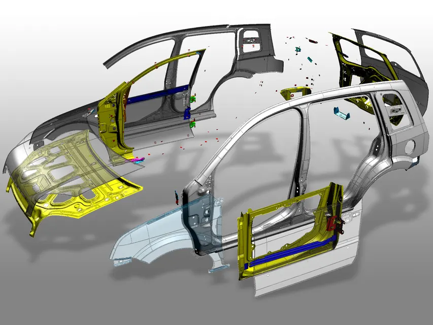
Fig 4:- Bodyside
2. Underbody
An Underbody Structure consists of the following major panels:
a. Dash panel:- Dash panel provides a partition between the engine and the driver/passenger cabin inside the car.
b. FRT Floor:- provides a base for seat mounting and provides a partition between the transmission /propeller shaft/ground and the cabin.
c. Riser:- The riser connects the front floor to the rear floor by providing a level difference
d. Rear Floor:- Rear Floor is the floor on the Rear of the car and provides a partition from the ground and also provides a base for Rear seat mounting.
Front end structure consists of the following major panels:
a. Plenum Panel:- Plenum is a chamber located between the throttle body and the runners of the intake manifold, used to distribute the intake charge evenly and enhance engine breathing.
b. FRT wheelhouse/ Fender:- FRT Wheel house or Fender is an encasement around the FRT wheel.
c. Wing panel:- Wing panels are the outermost side panel in the front.
d. Cowl:- Cowl is the portion of the body bounded by the front fenders, the base of the windshield, and the rear edge of the hood
e. Upper tie bar:- Upper tie bar is the upper panel in front connecting the two sides (RH/LH) of the Front structure.
f. Lower tie bar:- Lower tie bar is the lower panel in front connecting the two sides (RH/LH) of the Front structure.
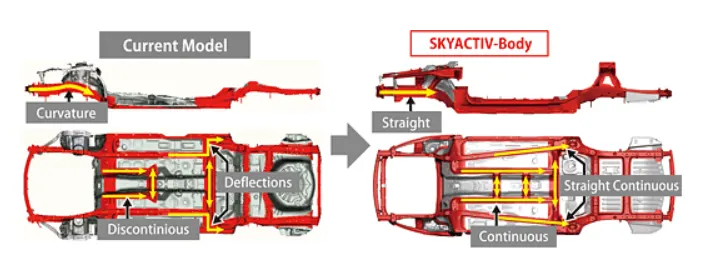
Fig 5:- Underbody
3. Closures
Closure refers to parts that are hinged to the car body. all doors, including hood & tailgate/back door.
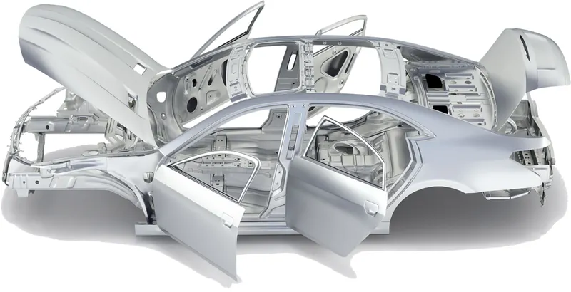
Fig 6:- Closures
4. Roof
a. Roof Outer:- An automobile roof or car top is the portion of an automobile that sits above the passenger compartment, protecting the vehicle occupants from sun, wind, rain, and other external elements. Because the earliest automobiles were designed in an era of horse-drawn carriages, early automobile roofs used similar materials and designs.
b. Roof Inner:- Roof inner consists of roof structural members like Front roof rail, bow roof rail, center reinforcement rail & rear roof rail.
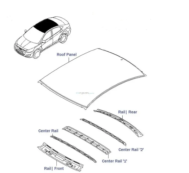
Fig 7:- Roof
5. Fender
Fender is the American English term for the part of an automobile, motorcycle, or other vehicle body that frames a wheel well (the fender underside).
Its primary purpose is to prevent sand, mud, rocks, liquids, and other road spray from being thrown into the air by the rotating tire. Fenders are typically rigid and can be damaged by contact with the road surface.
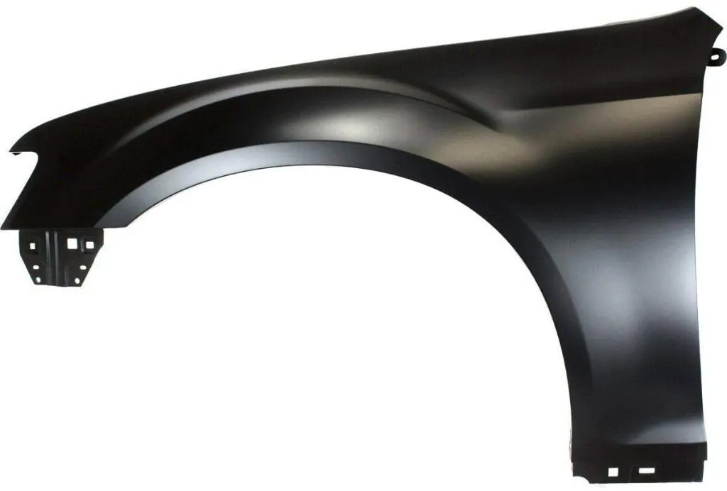
Fig 8:- Fender
2. What do you understand by BIW nomenclature?
BIW nomenclature
Hence from the definition of nomenclature, we came to know that the terms/names applied to the BIW COMPONENTS are known as BIW NOMENCLATURE.
The terms are standard but they differ in some countries.
As automotive industries spread worldwide, the terms and standards will be different for similar components.
For example, One component of BIW is known as the inner wing panel in the UK description another side of the same component of BIW is known as the Motor compartment side panel in the US description.
Below I have attached some common terms of BIW which differ from the UK to US descriptions.
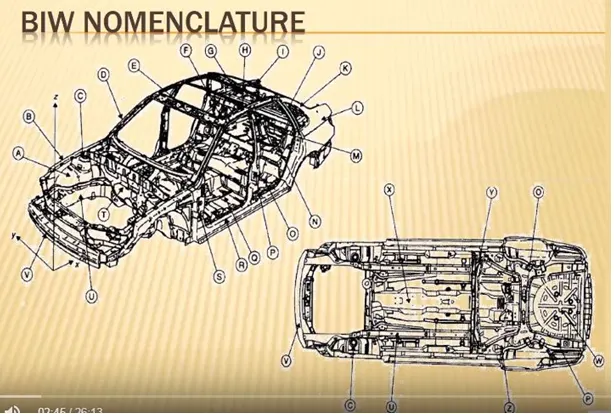
Fig 9:- BIW nomenclature
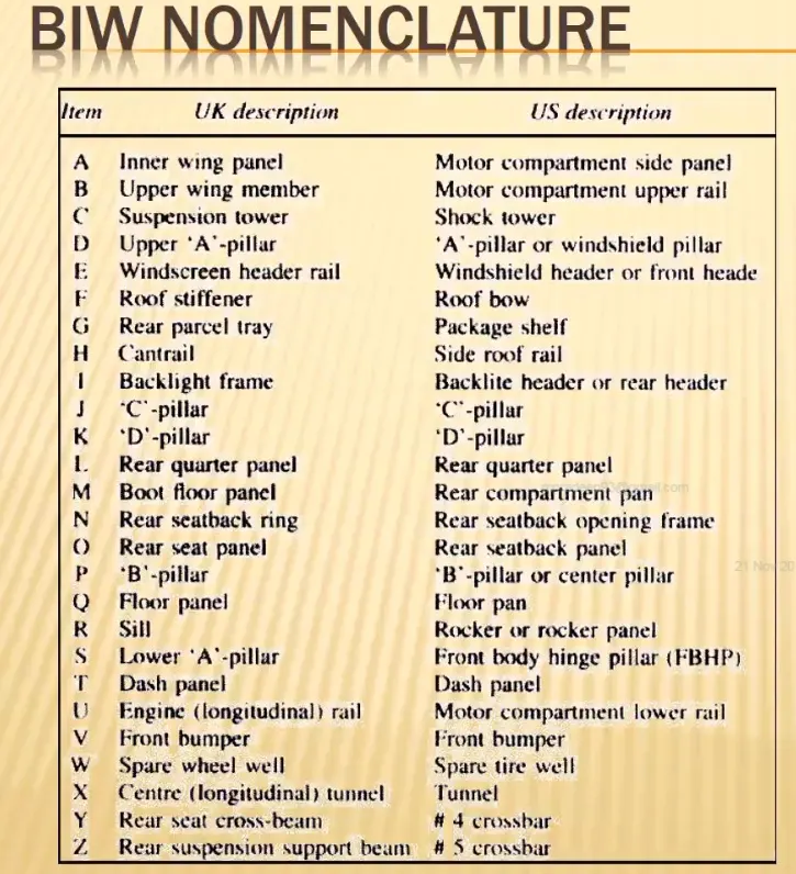
Fig 10:- BIW nomenclature
Inner wing panels:- These are where the wheels go on the vehicle. They have all or part of the wheel arches built in, protecting the wheels and car from debris and moisture kicked up from the road.
Fig 11:- Inner wing panel
The upper wing member:-The wing is a part of the frontal car body, covering the wheel arch of the steering axle and merging into the bonnet and the front. The good thing about the wing is its simple replacement.
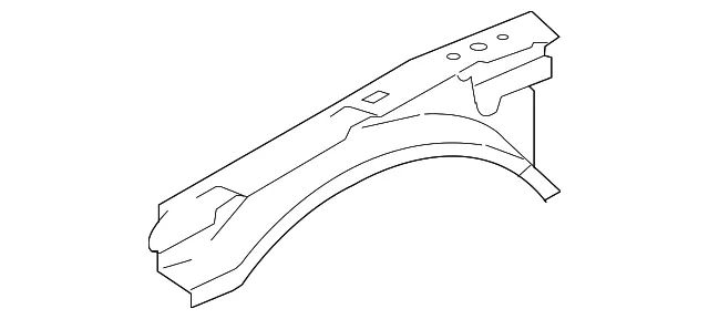
Fig 12:- Upper wing member
Suspension Tower:- Shock towers are well-known vehicular body parts. Generally, a shock tower is secured to body components framing an engine compartment and provides an attachment point for an upper end of a suspension damper, such as a strut or shock absorber.
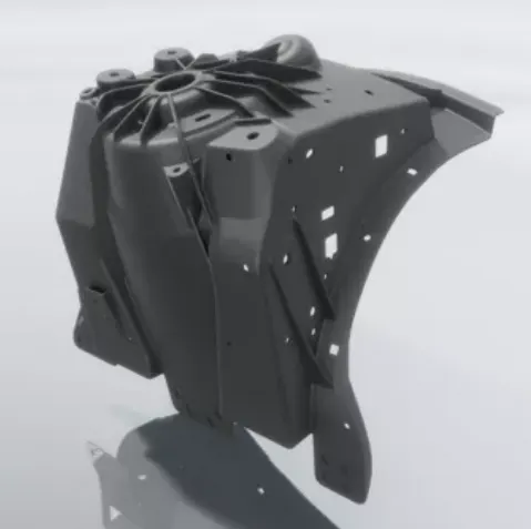
Fig 13:- Suspension Tower
Pillars:- Pillars” refer to roof pillars, and they’re lettered front to back. A-Pillars straddle the windshield, B-Pillars are in the middle of the passenger compartment (just behind the front doors) and C-Pillars are at the rear of the passenger compartment.
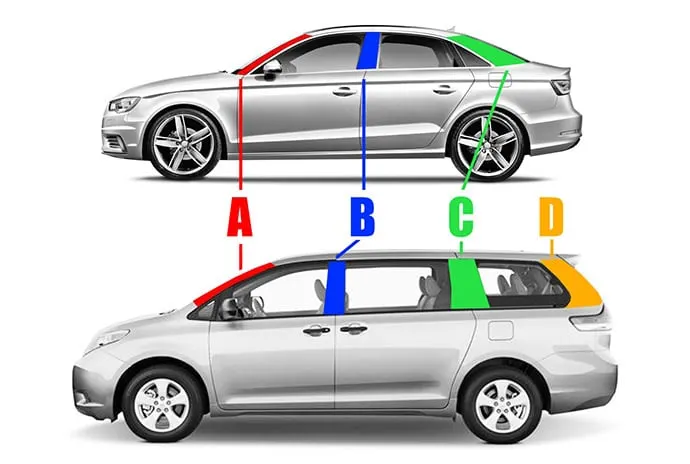
Fig 14:- Pillars
Windscreen header rails:- The header rail is the reinforced side section of the car's roof. If you're sitting behind the wheel, it will be sitting top right behind the headlining, out of sight and out of mind.
Roof bow:- A vehicle roof bow assembly includes a roof bow member and a pair of telescoping mounting brackets. The roof bow member is configured to extend in a lateral side-to-side direction along an underside of a vehicle roof panel. The telescoping mounting brackets each have a first end and a second end with the first end having a side rail attachment flange configured for rigid attachment to a first vehicle roof side rail and a roof panel attachment flange configured for rigid attachment to the vehicle roof panel and the second end being attached to the roof bow member. The telescoping mounting brackets are disposed at opposite ends of the roof bow member.
Rear Header:- Header is the structural member above the rear windshield at the juncture with the forward edge of the roof panel.
Fig 15:- Roof Rails
Rear parcel tray:- It is the shelf inside your car, behind the rear seats. It is usually removable and you can even store some lightweight items on it.
Fig 16:- Rear parcel tray
Side roof rails:- These are the structural members of the BIW of a car.
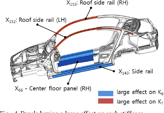
Fig 17:- Side roof rails
Quarter panel:- It is the body panel (exterior surface) of an automobile between a rear door (or only door on each side for two-door models) and the trunk (boot) and typically wraps around the wheel well.
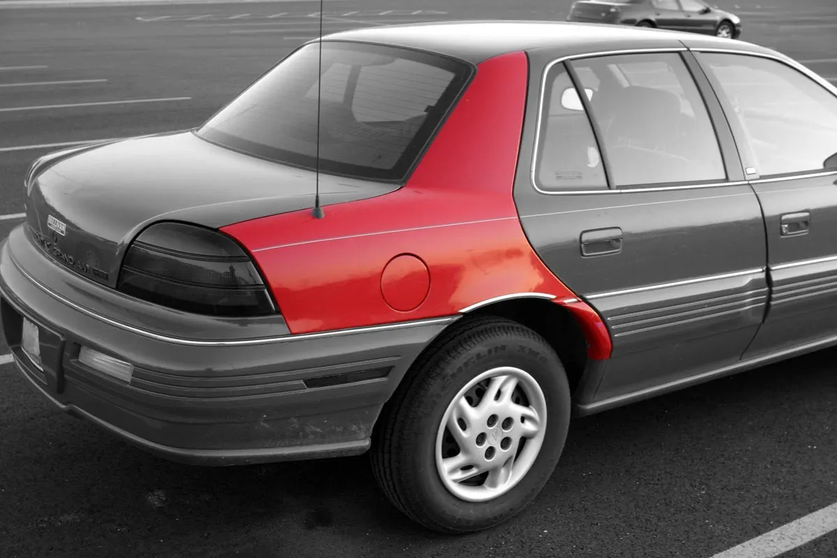
Fig 18:- Quarter panel
Boot floor panel:- Floor panel is a large sheet metal stamping that often incorporates several smaller welded stampings to form the floor of a large vehicle and the position of its external and structural panels.
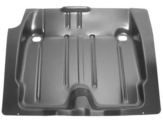
Fig 19:- Boot floor panel
Floor panel:- is the large panel of the automobile body that incorporates with the smaller parts welded in it.
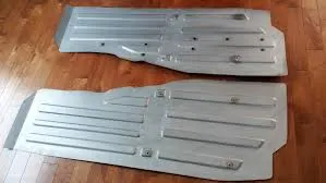
Fig 20:- Floor panel
Sill:- The sills of the car are part of the bodywork. The bodywork is the shell of the car and protects parts such as the engine from dirt and premature damage. The sill has a specific function, which is to protect and hide the bearing parts. The sills can be found under the doors, against the underside of the car.
Fig 21:- Sill
Dash panel:- Provides partition between Engine & the driver cabin.
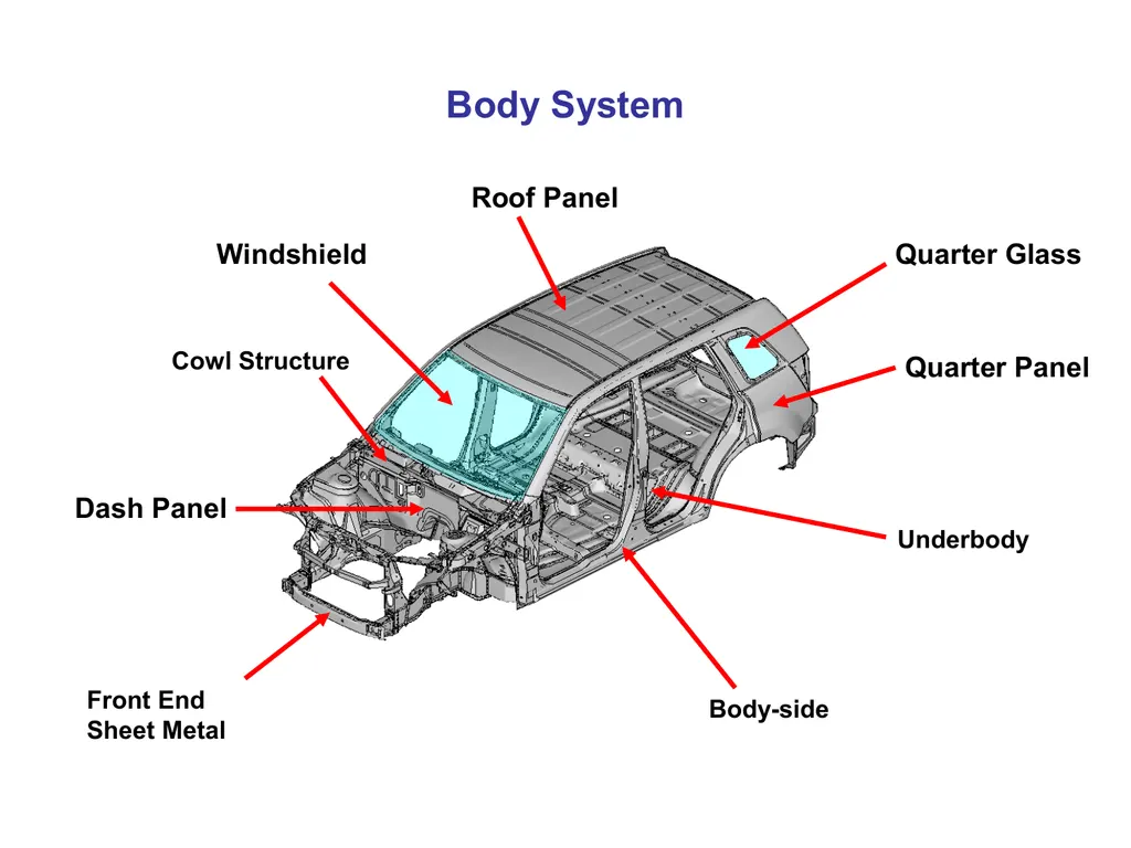
Fig 22:- Dash Panel
Fig 23:- Front Bumper beam
Cross car beams are complex parts, which make a decisive contribution to the stability and safety of every vehicle in which they are used. As a single cross strut in the vehicle interior they ensure that, in the event of a side impact, the passenger compartment is not compressed. Cross-car beams also hold the steering wheel, the airbags, and the entire dashboard. Depending on the model, we can manufacture this crucial part in steel or aluminum.
Rear Suspension support beam:- The rear suspension of a car is the mechanical system that holds the car's body and frames aloft as the connection between the car and the road. The rear suspension includes the frame (or body connections in a unibody vehicle), joints, bearings and bushings, rods, shock absorbers, springs, wheels, and tires.
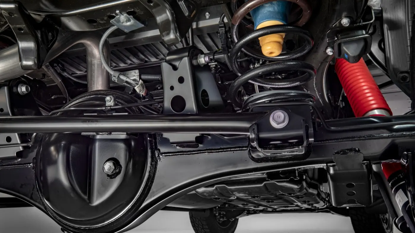
Fig 24:- Rear Suspension support beam
Fig 25:- Rear Suspension support beam
3. What is a fixture & its types?
Fixture:- It is a work-holding or support device used in the manufacturing industry. Fixtures are used to securely locate (position in a specific location or orientation) and support the work, ensuring that all parts produced using the fixture will maintain conformity and interchangeability.
In BIW fixtures, the fixtures are designed to hold no. of parts during welding. It is necessary to hold the parts at the proper location to avoid distortions & to maintain the required geometry of the parts.
Fig 26:- Fixture
BIW fixture requirements
- It should prevent distortions in the workpiece during the welding operation
- The clamping needs to be light but firm means the clamping force should be able to maintain the part at its required position without damaging the part.
- The placement of clamping needs to be clear in the welding area.
- The fixture needs to be quite stable & rigid to withstand the welding stresses.
- The fixture should maintain its consistency to do defect-free operations.
BIW fixture Types
1. Production fixtures:- These fixtures are used for mass production purposes. It requires high consistency through its operation to maintain the geometry of the parts so the material used is well-tested for hardness & aesthetics. The quality for maintaining the dimensions & tolerances is also checked. The production fixtures need to be easy for maintainable purposes. The fixture needs some maintenance after completing several operations. The time required for assembly & disassembly should be as low as possible which saves lots of time.
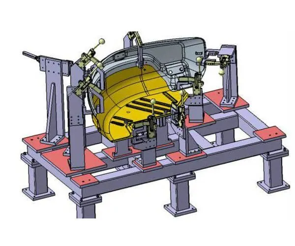
Fig 27:- Production Fixture
2. Pre-production operation fixtures (PPO)
These fixtures are designed as prototype fixtures to check the feasibility of initial batch production & to check which things need to be improved before starting the These fixtures can be taken as the base fixtures which sets the benchmark & criteria which help us to rectify the errors that we could get from preproduction operation fixtures. In this many manual operations are involved, and many engineers & quality-related persons are required. It has a large cycle time as compared to production fixtures. It requires lots of time & cost also. We have to maintain the cost of the car as low as possible so we directly go to the production fixture by considering standards, and a checklist to maintain the error-free production.
3. Checking fixtures
As the name suggests these fixtures are used for checking No operations like welding gluing or hemming are carried out in these fixtures. The gauges are used in these fixtures to get the dimensions & the tolerances part has & the data is compared with the designed dimensions to check whether the part is ok or not. The geometry of the welded parts is also checked in these fixtures to ensure the parts maintain the required dimensions & geometry.
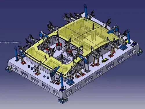
Fig 28:- Checking Fixture
4. What is the basic principle of fixture design?
A fundamental concern in metalworking is locating the part to be machined, punched, bent, or stamped relative to the work platform (fixture). For example, a CNC machine tool starts its process at a specific point relative to the fixture and proceeds from there. Hence, the accuracy with which a part is machined is quite dependent on the accuracy with which it is positioned in the fixture.
Accurate locating of not just one part, but every part that is loaded into the fixture is crucial. Any variation in part location on the fixture adds to the dimensional tolerance that must be assigned to the finished parts.
Additionally, the method of supporting and securing the part in the fixture affects not only dimensional tolerances but surface finishes as well. This is true because improper support or clamping can temporarily or permanently deform the part. Hence, techniques for supporting and clamping must be considered together with the method of locating to assure repeatability from part to part.
Locating o part to be machined is a three-step process:
- Supporting
- Locating (positioning)
- Holding (clamping)
The Locating Process: Degrees of Freedom
To completely specify the position in space of a three-dimensional
object (such as the cube that’s shown), we refer to six coordinates:
- Translational position along the X-axis
- Translational position along the Y-axis
- Translational position along the Z-axis
- Rotational position about the X-axis
- Rotational position about the Y-axis
- Rotational position about the Z-axis
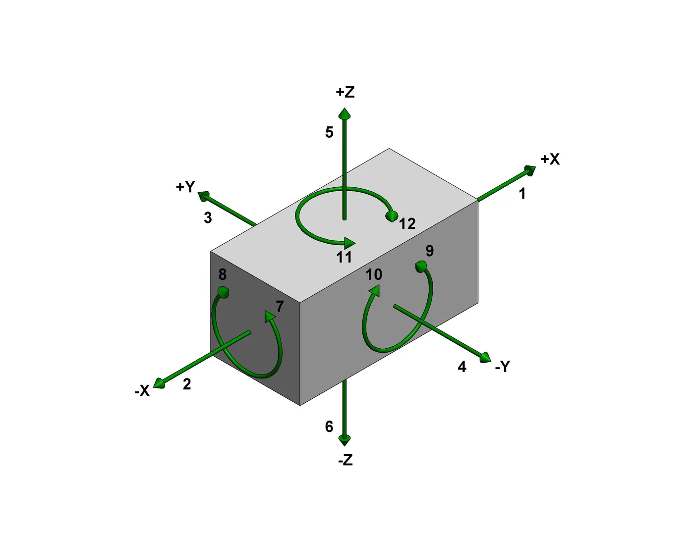
Fig 29:- Degrees of Freedom of a rectangular block
The Locating Process: 3-2-1 Method
We have two objectives when mounting a part in a fixture for machining:
- Accurately position the part at the desired coordinates.
- Restrict all six degrees of freedom so that the part cannot move.
A widely used method of accomplishing these two objectives uses the 3-2-1 principle, so-called because it entails three steps that employ three, then two, then one fixed points of known location. Since that adds up to six fixed points, it’s also known as the six-point method.
In the three steps of the 3-2-1 method, three mutually perpendicular planes, called datum planes, are introduced, one at each step. These three planes define the workpiece position, and together with opposing clamping forces fully constrain the part. Let’s take a look at the details of the 3-2-1 method.
To make sure the proper fixing of the part we need to restrict all 12 degrees of freedom of the workpiece. The major portion of the time of BIW fixture designer is spent deciding how to fix all DOF.
First Plane
Geometry tells us that three points are required to define a plane. This is the "3" in 3-2-1. So, three specific points are used to define the first plane. Fewer than three points cannot define a plane, and in the real world dimensional tolerances mean that four or more points will not be coplanar. A real-world, less-than-ideally perfect part placed on four or more reference points will rest on only three of the points due to its less-than-perfect surface. Different parts may rest on different combinations of three points, resulting in variation between finished parts. A stool can be used to illustrate this concept. A two-legged stool would certainly be unstable. A three-legged stool sits rock-solid. A four-legged stool is often found to rock. In the illustration, a three-dimensional part, represented by a cube, is placed on a datum plane defined by three support points. The part’s six degrees of freedom have now been reduced to three. It can still move along the X or Y axes, and it can still be rotated about the Z axis. (The part cannot move along the Z axis because it is held against the plane by clamping force.
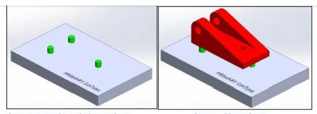
Fig 30:- 3-2-1 principle, Primary locator
Second Plane
A second plane, if it is perpendicular to the first, can be defined by two points, the "2" in 3-2-1. The part is now constrained to one degree of freedom: movement along the Y-axis (The part cannot move along the X or Z axes because it is held against the planes by clamping force.)
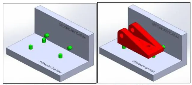
Fig 31:- 3-2-1 principle, Secondary locator
Third Plane
A third plane, if it is perpendicular to both of the first two planes, can be defined by one point, the "1" in 3-2-1. The part is now entirely constrained. It cannot move along or rotate about the X, Y, or Z axes. (Remember that the part is held against each of the three planes by clamping force.)
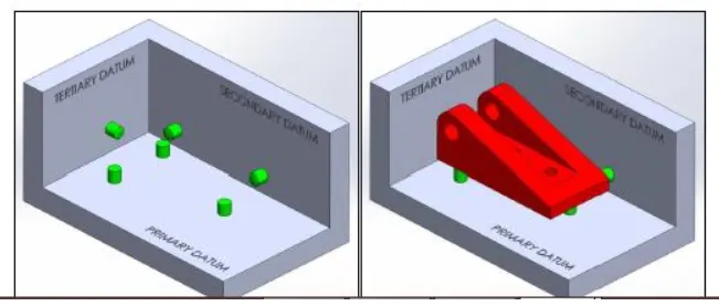
Fig 32:- 3-2-1 principle, Tertiary locator
Machined is Best
It’s best if the workpiece surfaces intended to contact the support points are machined. Cast surfaces are usable, but then tend to create tolerance problems. Machined holes are the number one choice. Two machined holes can be used to eliminate all but one degree of freedom.
Repeatability
Repeatability is a paramount concern. It means that each part should be nearly identical to the other parts coming off the same fixture. "Nearly identical" actually has a specific, quantifiable meaning: key dimensions of all parts produced on the same fixture must fall within defined tolerances.
To stay within tolerances, it’s best if the workpiece surfaces intended to contact the support points are machined. Cast surfaces are usable, but they tend to create tolerance problems. Machined holes are the number one choice because two machined holes can be used to eliminate all but one degree of freedom.
The next best feature to use for consistent locating is machined surfaces at right angles. The "machined surface" desired here can simply be a tab or small flat specifically included for locating purposes.
Repeatability is achieved through the application of the 3-2-1 method to the three aspects of the locating process:
- Supporting
- Locating (positioning)
- Holding
Supporting
The part is supported from "below" concerning the Z axis. (Introduction of the first reference plane.)
Gravity positions the part against the support locator.
Provide adjustable auxiliary support points as needed to prevent deflection.
Vertical location concerning the fixture is now established
The part is positioned horizontally, in the X-Y plane. (Introduction of the second and third reference planes.)
Holding
part is clamped against fixed locators. Therefore, a known and unvarying position of the part is maintained concerning the X, Y, and Z axes.
One strap clamp or clamp arm will restrict the workpiece in three dimensions due to friction between the workpiece and clamp. However, friction alone may not be enough to prevent the workpiece from moving during machining.
Cutting forces will not move a properly supported and clamped part.
Locating
The part is positioned horizontally, in the X-Y plane. (Introduction of the second and third reference planes).
5. Elaborate types of BIW Stations?
In the BIW assembly line, we have zones and these zones are divided into stations. These BIW stations are elaborated as follows:
The BIW stations are further divided into following
- Tool stations
- Gripper stations
- Stand station
- Miscellaneous stations
Tool stations:
The stations in which different tool processing is done fall into this category
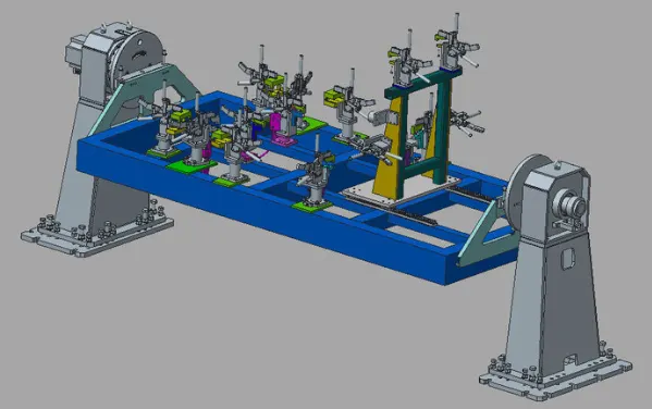
Fig 33:- Tool Station
Geo fixtures: This fixture is used to fix or assemble two or more parts. It can be either using welding or riveting. In this station precision and geometry of the finished product are defined Locating pins have a closer tolerance of 0/-0.15.
Suppose the hole dia of the panel is 16mm then the pin dia minimum can be 15.85.
The diameter of locating pins should be lesser than the panel hole dia. So tolerance in locating the pin is given in negative value.
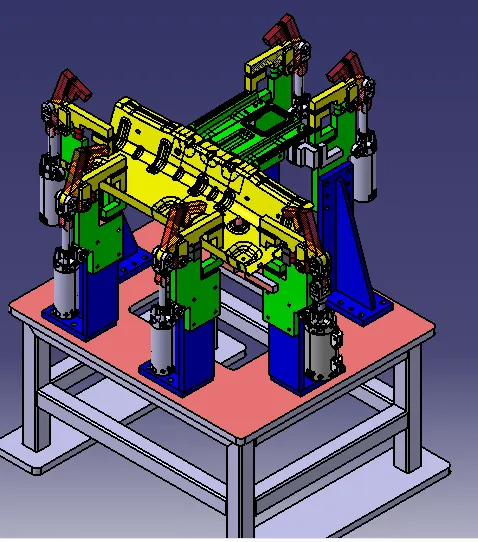
Fig 34:- Geo Tool Station
Re-spot fixtures: Once the product comes out of the Geo Station and there are left-out spots where spot welding or riveting is to be done. Then it is moved to another station, that station is called Re-spot station.
These left-out spots may be due to clamp plan, cycle time, robot reachability, or any other various reasons.
In this station pins have a tolerance up to 0/-0.28.
Marriage/Hemming fixtures: These fixtures are used for inner and outer panel assemblies. Since the joining of two parts happens in this fixture they are called marriage fixtures.
In this Station, inner and outer panels are joined. In this station to avoid the impression on the outer panel (A-class surface), copper strips are used in between the weld tip and the A-class surface.
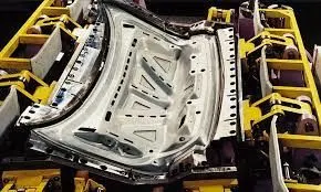
Fig 35:- Hemming Tool Station
Framer fixtures: These fixtures are used for joining the roof to the marriage fixture assembly output products. Since it makes a complete frame to the marriage component it is called a framer fixture
Checking Fixtures: These fixtures are used for checking and inspection purposes. No processing is done in these fixtures. These fixtures consist of gauges for checking the dimensions and tolerances and their accuracies. In some checking fixtures, fixtures are fixed and CMM devices check the geometrical accuracies
Grippers stations:
A gripper is a holding device that manipulates the object or moves the object from one place to another place. Gripper can be an end effector of a robot. It can be called the end of arm tooling.
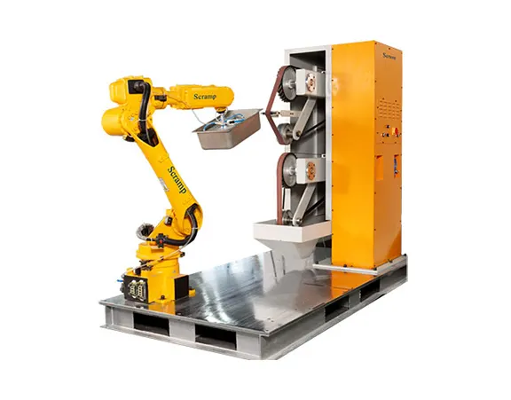
Fig 36:- Gripper
Material handling gripper: These grippers are used to handle materials from one station to another station.
Fig 37:- Material Handling Gripper
Process gripper: These grippers are used to handle materials from one station to another station and also help in completing processing. For suppose when the gripper holds the workpiece and moves along the glue nozzle gluing process will be done.
Fig 38:- Welding Gripper
Combo gripper: These grippers consist of holding equipment and processing tool equipment. This helps in obtaining a combination of holding and processing. Hence these are called combo grippers
Dual grippers: These are two-sided grippers. This helps in holding two workpieces at a time which saves a lot of time in the assembly line.
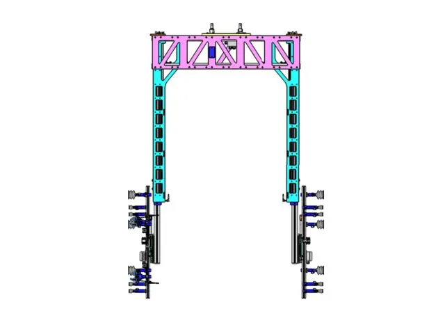
Fig 39:- Dual Gripper
Stand stations:
Stand stations are used to hold or mount the workpiece.
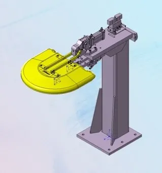
Fig 40:- Stand
Pedestal stand: These are fixed stands fixed on the ground permanently to which tools are attached. Such that the gripper can move along the stand to make the processing done.
Gluing and sealer stand: In this stand the gluing gun or sealing gun is attached and this stand is fixed permanently to the ground. In this station, Sealant application is carried out. This process can be carried out manually or by using robots. Sealer is used in between two panels so that panels do not flatter due to friction.
Docking stand: Robots have some limitations in their payload capacity or they may have to multitask, in such situations these docking stands help for giving temporary space or rest to the workpiece. Hence the robot can multitask or it can overcome payload limitations.
Date stamp stand: This stand helps to emboss the date of manufacturing or batch numbers or reference numbers on the parts.
Miscellaneous stations:
Curing Stand: These stands help in providing curing time for the assembly operations such as gluing or helps in cooling down the components after operations.
Fig 41:- Curing Stand
Buffer stand: These help in storing the components in this stand so that no overflow or lack of flow is not obtained in the assembly line. These create buffers in the assembly lines.
TTake-out trolleys: These trolleys are used to pull out the components from the assembly lines for inspection
Conveyors: These are rotating belts or chains which help transport the workpiece from one station to another station
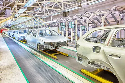
Fig 42:- Conveyor
6. What are the basic terminologies used in the BIW fixture?
Basic terminologies used in the BIW fixture
NC/Mylars/Fingers:- It is the component that holds the panel while operating. These are placed on the top side & the bottom side also. The top side of Mylars is called Clamping Mylars & the bottom side of Mylars are called Resting Mylars. Every clamping Mylar has resting mylar.
Principle locating point (PLP):- These are the points that are used for the accurate location of the part to maintain the geometry of the assembly. There are lots of holes on the panel which are not accurate due to the stamping operation. The PLP is defined in the drawing.
Risers:- Risers are of different types like L-typer rises, Square tube risers, etc. The riser is the manufacturing part that gives height to the assemblies.
Blade:- Blades are plates mounted on the riser. Other parts like cylinders, arms, etc are mounted on the blade.
Shims:- Shims are the small part that comes with a thickness of O.1mm, 0.2mm, 0.5mm, etc. These will compensate for the stack-up tolerance which reflects in the panel holding part called Mylars. We give tolerance to all the parts of the fixture. Due to this tolerance, the Mylars will either lift up or goes down from their defined position. If the Mylars goes down from the defined height it will make an impression.
Hardwares:- Hardwares are like Hex head bolts, Allen Bolts, Hex nuts, Spring washers, Self-locking nuts, etc.
CMM:- CMM stands for coordinate measuring machine. It is a device that measures the geometry of physical objects by sensing discrete points on the surface of the object with a probe.
Unit:- The fixture is the assembly of different types of units to form a fixture. There are different units like pin unit, base unit, clamping unit, etc.
Number plates:- The number plate is the aluminum embossed plate placed on each unit for easily recognizing the unit.
Nameplate:- The data like manufacturing company name, fixture type, Fixture weight, etc. is embossed on the plate & joined to the fixture.
Clamp Arm:- The clamp arm is part of the clamp unit which moves over an axis. Over the clamp arm, the Mylars are mounted.
Pivot:- It is an axis about which the clamp arm will rotate.
Class A Surface/Skin surface:- The outer panels of the car like the hood, door, backdoor, and fender. roof etc. are visible to the customer. The outer panels should be aesthetically very good. No, any scratches or dent is acceptable over it.
Reed switches & sensors:- These are the electric components used in automated fixtures. The reed switch is an electrical switch operated by an applied magnetic field. The detects whether the panel is loaded or not is done by sensors.