Week 1:- Introduction to BiW and Fixtures Challenge
- What is BIW & define its parts?
Ans:
Body in white (BIW) is the stage in automobile manufacturing in which a car body's frame has been joined together, that is before painting and before the motor, chassis sub-assemblies, or trim (glass, door locks/handles, seats, upholstery, electronics, etc.) have been integrated into the structure. Assembly involves different techniques such as welding (spot, MIG/MAG), riveting, clinching, bonding and laser brazing.
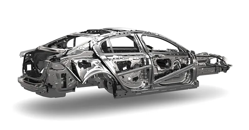
The term derives from manufacturing practices before steel unibody monocoques — when automobile bodies were made by outside firms on a separate chassis with an engine, suspension, and bumpers attached. The manufacturers built or purchased wooden bodies (with thin, non-structural metal sheets on the outside) to bolt onto the frame. The bodies were painted white prior to the final color.
A folk etymology for "body in white" is the appearance of a car body after it is dipped into a white bath of primer (undercoat paint)— despite the primer's actual gray color. BIW could also refer to when car bodywork would be made of timber - all timber products, furniture, etc are considered to be "in the white" when at the stage of raw timber before finishing or varnishing.
In car design, the "body in white" phase is where the final contours of the car body are worked out, in preparation for the ordering of the expensive production stamping die. Extensive computer simulations of crash-worthiness, manufacturability, and automotive aerodynamics are required before a clay model from the design studio can be converted into a body in white ready for production.
Factories may offer BIW cars to racers, who then may replace up to 90% of the car with aftermarket parts, and niche manufacturers like Ruf Automobile start their cars with BIWs from other makers.
BiW is expected to possess a number of significant properties. It must have high tensile strength as well as high stiffness—bending, torsional, static, and dynamic. It must also provide good quality safety both to the car body and to its occupants against crashes of all kinds—front, rear, side, or even rollover, meeting the Federal Motor Vehicle Safety Standard No. 208 . It should also be able to protect occupants from noise, vibration, and/or harshness (NVH) by absorbing or reducing these conditions. Also, it should be easy to weld and form, as well as be highly paintable and easy to design. It should provide a good surface finish that is smooth, and should also be corrosion resistant. Improvement of fuel economy also necessitates the use of lightweight materials in BiW, as it constitutes a significant share of a car's weight; in addition, given environmental concerns in recent times, it is also expected to be recyclable. Given such extensive requirements, only steel and aluminum have been used for making BiW; the former is preferred for its high strength and low cost, while the latter is preferred for its lower density that helps reduce car weight details the materials generally used for making BiW, along with their properties.
|
Material |
Yield Strength (MPa) |
Ultimate Tensile Strength (MPa) |
Reference |
|
Steel |
210–1250 |
340–1520 |
[46] |
|
Aluminum |
90 |
195 |
[47] |
|
CFRP |
250–585 |
[48] |
Amid the raging debate on the suitability of aluminum as a replacement for steel in BiW, a major transformation has occurred in the form of the entire BiW being made up of carbon-fiber-reinforced plastics (CFRPs) in BMW’s i3 model, a fully electric car . To study the suitability of CFRP as a material in manufacturing various car parts as well as its potential in lightweighting automobiles, BMW decided to produce a car with a main body completely made from CFRP, resulting in the production of BMW i3 at almost one-third of the market cost . CFRP was chosen for its lower density and higher specific strength when compared to both steel and aluminum.
The main body of BMW i3 consists of two modules—life module and drive module—with the former made entirely from CFRP and the latter made entirely from aluminum . Since batteries account for a significant share of an electric car’s weight and have to be recharged on a frequent basis, CFRP’s lower density helps lower the mass of BMW i3, thereby reducing the load on batteries and the requirement for their recharging . Moreover, low density and high specific strength of CFRP vis-à-vis steel mean that only 130 CFRP parts have to be joined together to constitute the car’s main body compared to an average of 400 steel parts per car . All these features have together meant that as per measurements conducted in Clemson University—International Center for Automotive Research (CU-ICAR), use of CFRP in BiW brought about a reduction of nearly 52% in BiW weight of BMW i3 compared to that of the MINI F56 model, a similar counterpart, highlighting the high potential for lightweighting cars through the use of CFRP.
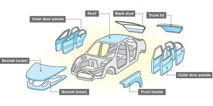
External components (front bumper, rear bumper, fender LH) / RH, side mirrors, etc.) can be attached to the BIW shell using various brackets or attachment systems. There are two types of BIW:
- Monocoque
- Body on frame
In Monocoque, all the members of the body are load-carrying and they are integrated with each other. Here the chassis is inbuilt with the BIW itself and there is no separate chassis. Wheels are directly mounted to the BIW with the help of a suspension system. Used in all passenger cars and to some extent in utility vehicles.
In a Body on frame, the body is placed on a frame which is the major load carrying member. The body is mounted on a separate chassis / frame and the wheels are mounted on the chassis, not the body. This type is used in commercial vehicles, trucks and buses.
Structure can be divided into following sub structures: -
- Under Body Structure
- Front End Structure
- Body Side Structure
- Closures
- Roof
An Under Body Structure: -
- Dash panel-provides partition between the engine and the driver cabin.
- FRT floor - provides base for seats.
- Raiser - connects front floor to rear floor by providing level difference.
- Rear floor - floor on the rear of the car and provides partition from ground and base for rear seats
- Rear wheel house
Front End Structure: -
- Plenum Panel- a chamber located b/w the throttle body and runners of the intake manifold.
- FRT wheel house (Fender)- is an encasement around the front wheel.
- Wing panel - outermost side panel in the front.
- Cowl -portion of the body bounded by the front fenders, the base of the windshield, and the rear edge of the hood.
- Upper tie bar -upper panel in front connecting the two sides of the front structure.
- Lower tie bar- lower panel in front connecting the two sides of the front structure.
Body side Structure: -
- pillar - front most support to the roof
- pillar - second support to the roof
- C/D pillar - c- is the rearmost support to the roof in case of a two row seating system, it will be the third one. D- is the fourth support usually rear
- side of the quarter panel.
- Ring panel - a structure panel connecting the rear and front portion.
- Quarter panel - rearmost panel of a body side structure.
- Drip rails / Gutters- an exposed channel applied to the roof over the side windows to direct water away from the windows.
Closures: -
- All doors
- Hoods/Bonnet -a hinged panel providing access to the engine compartment.
Roof Structure: -
- Roof
- Headers - structural member above the windshield at juncture with the forward edge of the roof panel.
- Bows
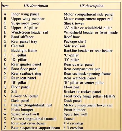
2. What do you understand by BIW nomenclature?
Ans: 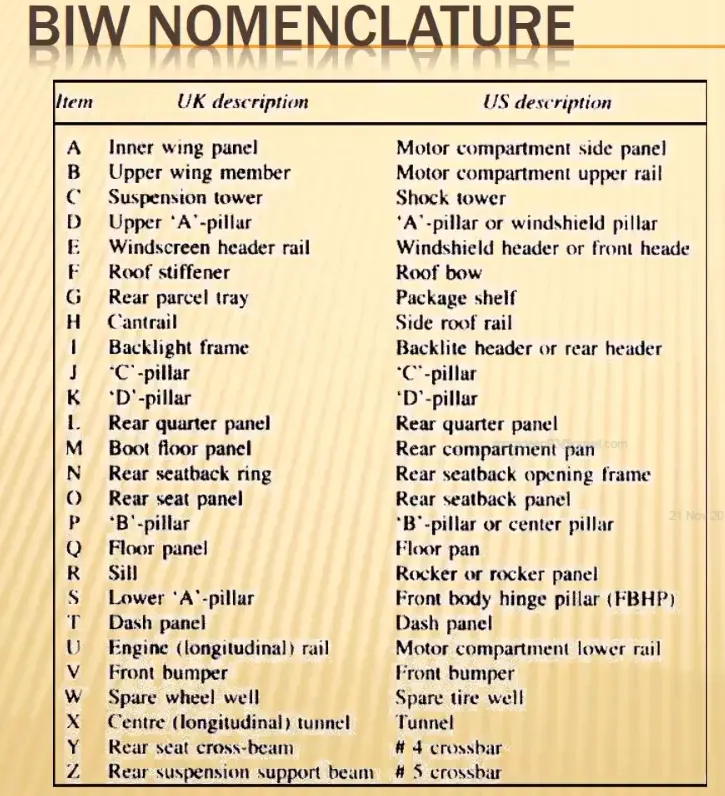
3. What is fixture & its types?
Ans:
A device which is used to hold, locate and support the component in the manufacturing industry is called a fixture. Fixtures provide stability to the part when any process is being done on that part. That process can be welding, riveting, grinding, drilling etc. In BIW fixture design Fixture works on 3-2-1 principle.the fixture is nothing but when separate parts seem to be joined we arrange those parts to their respective position to get a desired shape from all the parts .& that arrangement may be some height or an angle . So as a human being can not be holded that particular shape for a long time so that a machine or a equipment holding device called as fixture it holds the parts in the arrange shape for a certain time till the parts are welded together to obtain the desired shape. the fixture should have the capability to withstand the all the effect caused with the operation like when a welding operation is going on there will be lot of disturbing will be held like vibration,movements etc the fixtures should stable all the distortions created while the various operations.
In general fixtures are normally designed to hold & support the various components (work pieces) to be welded .it is necessary to support them in a proper location which is capable of preventing distorations in the workpiece during welding .for this the locating elements need to be placed carefully. clampin hsas to be light but firm. placement of clamping elements hasto be clear of the welding area the fixture hasto be quite stable & rigid to withstand the welding stresses.
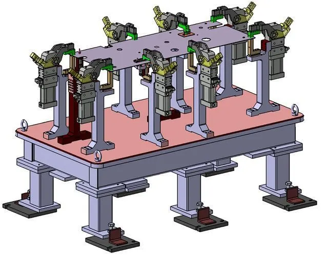
THE TYPES OF FIXTURES.
- PRODUCTION FIXTURES
- PRE PRODUCTION OPERATION FIXTURES (PPO)
- CHECKING FIXTURES.
PRODUCTION FIXTURE-
Production fixture is used in mass production.This fixture used to hold the car body assemblies till the end part processing at that particular machine .The fixtures used here should have good quality. It should have good tolerances,rigidity, & also good maintenance after a certain amount of time. The production fixture can be easily assembled & dis-assembled throughout the required time.
PRE PRODUCTION OPERATION FIXTURES-
This type of fixture is used for initial batch production and to study the feasibility.it is the base fixture in production that is used to check the feasibility, inspection purpose to rectify the errors of the body . In this pre production stage there will be a lot of manual inspection will be done so that there can be some distortion in between so that this type of fixtures should be stand & stable. In this stage the engineers & quality members will work on the body to inspect & to verify the errors and issues in the body. This stage has larger time-consuming process base fixtures. for designing the production fixture. the fixtures which are designed should be less costly.
CHECKING FIXTURES-
Used for car panel geometric inspection purposes.
after completion of all the operations related to joining, then next comes to this checking fixtures stage here with the help of gauges inspection will be carried out ,styling, design , assembling positions etc.checking fixtures as the same geo fixture except there no operation done like welding,gluing, orhemming. Instead it will use different in-built gauges or external gauges to check various dimensions,gaps,relative dimensions,tolerances; these data are compared with data provided by the designer or design team . The geometry of the welded part is also checked in this stage fixture to ensure the part maintains the required dimension & geometry.
4.What is the basic principle of fixture design?
Ans:
3-2-1 Principle
- The 3-2-1 method is a work-holding principle where three pins are located on the 1st principle plane, i.e., either XY, YZ, ZX. And two pins are located on the 2nd plane perpendicular to the 1st plane, and at last, one pin on the plane is mutually perpendicular to the 1st and 2nd planes.
- It represents the minimum requirement for the locating elements.
- The locators along with the clams which hold the part in place, provide equilibrium for all the forces.
- Stability is satisfactory if all three rest buttons are widely spaced and the resulting cutting force lies within the triangular area between the buttons.
- If the resultant cutting force lies outside the triangular area then it generates a moment which in turn lifts or overturns the component.
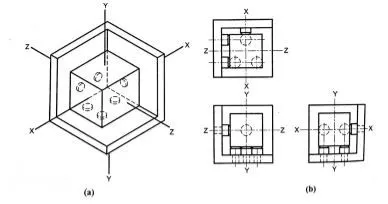
Degrees of Freedom
There are 12 degrees of freedom of a workpiece, movement about the negative and positive axis and clockwise and anti-clockwise rotation about the three axis.
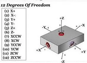
There are 6 translational degrees of freedom +X, -X, +Y, -Y, +Z, -Z,
6 rotational degrees of freedom which are
- Clockwise around X axis (CROT-X)
- Anticlockwise around X axis (ACROT-X)
- Clockwise around Y axis (CROT-Y)
- Anticlockwise around Y axis (ACROT-Y)
- Clockwise around the Z axis (CROT-Z)
- Anticlockwise around the Z axis (ACROT-Z)
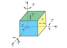
We must fix all the 12 degrees of freedom except the three translational degrees of freedom (-X, -Y and -Z) in order to locate the work piece in the fixture. So, the 9 degrees of freedom of the workpiece needs to be fixed.
The jig and fixture are tools used for holding the work piece in a correct location for mass production. Various types of fixtures (like drilling fixtures, milling fixtures, and welding fixtures) are used in industry. The 3-2-1 method is the fundamental principle for all types of fixture design.
5.Elaborate types of BIW Stations?
Ans:
In BIW fixture designing we have various stations which are used to locate the panels so that joining processes can be done.
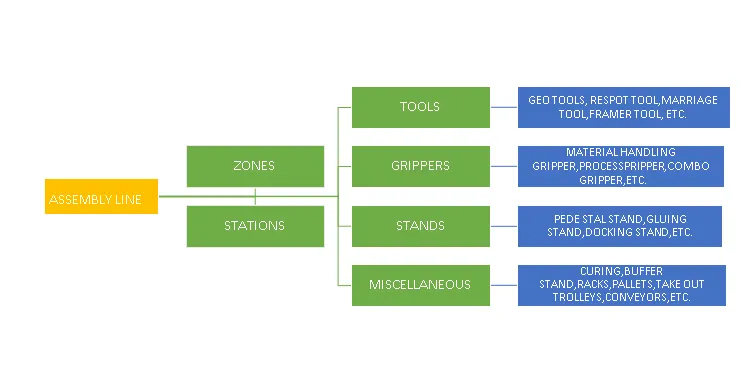
Some of these stations are as follows
- Geo Station
- Respot Station
- Pedestal Weld/Rivet
- Loading Station
- Buffer Station
- Marriage station
- Sealing station
- Curing station
Geo Station
In this station geometry of two parts is fixed. It can be either using welding or riveting . In this station precision and geometry of the finished product is defined: Locating pins have a closer tolerance of 0/-0.15.
Diameter of locating pins should be lesser than the panel hole dia. So Tolerance in locating pins is given a negative value.
Respot Station
Once a product comes out of the Geo Station and there are left out spots where spot welding or riveting is to be done, it is moved to another station.
This station is called Re-spot station.
These left out spots may be due to clamping, cycle time,robot reach ability or any other various reasons.
Checking Station
A Checking station is the place where all the features such as positioning, tolerances, and relative dimensions of a component are checked.
A CMM machine is employed to check these parameters and gives a proper report with respect to the nominal values.
Pedestal Weld/Rivet
In this station , the Pedestal gun is mounted on a tool and the panel is manipulated manually or by robot to weld the panels.
Pedestal station is generally a Re spot station.
Re spot station and Pedestal station both perform the same kind of operation . But to decide whether to go for a pedestal or a re-spot station some parameters need to be considered like cycle time, floor space, no. of welds, clamp plan, or size of the panel.
Loading Station
This station is used for loading panels and the same station is used to change the orientation if it is required in the upcoming station.
Sometimes this station is used when Robots are unable to transfer panels from one station to another.
Buffer Station
This station is used to make the balance between the process.
Some stations carry out the process in less time as compared to their respective stations.In that case panels can be stored in one station so that the assembly line process remains smooth.
Marriage station
In this Station inner and outer panels are joined.
In this station, to avoid the impression on the outer panel(A class surface), copper strips are used in between the weld tip and A-class surface.
Sealing station
In this station Sealant application is carried out.T
his process can be carried out manually or by using robots. Sealer is used in between two panels so that panels do not flatter due to friction.
Curing station
In this Station, product received after sealing application is kept idle at ambient temperature, which allows sealant to get dry with better bonding between the panel.
6. What are the basic terminologies used in the BIW fixture?
Ans:
- A class panel-Generally exterior sheet metal components have A-class surfaces. A class surface plays an important role in the overall styling of automobiles. A, B class surfaces depend on the degree of the curves. Most of the product designers work with various styling software e.g.ICSM Surf, Alias to design free-form design panels. Class panels eg. LH/RH bodyside, Doors, Tailgate, Bonnet, Fenders and Roof
- Spot Welding- It's a type of resistance welding .2/3 sheet metals are joined together
- 2 Metal Spot- Resistance spot welding to join sheet 2 metal parts
- 3 Metal Spot- Resistance spot welding to join sheet 3 metal parts
- Carlines- All the BIW product design and BIW fixture/ tool designer, BIW process planner and BIW simulation Engineer have to know car lines. To represent the position of biw car parts,welding fixtures and its unit assemblies with its individual parts (e.g.mylars) in 2D drawings, their respective positions are shown with reference to (X=0,Y=0,Z=0)positions. In short its shows in 2D XY, YZ or XZ coordinate position of BIW welding fixture parts or assemblies with reference to origin X=0,Y=0,Z=0
- Mylar: Called a Rest or Clamp block which is used for holding 2/3 BIW sheet metal parts.Mylars are also called NC blocks. In German, Mylar is called a counter stein. Mylars plays an important role in BIW welded assembly geometrical accuracy. Mylars are made of steel or in plastic material.
- Rest Block : As per the 3-2-1 principle to rest any part/ assembly 3 points are required. Generally, rest blocks are provided and adjusted by providing shims.
- Clamp block : Generally as per the 3-2-1 principle for holding the component the clamp block is moved via toggle clamp against the rest block PLP- Principle Location point
- RPS- Reference Punkt System. Same as PLP
- Location Round Pin- Pin used to locate BIW sheet metal parts.Also called 4-way pin.
- Diamond Pin- Pin having diamond shape in top view.Used to restrict only 2 direction.Mostly referred as 2 way pin.
- Shim solid- Generally for the Mylar and Locating pin adjustment solid plate of 5 mm thk with various sizes is used. Generally a solid shim of 2 slot, 3 slot or 4 slot.
- Shim Pack - Generally for the Mylar and Locating pin adjustment, a solid shim pack is used. the 5 mm thk shim pack has various options of 0.5mm x2, 1mmx2, 2mmx1 to make a shim pack. Shim is of 2 slot/ hole, 3 slot/hole or 4 slot/hole