Week 1:- Introduction to BiW and Fixtures Challenge
1) What is BIW & define its parts?
- BIW or better known as Body-In-White refers to the stage in the manufacturing assembly of a vehicle where the sheet metal components are welded to form the vehicle structure to which the other various components are assembled onto.
- This is the stage that comes after the welding of the various panels are done to form the body structure and before the painting is done.
- It is known as Body in White since before the body is painted, the body goes through a primer bath and when it does come out of this bath, the body is actually grey in colour and hence, for ease of reference, we call this structure Body in White.
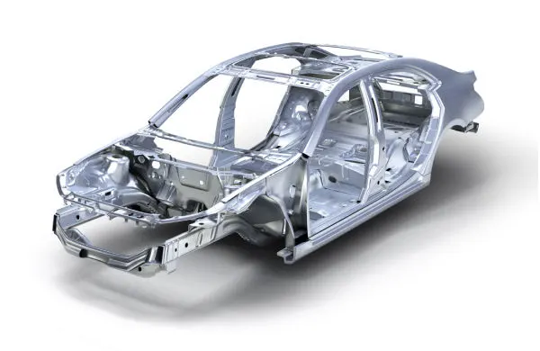
The various components and their sub components are listed below:
- Body Side – Body Side Outer, Body Side Inner
The body side refers to the general body of the vehicle to which the other BIW components are fixed. There are 2 components to consider here, that is, the Body Side outer panel, which is what we as a customer will see and the Body side inner, which is the panel that will sit inside the outer panel.
- Under Body – Front End Under Frame (Engine Compartment), Main Floor, Rear End Under Frame
The underbody or the bottom most section in a vehicle, which includes your vehicle floor and also the sub-assemblies which hold the components in the engine compartment and the same goes for the rear section of the vehicle with its rear sub-assemblies.
- Closures – Front Doors, Rear Doors, Hood, Boot Lid
Closures refer to the sheet metal panels that will be fixed to the body side and will be the opening and closing panel, with the help of a hinge mechanism, on the vehicle.
- Roof – Roof Outer Panel, Roof Inner Panel
Roof is a sheet metal panel that is used to close the body of the vehicle on its top side.
- Fender
The fender is another component that comes above the wheels of the vehicle, it houses the wheel arch and also protects the engine compartment from the sides.
2) What do you understand by BIW Nomenclature?
BIW Nomenclature refers to the system of naming the various components of the BIW structure. Since there are a multitude of components in a BIW structures, it is important that they all should be named, for ease of manufacturing and construction.
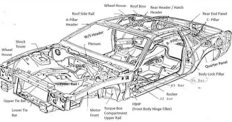
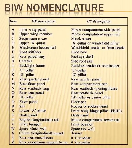
The BIW nomenclature is not standardized world over and it varies slightly from region to region. For example, the image attached below shows how the nomenclature of the BIW components varies from the UK and US regions. The image below verifies the previous statement.
3) What is fixture & its types?
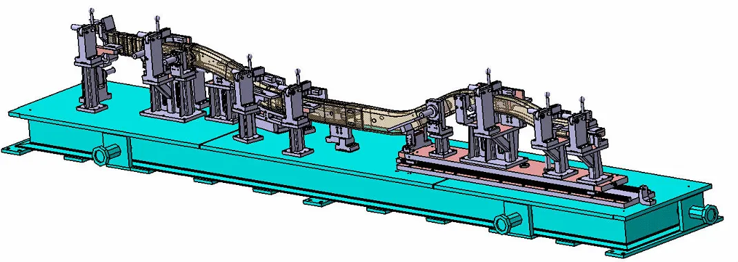
A fixture is a device that is used for locating, supporting and holding a workpiece during the manufacturing or assembling process. Fixtures are essential elements of production processes as they are required in most of the automated manufacturing, inspection, and assembly operations.
Fixtures are normally designed to hold and support and the various components to be welded. The fixture is necessary to support them in a proper location which is capable of distortion in the component during the welding process. For this very reason, the locating element needs to be placed carefully, the clamping has to be firm to hold the component in place, but light enough that it does it not damage the panel when it is being welded together. One very important factor to consider is that the fixture must be clear of the welding area and it should be rigid enough to handle the stress caused due to the welding process.
Types of Fixtures:
Fixtures are mainly classified into 3 categories:
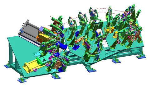
- Pre-Production Operation Fixtures
It is designed as a prototype fixture for initial batch production to study the feasibility and if anu changes or modifications must be done for the final production fixtures. It helps set the benchmark and criteria and help in rectifying the possible errors that could come in the production fixtures. In pre-production there will be more human intervention along with manual quality checks and this will lead it to have a larger cycle time than in the case of a final production fixture.
- Production Fixtures
These are the type of fixtures that is used for mass production purpose and in the final assembly line. The pre-production fixtures set the benchmark and requirements the final production fixtures should have. The material and construction of the fixture is also tested in the pre-production phase and hence the production fixture will be the most ideal fixture for that use case and that can run on minimal human intervention.
- Checking Fixtures
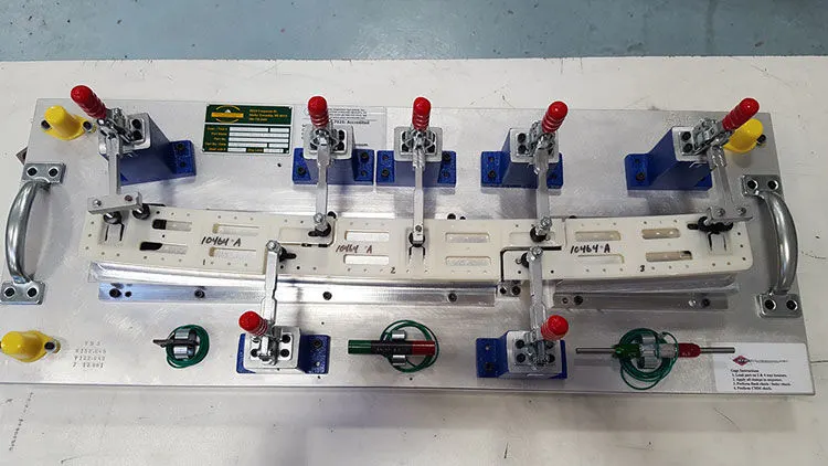
Checking fixture, as the name suggests, is simply to inspect an assembly. These fixtures do not do any type of operations on the component such as welding, gluing and such, instead gauges are used, built into the fixture or an external ones are used to measure gaps, tolerances and dimensions. This data is cross verified with the data that is provided to the team to check if the component has maintained all the said dimensions and tolerances and if the welds have been done at the right spots.
4) What is the basic principle of fixture design?
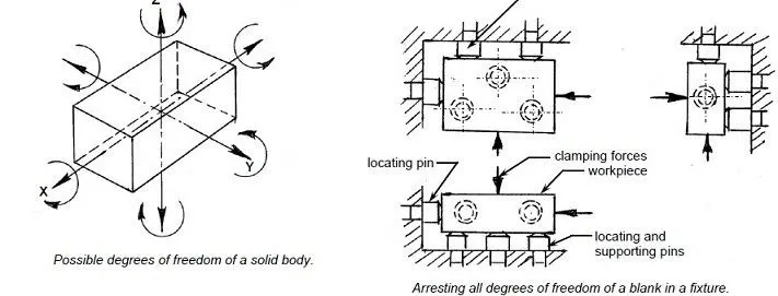
The basic principle of fixture design is to hold the body firmly enough to prevent it from about moving about any of its degrees of freedom. Every body has 12 degrees of freedom inherently, these are the 6 translational degrees of freedom and 6 rotational degrees of freedom.A good fixture will prevent the body from moving about any of these 12 degrees of freedom and thus provide the body with 0 degrees of freedom.
The 3-2-1 principle of location is used to constrain the movement of workpiece along the three axes XX, YY and ZZ. This is achieved by providing 6 locating points, 3 pins in base plate, 2 pins in the vertical plane and 1 pin in a plane which is perpendicular to the first two planes. The degree of freedom is the defines the ability of a body to move. Every body has 12 degrees of freedom or 12 possible movements and these twelve are broken down into 6 translational degrees of freedom and 6 rotational degrees of freedom. The 3-2-1 method is the fundamental principle for all types of fixture design.
Consider a body in a 3 axis coordinate system where we have the X,Y & Z as the respective axes. The image below shows the body in this coordinate system
From this we can infer that the 6 translational degrees of freedom are about:
+X, -X, +Y, -Y, +Z, -Z.
The 6 rotational degrees of freedom:
- Clockwise about X-axis (CROT-X)
- Anticlockwise about X-axis (ACROT-X)
- Clockwise about Y-axis (CROT-Y)
- Anticlockwise about Y-axis (ACROT-Y)
- Clockwise about Z-axis (CROT-Z)
- Anticlockwise about Z-axis (ACROT-Z)
5) Elaborate Types of BIW Stations
BIW stations are generally classified as :
- Tool Stations
- Gripper Stations
- Stands
- Miscellaneous Stations
A few noticeable examples of the various stations are listed below.
Tool Stations
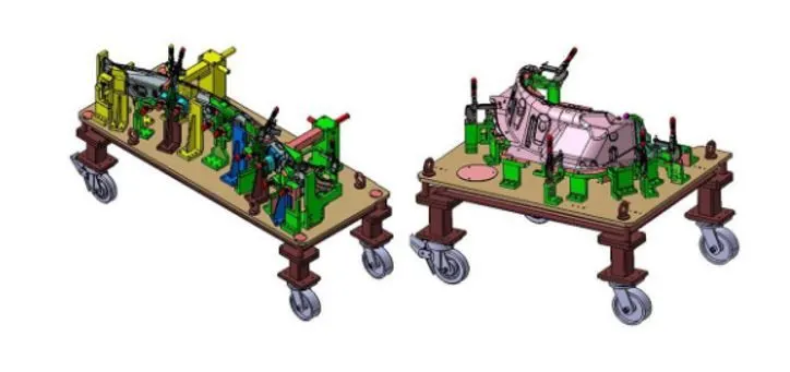
- Geo Fixture: Geo fixtures are fixtures that are used to weld components in the assembly with a extremely precise accuracy. It can be noted that a geo tool has a very low tolerance of +/- 0.02mm and the positional pin tolerance of 0.15 for this very same fact. The geo fixtures will generally give the initial few extremely accurate welds to give definition to the geometry of the assembly.
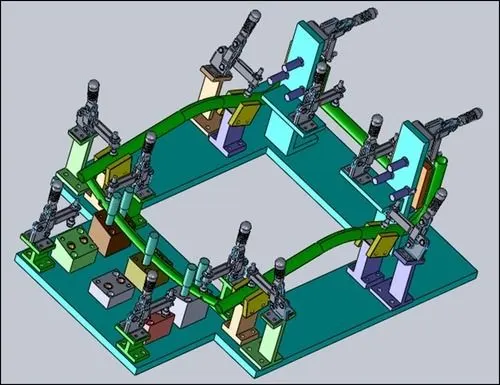
- Re-Spot Fixture: Like the geo tool fixture, the respot tool is also used to weld the assembly at the required defined areas. The difference is that, a geo tool will give the first few important welds to give the assembly it's required geometry but the remaining welds that are to be given to the assembly are provided with the re-spot tool. The re-spot tool has much higher tolerance than the geo fixture tools. This kind of a setup is done so that one station does not get held up with one assembly by providing it with its various welds, rather the more important and defining welds are given in the geo fixture station and then the assembly is moved to the re spot fixture so that its orientation can be changed if necessary for the remaining welds.
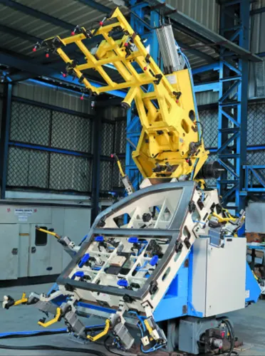
- Marriage Fixture: As the name suggests, this tool is used for the marriage/joining of components. This is the station were joining processes such as hemming, gluing, welding and riveting is done to join the various inner panels to their respective outer panels. The side doors, hood, underbody and back door assemblies are common examples of assemblies that are joined together in this station by the above said processes.
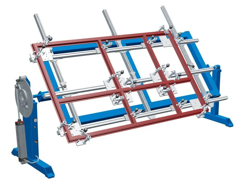
- Framer Fixture: This is the station that usually follows the marriage tool, in this station the output of the marriage tool is attached to another component to finally form its framework. Hence this is known as the framer tool.
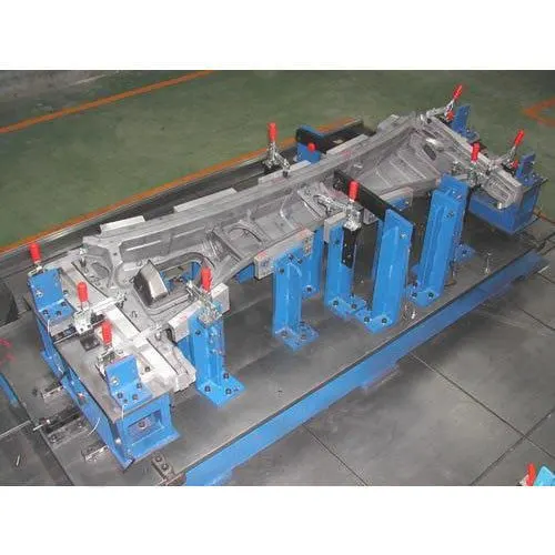
- Checking Fixture: A checking station tool fixture is a fixture which is used to check and ensure that all the coordinates, relative dimensions and positions as per the tolerances. A checking fixture can be a gauge type, fixed type or an automated checking fixture.
Grippers
A gripper is a device that is used to manipulate or hold onto an object in the assembly. These grippers help in holding, releasing of the various components. The gripper is attached to the end of a robot arm in the assembly line and this setup mimics a human arm and how it would function.
There are various types of grippers that are used in the industry and some of the commonly used ones are listed below:
- Material Handling Gripper: The material handling gripper as the name suggest, will move the required material from one station to the next.
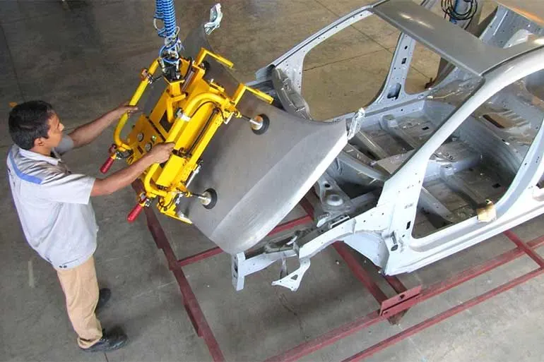
- Process Gripper: The process grippers are designed to pick the assembly and move it various fixed pedestal stands. These pedestal stands will be placed for various processes such as gluing, riveting etc. So, when the process gripper picks the assembly, moves it to the pedestal stand and orients the assembly the right way so that the required process can be done on the pedestal stand and the panel can be moved to the next stand.
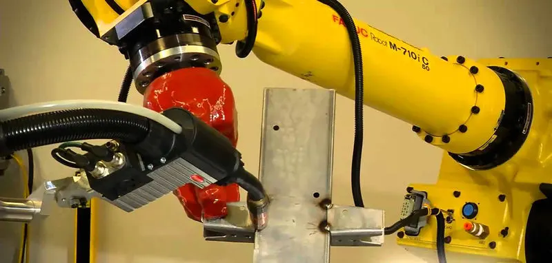
- Combo Gripper: A combo gripper is a type of gripper where the gripper moves the assembly from one station to another and in tandem with this process, the gripper will have an additional attachment such as a weld gun for example, which ensure that the gripper itself can move the component and conduct the process on it.
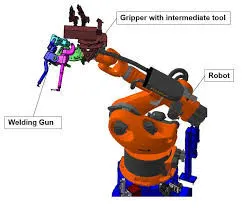
- Dual Gripper: Dual gripper is similar to a material handling gripper, it is used to move assemblies from one station to another but in this gripper, it has 2 grippers so that it can hold multiple components together at the same time. This is done in case where 2 panels need to be brought together in symmetry to be assembled such as a car side body.
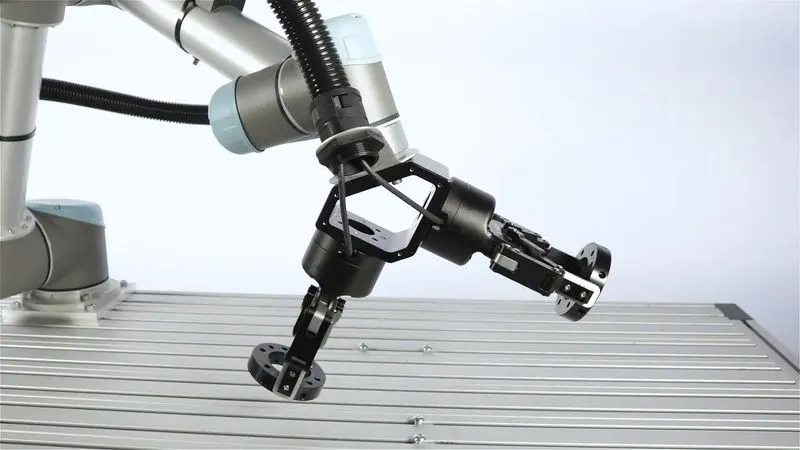
Stands
A stand is nothing but a fixed supporting element which will have a robotic arm attached to it and this robot will have a tool of some sort fixed to it. There are a few different types of stands used in the industry and they are:
- Gluing and Sealer Stand: In this stand, a gluing or welding gun is attached to a standard stand which will be welded or fixed by some other means to the floor. It is fixed in such a way so as to avoid external factors such as the vibrations of other machinery do not cause errors in the accuracy of the process being done on the workpiece.
- Docking Stand: A docking stand is used specifically for when a robot arm which is doing multiple operations such as handling the material as well as welding it for example, and the robot cannot carry them due to the combined weight of the workpiece and the tool exceeds the payload capacity of the robot arm then the robot will move to the docking stand and drop its gripper and then attach the welding gun in place. The docking stand acts as a unit where the robot arm can dock its tool and switch to the required tool when it cannot handle the load.
- Date Stamp Stand: This is a stamp stand where the required date is stamped on to panel or assembly. The gripper will bring assembly to this stand and then the stand will stamp the date on to the panel at the required position.
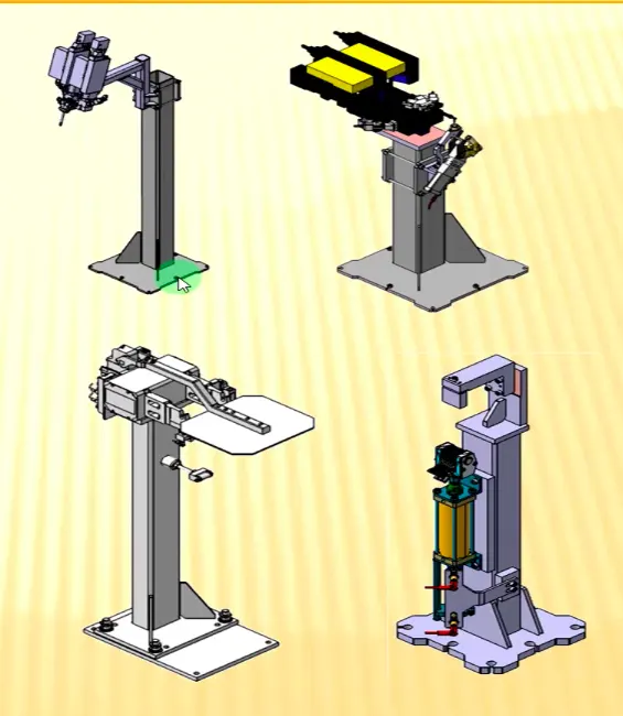
The image above shows a few examples for the stands used in a BIW assembly line.
Miscellaneous Stands
- Curing Stand: These are stand that are used to keep the assembly after the curing process is done when the workpiece would require to be cooled down and will need to be safely kept till this is done.
- Buffer Storage: A buffer storage is a stand where multiple components can be placed on it so that it can be kept away till required later in the assembly and this is known as buffer stock. This is also done when that particular station is undergoing some sort of maintenance, that part that is being worked on in that particaular station can be wroked on and kept on a the buffer storage so that when the assembly of that other parts is being worked on, there will be no delay in the assembly line as one station is under maintenance.
- Conveyor Stands: Its a chain or belt driven conveyor belt on which the aseembly or panel can be fixed on and the panel can be taken through the conveyor assembly. This is usually done for inspection of the workpiece.
- Takeout Trolley: Take out trolley is used to take the car panel out of the robotic working cell between the operation cycle for inspection purposes.
6) What are the basic terminologies used in BIW fixtures?
- Mylars/Fingers/NC: Mylars are the components in the fixture that holds the workpiece from top and bottom. The mylar on top is called the clamping mylar and the one at the bottom is known as the resting mylar. Every clamping mylar will have a resting mylar.
- PLP: Principle Locating Point are specifically mentioned point or holes in the workpiece which are used as reference to maintain the geometry and orientation of the workpiece. Since there are a multitude of holes in the workpiece, these PLPs will be mentioned by the designer in their 2D drawings.
- Blade: Blades are plates that are attached to the risers and these plates will have holes provided on them so that the other components such as the cylinder and such can be mounted onto the fixture.’
- Risers: Risers are used to provide an additional height to the assembly. Risers come in many types such as a L type riser, welded square to frame type etc.
- Shims: A shim is nothing but a thin plate that is used to adjust the height of a component. When it comes to manufacturing an assembly, there tends to be a stacking of the various tolerances and this will cause a misalignment in the case of a Mylar. The mylar will either be gripping the workpiece too firmly or it will not be able to hold the workpiece properly depending on if the stacked up tolerance is positive or negative. This is where the shim comes into play, the shim can be used as a spacer on the mylar to adjust its height so that it can adjust to this tolerance build up. Shims come in multiple sizes such as 0.1mm, 0.2mm and 0.5mm for ease of usability.
- Rough Locators: Rough locators are used as guides for the manual operator to place the assembly in the correct orientation. This is only done for manual loading and these locators are placed in a way so as to prevent the panel from placed wrongly.
- Hardwares: Hardware refers to the bolts, nuts and other fasteners that are used in the assembly
- CMM: CMM or Coordinate Measuring Machine is used to check the coordinates of a fixture or an assembly as per the CAD data that was provided to ensure that there are no errors in the assembly.
- Units: Units in this case refers to the sub components in the fixture. A fixture is basically an assembly of various units which form the fixture such as a base unit, pin unit, clamp unit etc.
- Number Plate: Number plate is an aluminium embossing that is pasted onto each unit to help in the identification of the various units in the fixture assembly.
- Coordinate Plate: These plates will contain holes and the coordinates of the holes will be mentioned.
- Name Plate: Name plate is plate that will fixed to the fixture assembly that will contain the basic info of the fixture.
- Clamp Arm: The unit in the fixture which is responsible for the movement of the clamp unit is called the clamp arm.
- Pivot: Pivot is the unit in the assembly about which the clamp arms motion or movement is based about.
- Class A Surface: The class A surface is nothing but the surface of the final assembly that is visible to the end customer, in essence the outer shell/panel of the product. This component should be the most visually aesthetic part in the final product and hence this part should be handled with extreme care so as to not damage it in any way.
- Reed Switches: Reed switches are magnetic read sensors that are mounted on the cylinder. These are used to locate the position of the piston in the cylinder.
- Sensors: Sensors are used to detect the placement of the part or if the part has been loaded onto the fixture. There are variety of sensors used in an assembly such as a proximity sensor, pressure sensor etc. Sensors are used mostly when the assembly is automated.