Week 1 : Exploring the GUI of GT-POWER
GT-SUITE is the industry-leading simulation tool with capabilities and libraries aimed at a wide variety of applications and industries. It offers engineers functionalities ranging from fast concept design to detailed system or sub-system/component analyses, design optimization, and root cause investigation.
ALL PHYSICS LIBRARIES WITH GT-SUITE
The foundation of GT-SUITE is a versatile multi-physics platform for constructing models of general systems based on many underlying fundamental libraries:
- Flow library (any fluid, gas or liquid or mixture)
- Acoustics library (both non-linear and linear)
- Thermal library (all types of heat transfer)
- Mechanical library (kinematics, multi-body dynamics, frequency domain)
- Electric and Electromagnetic library (circuits, electromechanical devices)
- Chemistry library (chemical kinetics)
- Controls library (signal processing)
- Built-in 3D CFD and 3D FE (thermal and structural)
Advanced Features
- Fast solver makes simulations of large systems practical
- Distributed computing
- DOE and optimization
- Fusion of 1D and 3D simulation in one tool
- Imports solid models from CAD to create 1D and 3D models
- Performs embedded 3D CFD and 3D FE thermal/structural modeling with all boundary conditions provided by the simulated surrounding complete system
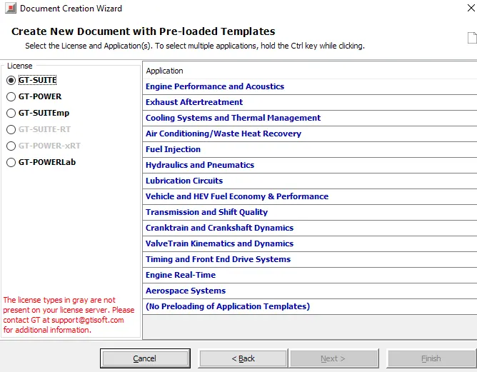
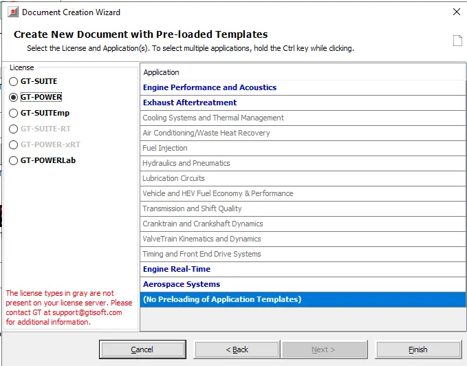
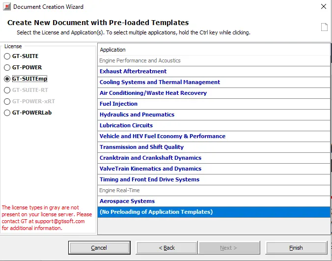
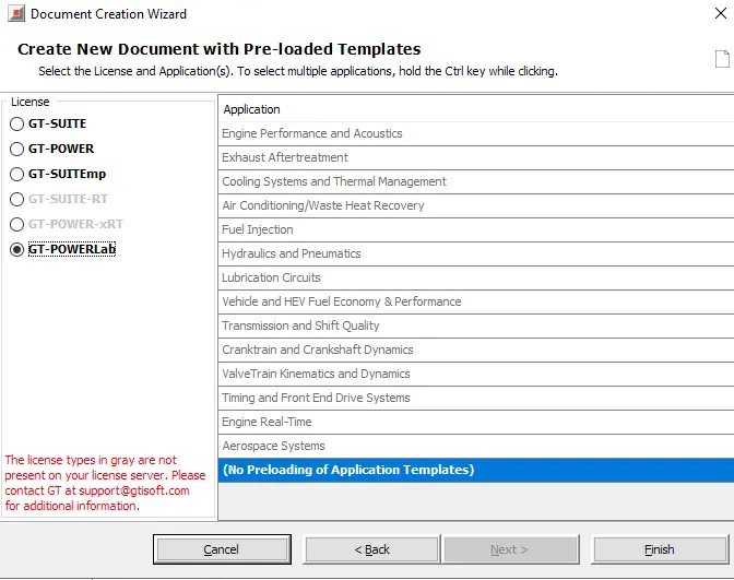
Vrious types of licences:
GT-SUITE
GT-POWER
GT-SUITEmp
GT-POWERLab
Idetifying the particular settings:
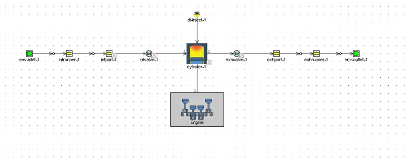
From Tutorial, Single cylinder direct injection diesel engine module is opened and analyzed.
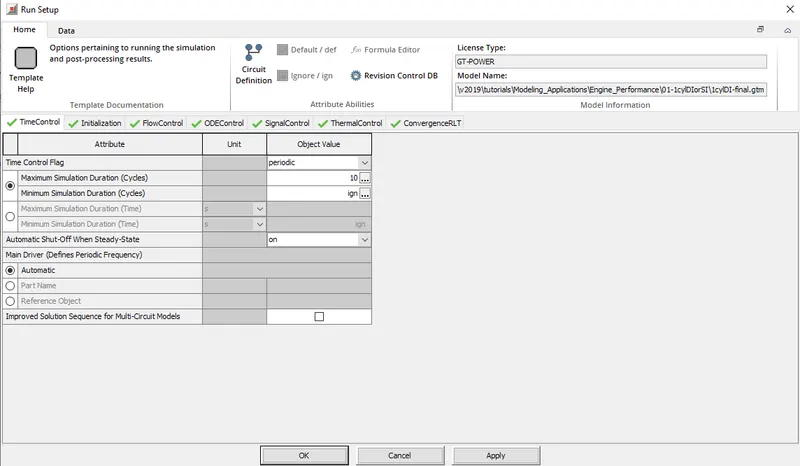
Time control Flag
It is present in the TIme control tab of the Run Setup
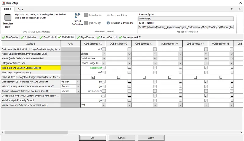
Time step and solution control
It is present in the ODEControl tab of Run Setup.
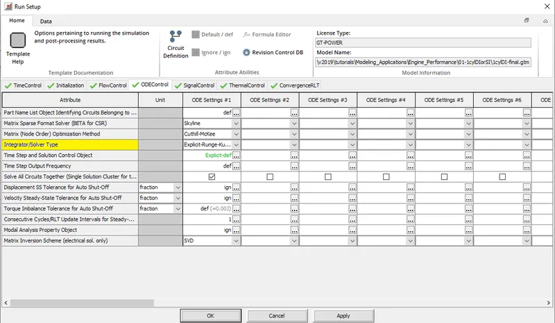
Integrator/Solver type
It is present in the ODEControl tab of Run Setup.
Explore intercooler tutorial and note down all settings of:
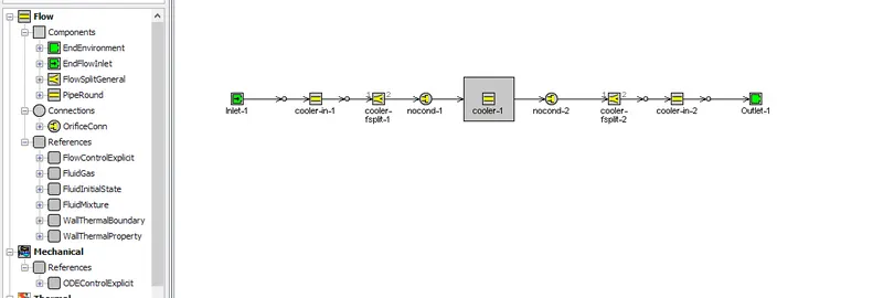
The intercooler tutorial looks like the following
- Run setup
It contains various settings related to the running of the solver.
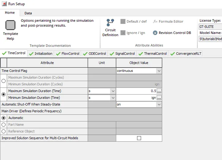
Time control: It control the type of time simulation setting and the minimum and maximum simulation time settings.
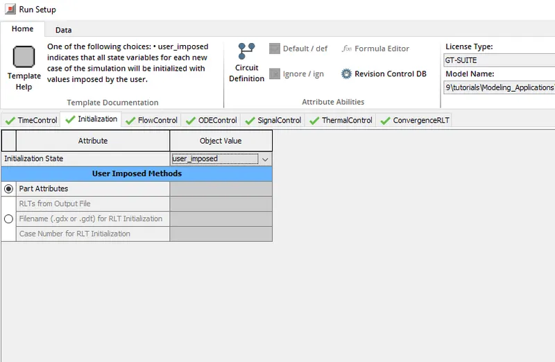
Initialization: It controls the settings for initializing the simulation and seelcting the type.
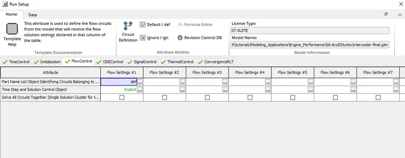
FLow Control: It conains the settings of the solver to be used i.e. either explicit or implicit.
ODE-Control: It gives user settings to choose a solver type, various optimaztion methods for running the solver etc.
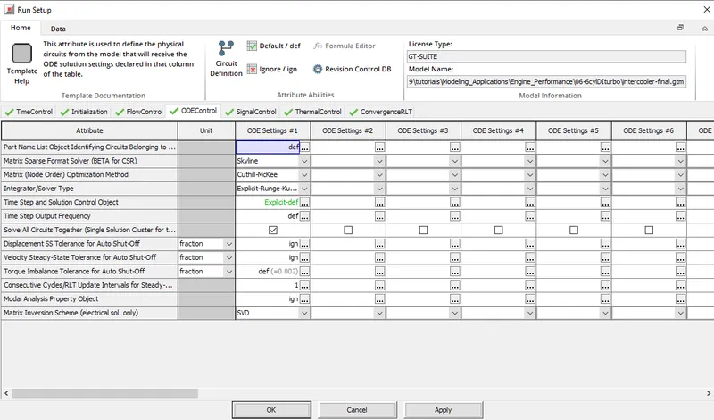
Thermal Control is used to control settings related to stready state tolerance, threshhold control etc and while Convergence control sets the various convergence parameters which play essesntial role during the simulation.
- Advanced setup
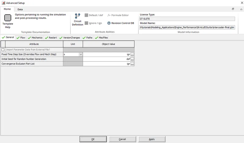
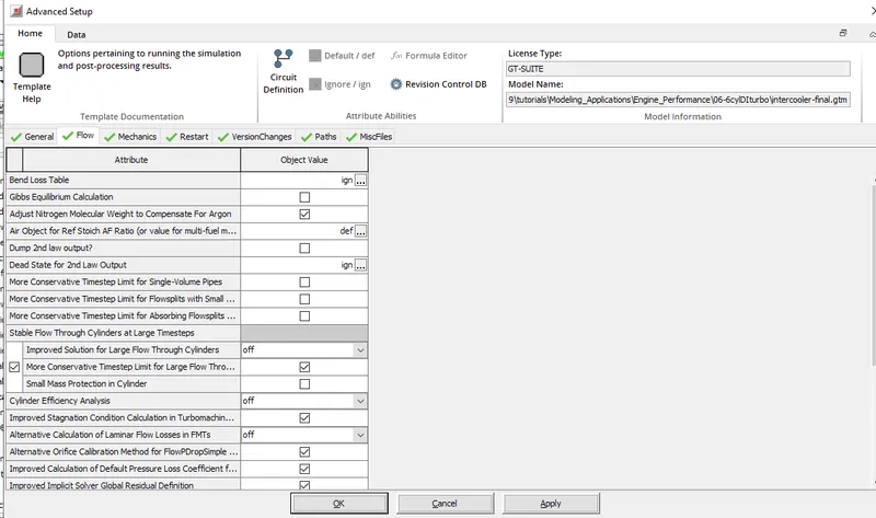
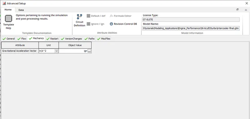
It contains some of the input parameters which are left untouched in the norma RUN setup tab and are not always changed or modified.
General:
Flow:
Mechnaics:
- Plot setup
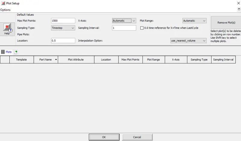
Cycle and/or time plots may be requested by selecting the appropriate plot from the "Plot Options" folder within each part. Each of these requests will result in a plot being stored. (This is not true when the specific plot requires a certain modeling option to be used in order to calculate the results that are to be presented in the plot. For example, plots of the pipe wall temperature versus radius will be made only when the wall temperature solver is used in the model.)
- Output setup
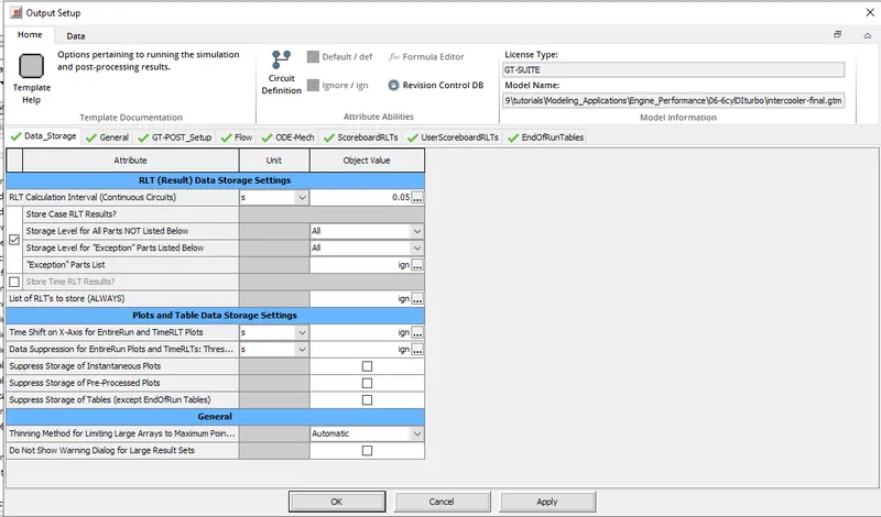
Data Storage:
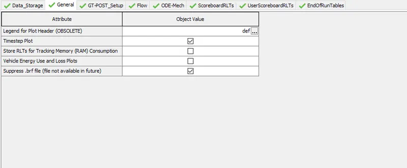
GENERAL:
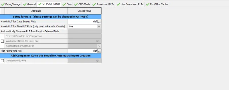
GT-Post setup:
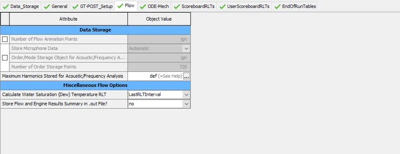
Flow:
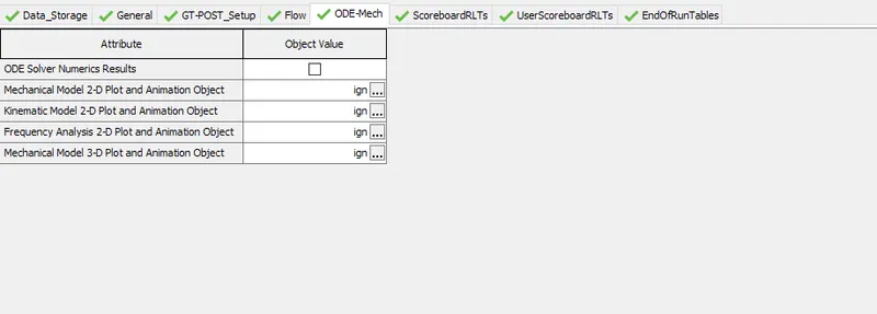
ODE Mech:
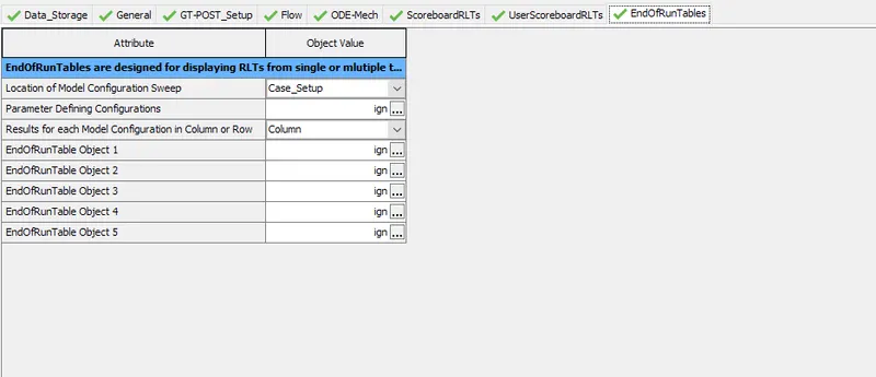
End of Run Tables:
4. Problem: (50 Marks)
Given
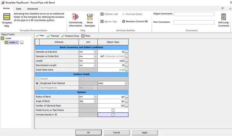
- Diameter of cooler inlet and outlet pipe= 50 mm
- Length of the CAC= 1000 mm
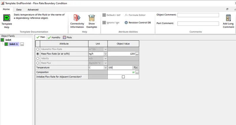
- Inlet mass flow rate = 1200 kg/ h at 100 degC
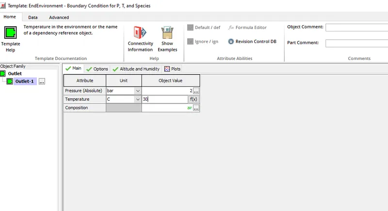
- Outlet pressure 2 bar at 30 deg C
- Calculate the Average heat transfer at Charge air cooler (CAC)
- Calculate pressure drop across CAC
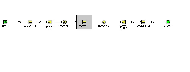
Opwn the intercooler settings and make changes as required.
CHnging the inlet mass flow rate and temperature
Changing the outlet conditions
Chnage the simulation time to 1 sec in run setup. And submit the case for solving.
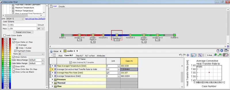
Average heat transfer rate = 7.5539484 KW
Average Pressure drop = 1.1233449E-5 bar