Week 1: Channel flow simulation using CONVERGE CFD
AIM :- Run a Simulation to analyze air flow through the Chenal and find out velocity contour, pressure contour and mass flow rate through the different mass size.

Flow through a channel:
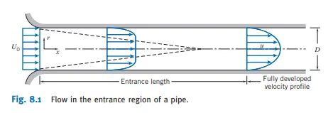
When a fluid enter into the pipe there is a Entrance length and Fully developed flow .The entrance length create is due to the free flow fluid and boundary layer created due to the viscosity of the fluid. when the boundary layer are meet together then the fully developed flow was created.
Re (Reynold no)=rho*v*d/mi
If Re<= 2300 the flow is laminar flow.
Create 2D profile for Channel flow:
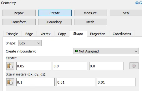
Syntax to create the dox:
Geometry>>create>>shape>>box
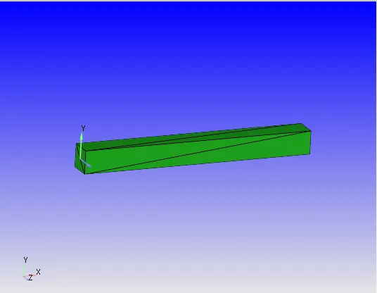
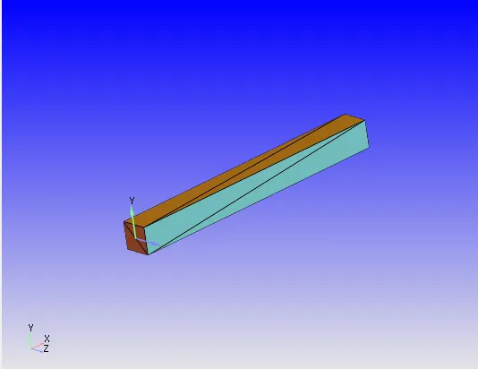
Now create the boundary:
Syntax for the boundary:
Geometry>>Boundary>>Flag
add new boundary.
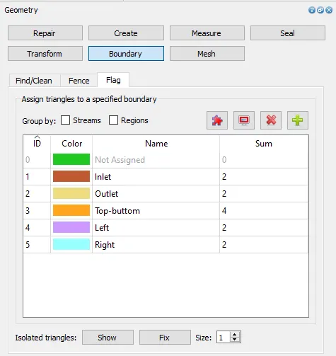
Setup the normal:
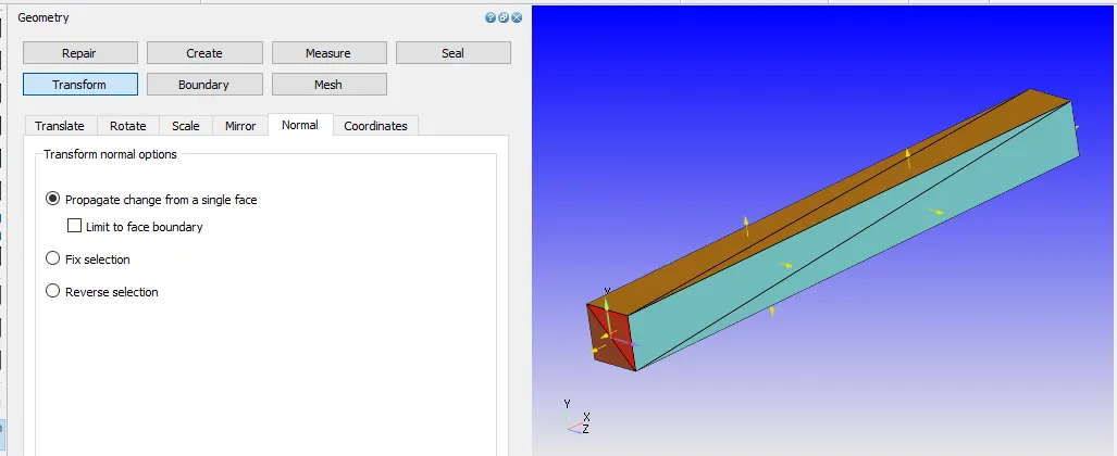
Normal shows the aria vector of the face. To set the direction of the flow the aria vector should be the direction of the flow. so the aria vector should in the direction of the flow.
Syntax:
Transfer>>Normal>>(select the any face, whose normal vector was nor correct)>>apply
Run the Diagnosis :
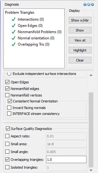
By the Diagnosis it was able to find the the intersection error, open edge angle and overlapping tries.
From this We conform the geometry is perfect.
Case setup:
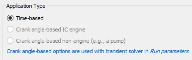
Application type:
This is Time based simulation. It is steady flow process but the simulation will take place in cyclic manner.
Materials:
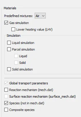
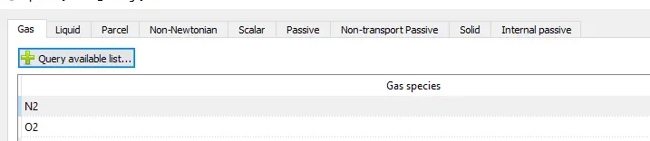
Air is the working fluid and we are doing only gas simulation and to define the elements in the air we have to enable the specie.
Simulation parameter:
Run parameter:
Solver :steady state solver
Simulation mode : Full Hydrodynamic
Gas flow solver is Compressible
Steady state monitor:
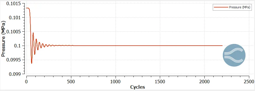
In this monitor the variable to get converge solution with less no of cyclic simulation.
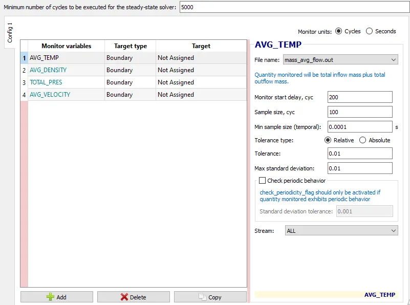
It execute minimum 5000 no of solution. and it monitor after 200 cycle collect sample 100.
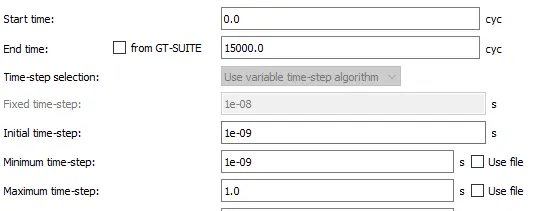
Simulation time parameter:
Solver parameter:
Here we use PISO scheme and pressure based solver.

Boundary Condition:
Inlet set the boundary as inflow and set the pressure 100001KPa and define the region.
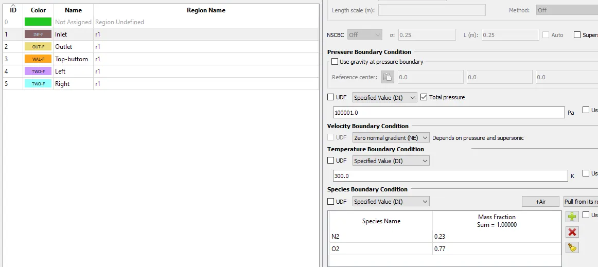
Outlet is out flow type and the pressure was 100000Kpa.
Top-bottom was wall type and the wall was no slip type .
Left and right are 2D boundary.
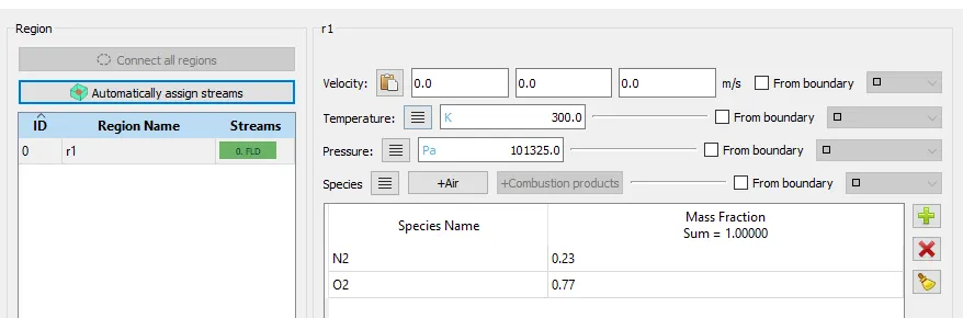
Physical modelers:
Turbulence model:
Uncheck the Turbulence model.
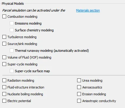
Base grid:
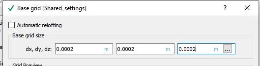
It is laminar flow so uncheck the turbulent variables.
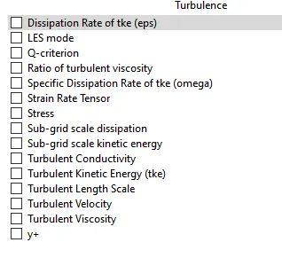
Now the setup is completed and import the set up files .
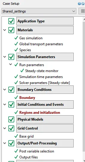
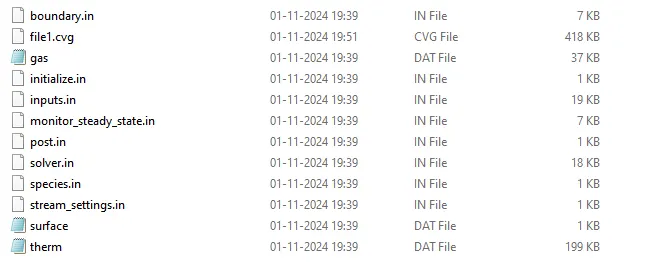
Run the setup:
To run the set up we have to take to the file where the in put files are there. then run the following executive (mpiexec) and executable(converge)

After complete the running
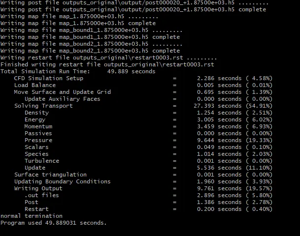
Output:
Convert the file into the paraview format.
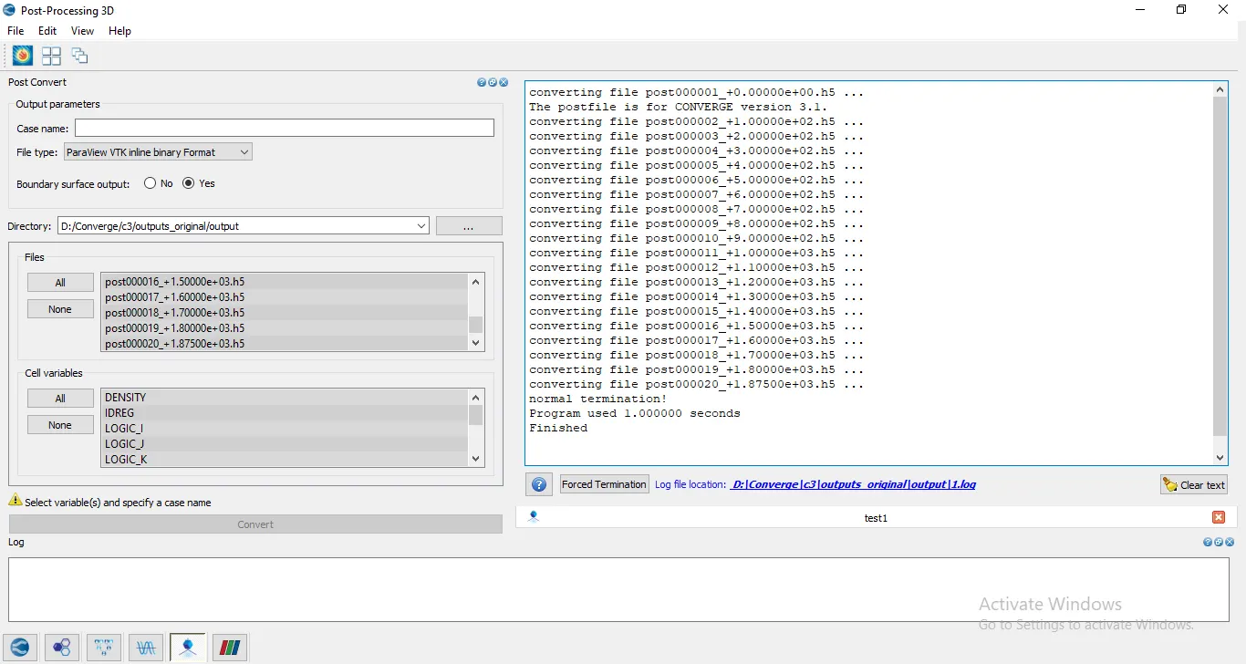
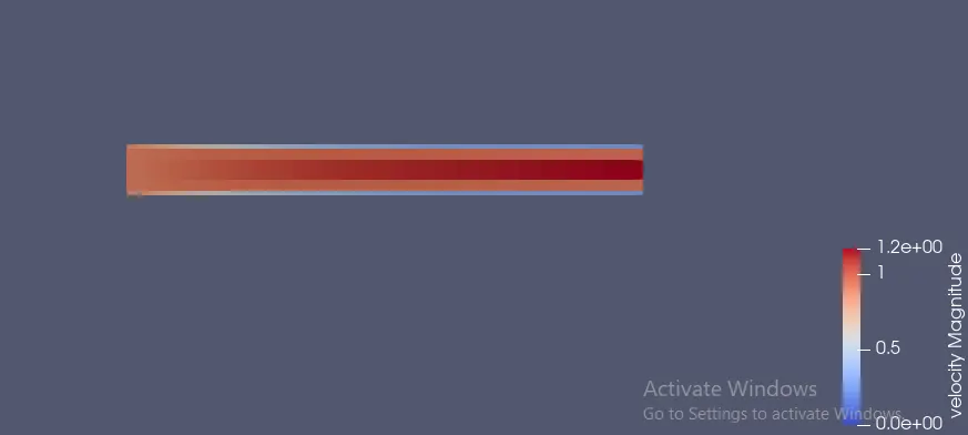
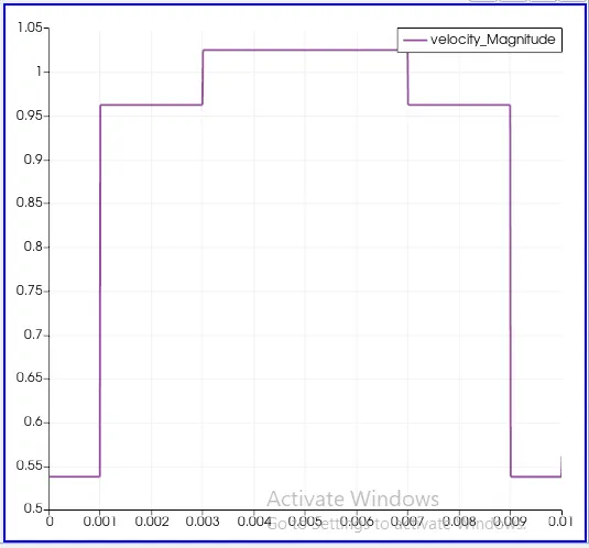
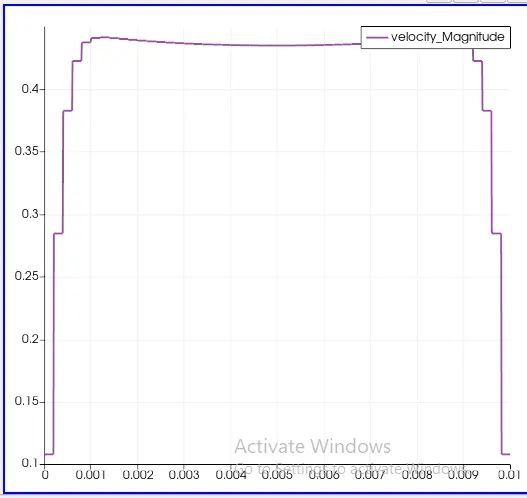
Output for case 1:
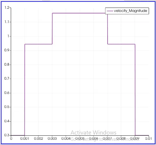
Velocity:
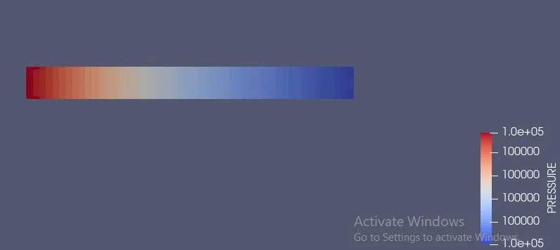
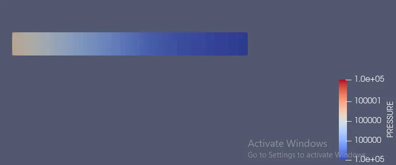
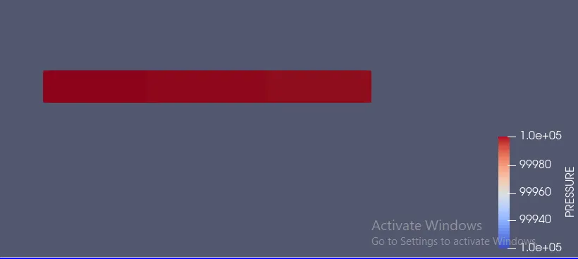
pressure:
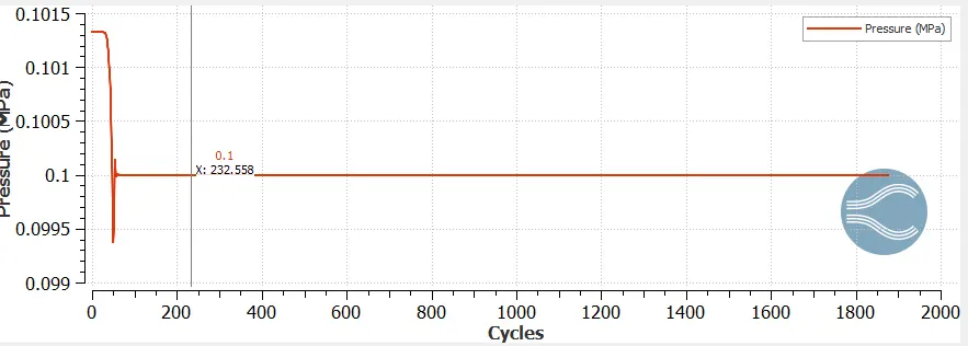
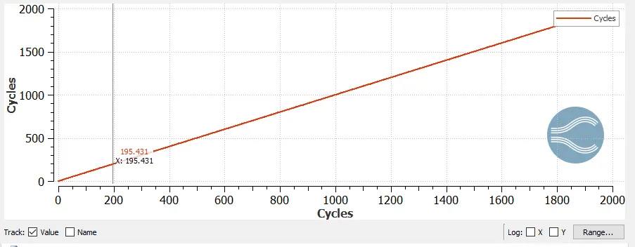
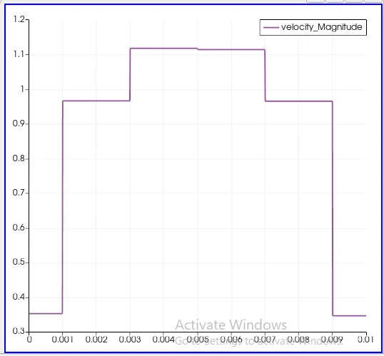
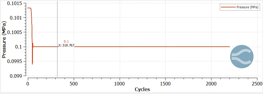
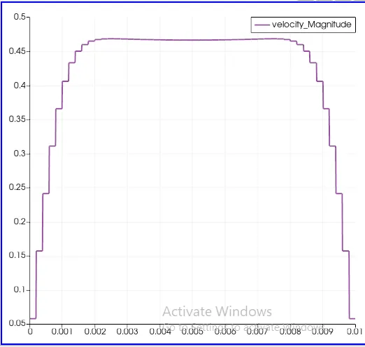
Case 2 Output:
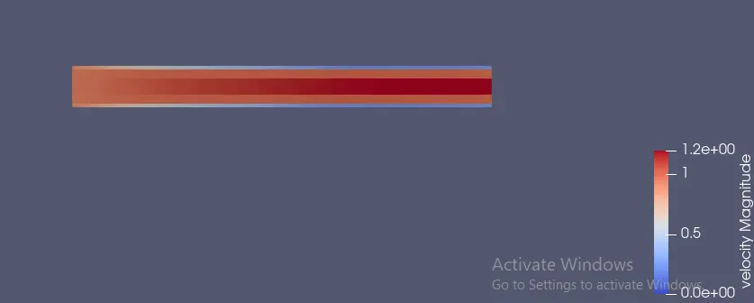
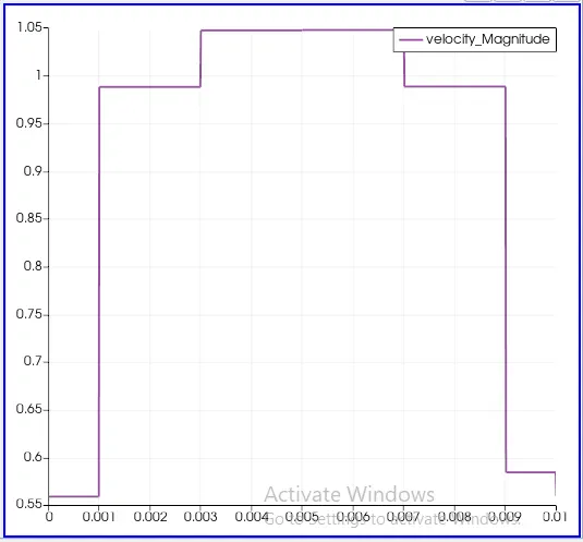
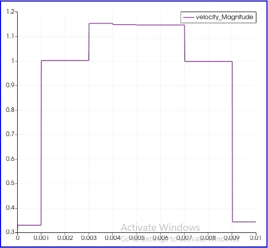
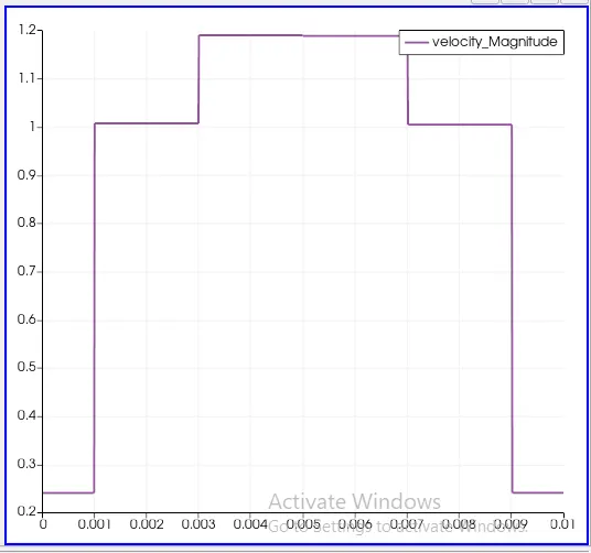
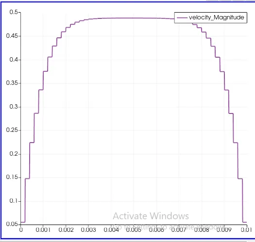
Case 3 Output:
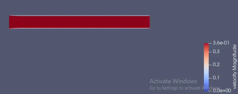
pressure
1. Increase the Cell quantity it will increase the Clarity of the Plot.