Channel flow simulation using CONVERGE CFD
Introduction
Converge CFD is a relatievely new computational software that offers a smooth and efficient graphical user interface to set up different cases of study. In this simple project, a simple flow through a channel will be set up using Converge, and the results will be post processed using both converge and PARAVIEW. This helps familiarize with the converge and PARAVIEW interfaces.
Aim
To simulate steady flow through to a channel
To view results for different grid sizes
To post process and visualize the flow
Procedure
A simple geometry represnting a channel is created 0.1, 0.01 and 0.01 in X,Y,Z directions respectively.
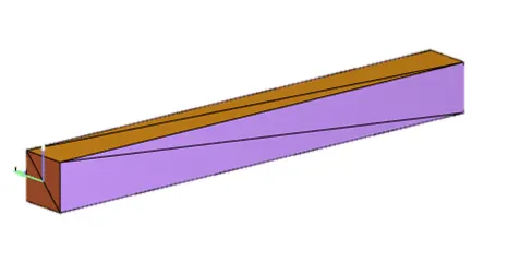
Fig. 1. Channel geometry
The setup parameters are not changed much, siince this is an initial and simple study.
Inlet and outlet are inflow and outflow, with pressure 10001 Pa and 100000 Pa respectively.
In basic explaination, the PISO solver was used, which is an improvement made to acknowledge the downfall of the SIMPLE solver in terms of accuracy and stability. It also generally requires less CPU time.
Flow was considered to be steady, and laminar, hence the turbulence model was turned off.
3 different base mesh sizes are used,
- dx = 2e-4m, dy = 2e-4m, dz = 2e-4m
- dx = 1.5e-4m, dy = 1.5e-4m, dz = 1.5e-4m
- dx = 1.2e-4m, dy = 1.2e-4m, dz = 1.2e-4m
The entire simulation is executed using CYGWIN terminal.
Simulation was run for 15,000 cycles initally.
Case 1: dx = 2e-4m, dy = 2e-4m, dz = 2e-4m
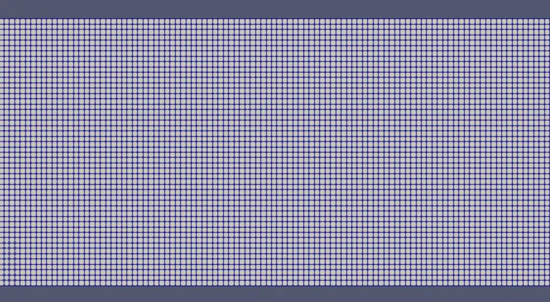
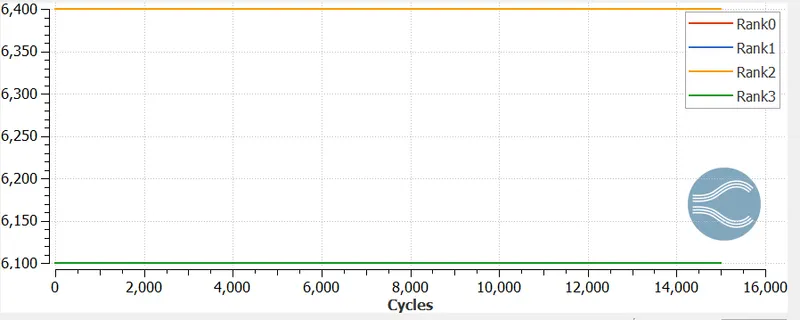
Fig. 2: Cell count, that is the cells used by each processor to run the simulation.
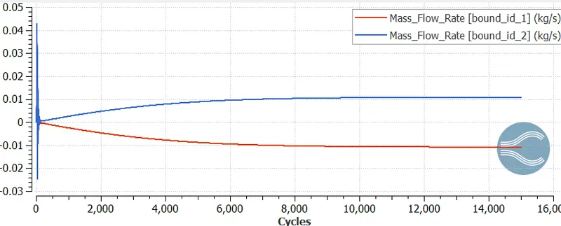
Fig. 3: Mass flow rate, which appears to converge smoothly and early.
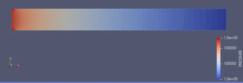
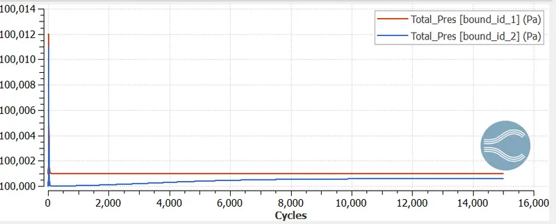
Fig. 4: Pressure profile and convergence.
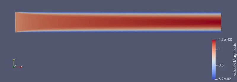
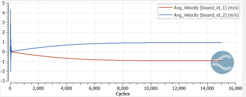
Fig. 5: Velocity profile and convergence.
Case 2: dx = 1.5e-4m, dy =1.5e-4m, dz = 1.5e-4m
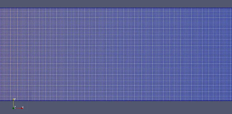
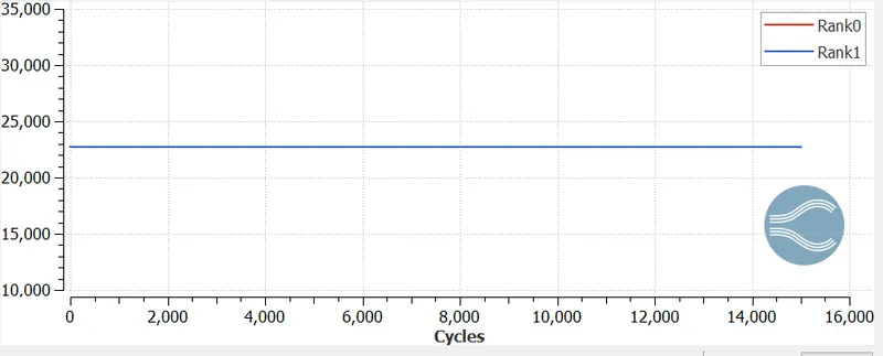
Fig. 6: Cell count, that is the cells used by each processor to run the simulation (Note: only 2 processors were used for this case).
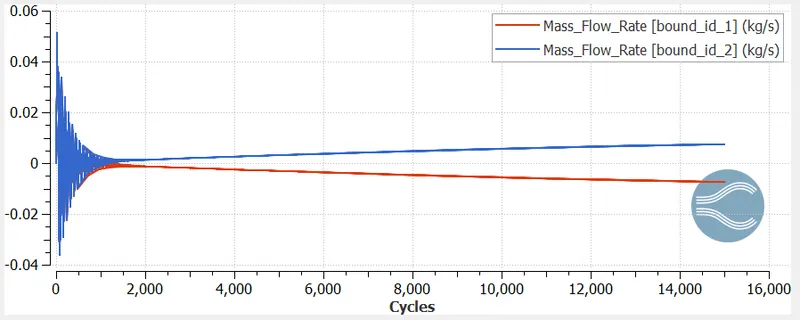
Fig. 7: Mass flow rate, which appears not to converge at 15,000 cycles.
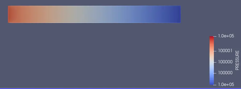
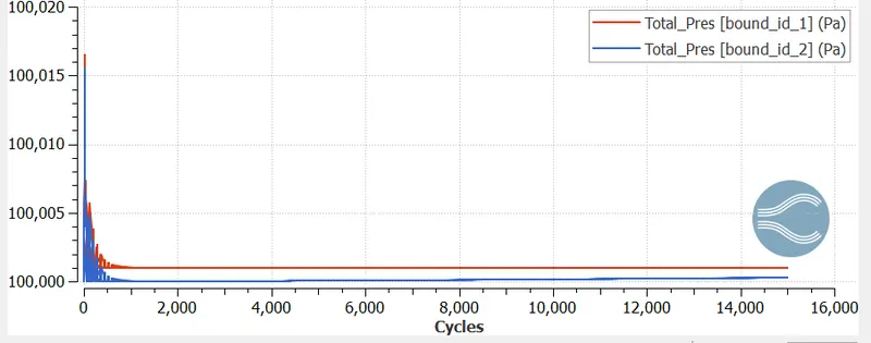
Fig. 8: Pressure profile and convergence.
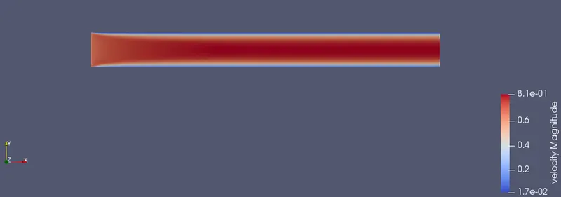
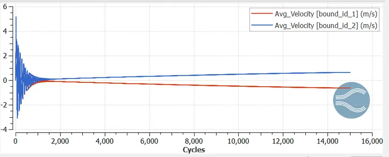
Fig. 9: Velocity profile and which clearly appears to not have converged.
Now, we know that this solution is innacurate for the current mesh size. Since our aim is to run an even finer mesh size, the results above will be neglected. However, we now know that 15,000 cycles is clearly not enough. Hence, for the next case, number of cycles is increased to 35,000.
Another modification made is that during initialization, pressure is set to 100000 Pa instead of 101325 Pa. Since this is close to our initial conditions, convergence should be expected to be faster.
Case 3: dx = 1.2e-4m, dy =1.2e-4m, dz = 1.2e-4m

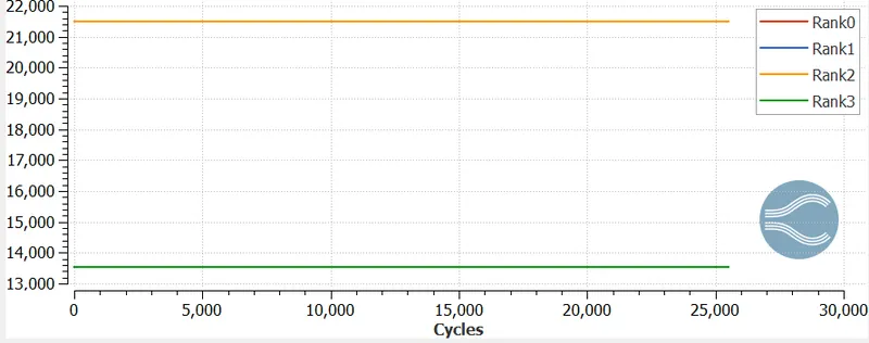
Fig. 10: Cell count, that is the cells used by each processor to run the simulation.
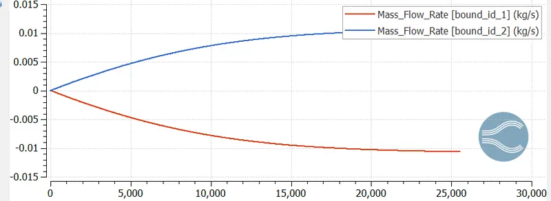
Fig. 11: Mass flow rate, which appears to converge smoothly.
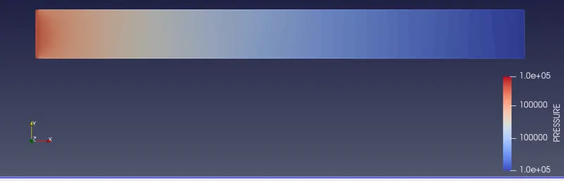
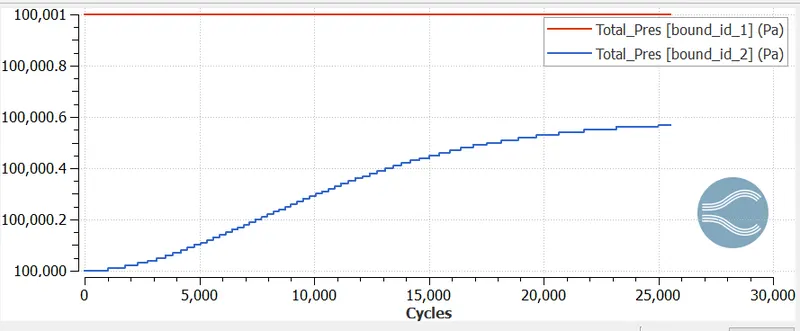
Fig. 12: Pressure profile and convergence.
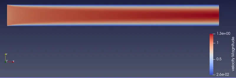
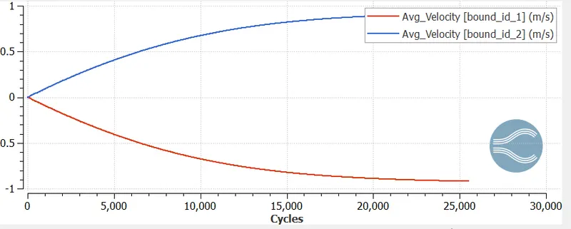
Fig. 13: Velocity profile and convergence.
Conclusion:
In this study, simple channnel flow was simulated.
- Main take away is that an increase in cell count, or mesh size leads to a much longer time period of convergence.
- Case 1 converged well within 15,000 cycles.
- Case 2 demonstrated that more number of cycles are required for convergence.
- Case 3 showed that there is a major increase cycle duration for convergence.