Week 1 Challenge
1. AIM :
To create a new project and name it appropriately using revit.
TOOLS USED:
- MENU
- TEMPLATE
- OPEN
PROCEDURE:
step 1:
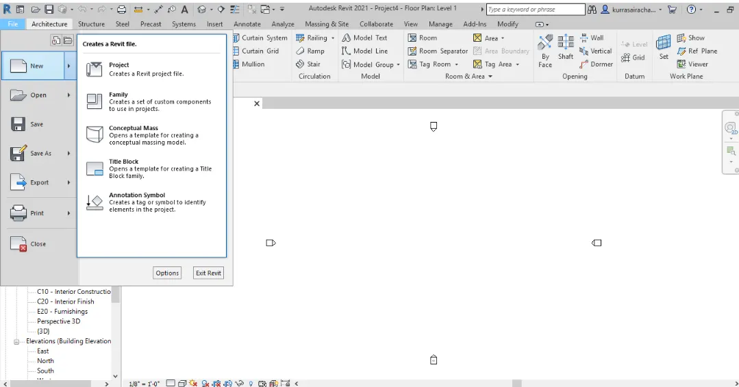
click on the file menu
click on new and select project.
we get a tab having template selection
.
step 2:
we get a tab having template selection
select architectural template and name it as required.
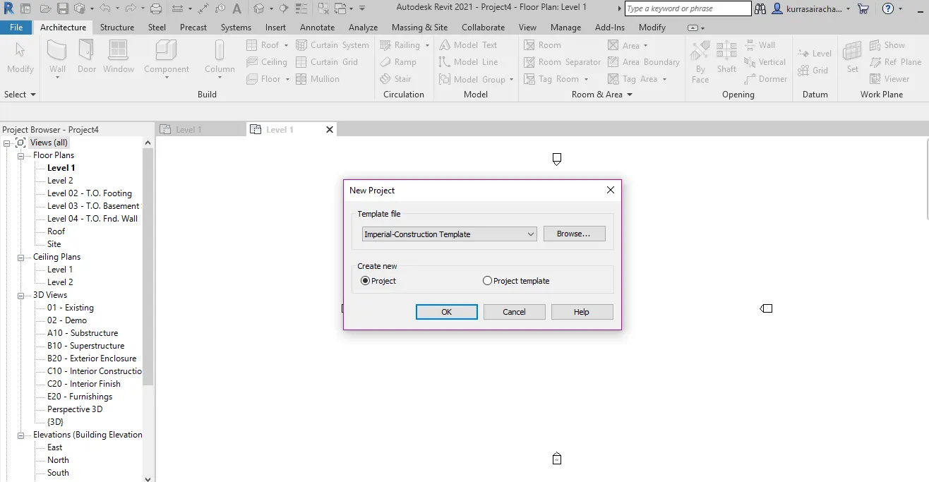
RESULT:
file will be created and name it accordingly by using above steps.
2)
AIM: to save a new project file and close and open the file using icons from toolbar.
tools used:
- FILE
- SAVE AS
PROCEDURE:
- click on the file tab
- click on save as and then project
- save as a file
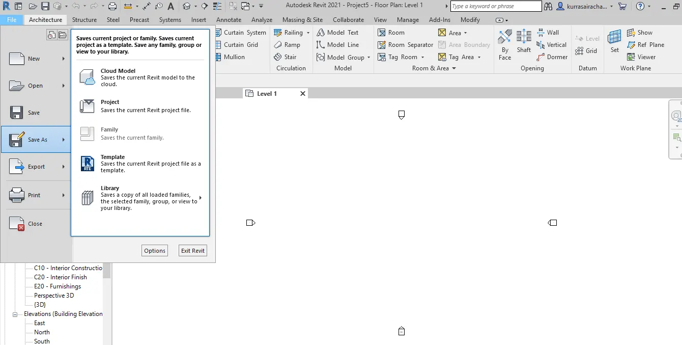
- name the project to save it
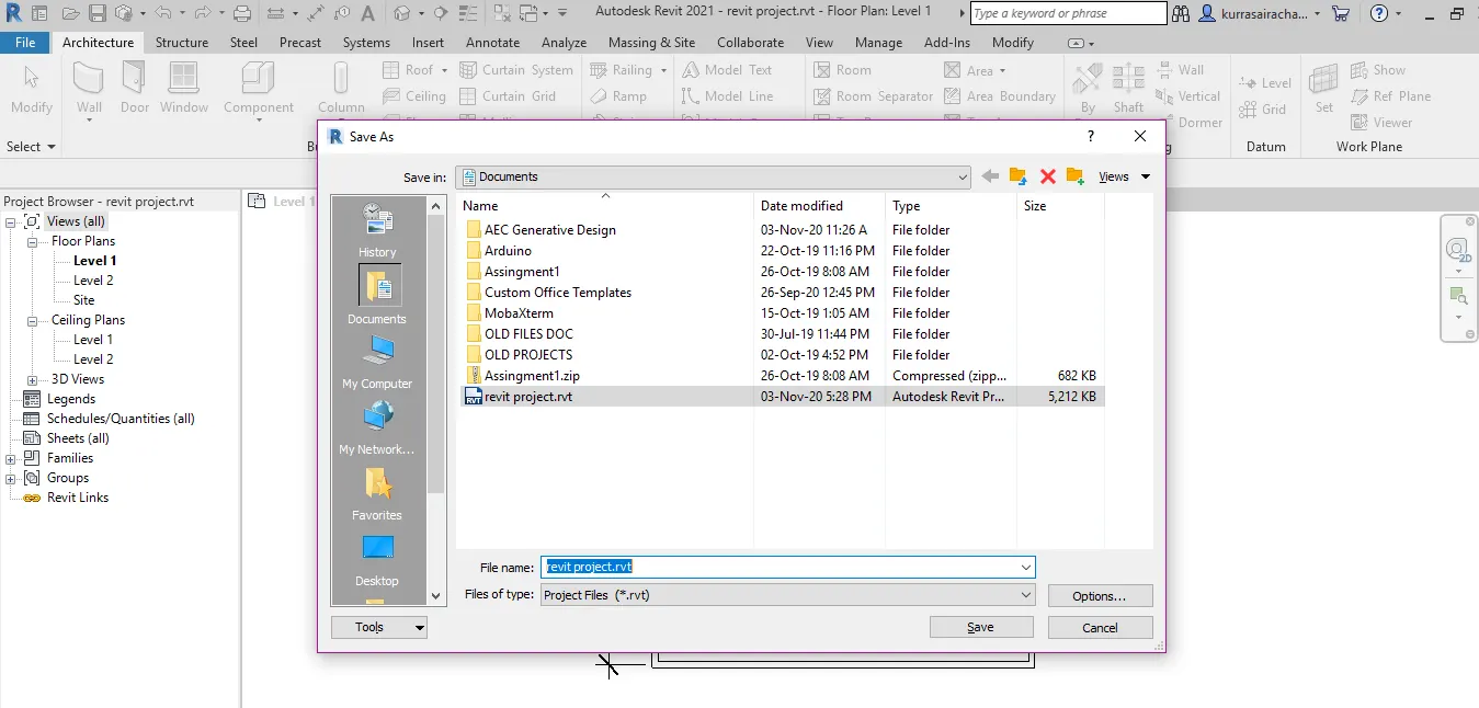
4)using the close tool bar close the file and we will be redirected to homepage.
5)by using open toolbar we can open the file which has been created early.
RESULT:
the file has been saved according by follwing procedure using toolbars.
3)
AIM: to create a rectangular layout using architectural tool.
TOOLS USED:
- ARCHITECTURAL
- WALL
- TEMPLATE
- PLACEWALL(RECTANGLE)
PROCEDURE:
1.open the revit software
2.switch to architectural tab
3.select wall to create non structural wall
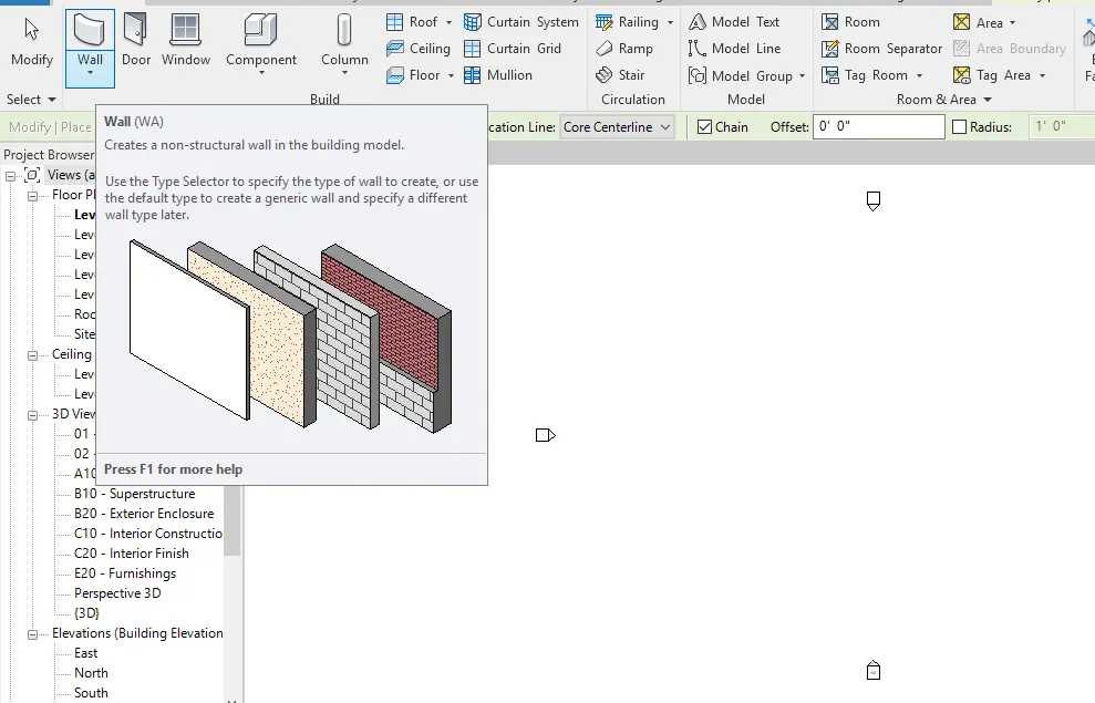
4.click the architectural wall to place wall in the model space
5.click on rectangle or linear to draw a frame work of wall about 40'0" * 35'0"
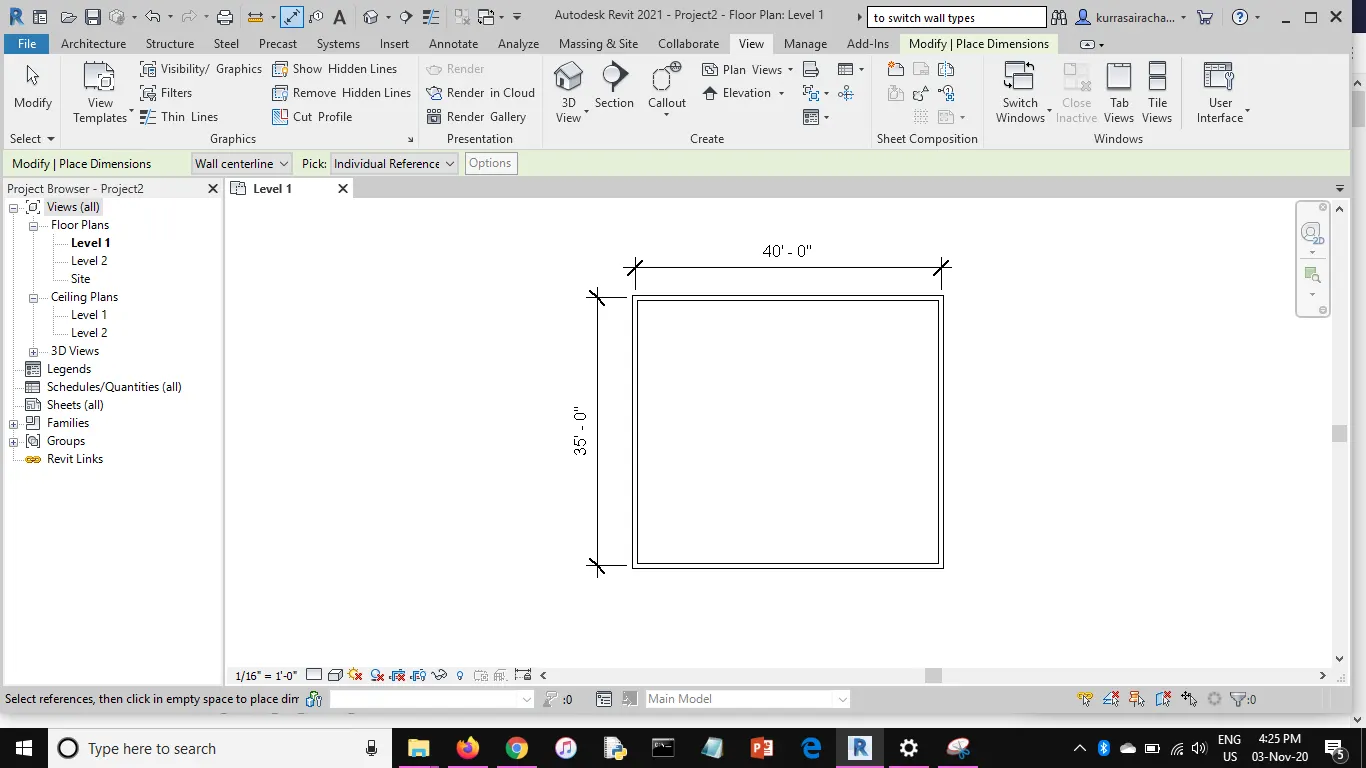
RESULT:
the rectangular layout is created by using architectural toolbar in revit software.
4)
AIM:To add dimesnsions to the layout by using alligned options from annote toolbar.
TOOLS USED:
1.ANNOTE
2.ALLIGNED
PROCEDURE:
1.select the tab created priviously (level1)
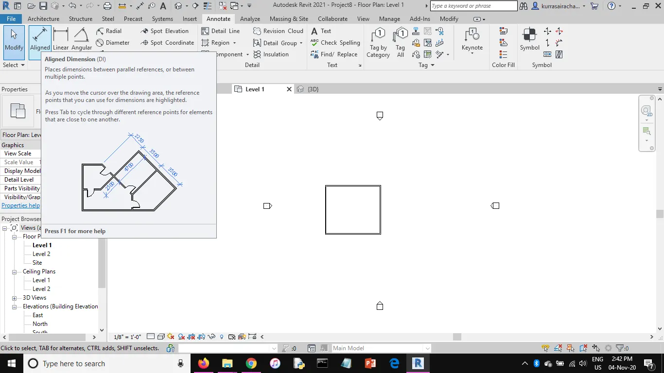
2.click on the annote tool bar and click on alligned option
3.select from one end of the wall to another end
4.click on enter to get the dimensions.
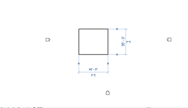
RESULT: The dimensions are added to the frame work by using alligned options.
5)
AIM:To switch to different types of walls using properties browser.
TOOLS USED:
1.FILE
2.PROPERTIES
3.WALL TYPES
PROCEDURE:
1.select the wall in architectural tab
2.click on the properties.
3.select the drop down icon
4.we can find the different types of walls.
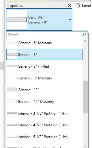
RESULT:
different types of walls can be switched by using properties browser.
6)
AIM:TO create a 3D view from the view toolbar and save it with appropriate name.
TOOL BAR:
1.VIEW
2.3D
3.SAVE
PROCEDURE:
1.open the file that has been created early.
2.select the view tool bar
3.click on 3D view
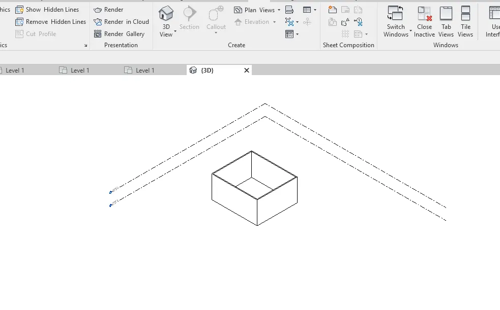
4.right click save it with approprite name
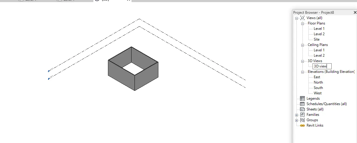
.
RESULT:
the layout has been crated in 3D view using view tool bars
7)
AIM: to navigate through the 3D model using view cube.
TOOLS USED:
1) VIEW TOOL BAR
2)3D VIEW
3)VIEW CUBE
PROCEDURE:
- Open the view tool and click on 3D view
- click on the view cube then we can find a navigation wheel.
- with the help of orbit tool we can see the cube in 360 view
- select the pan to move in direction
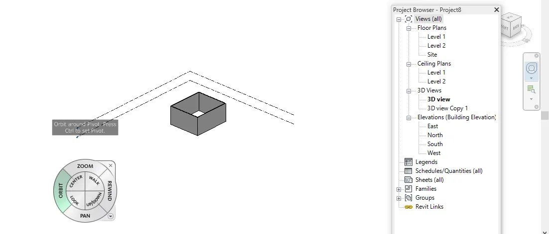
RESULT:
navigtion is done through the 3D model using view cube.
8)
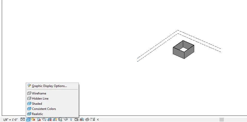
AIM:TO use visibility settings option below to switch model to shaded ,realistic, hidden line options.
TOOLS USED:
- 3D VIEW
- VISIBILITY
- OPTIONS.
PROCEDURE:
1.open the 3D view using view tool bar.
2.At bottom we can see a cube option contains display option.
3.click on it we get shaded,realistic,hidden line options.
9)
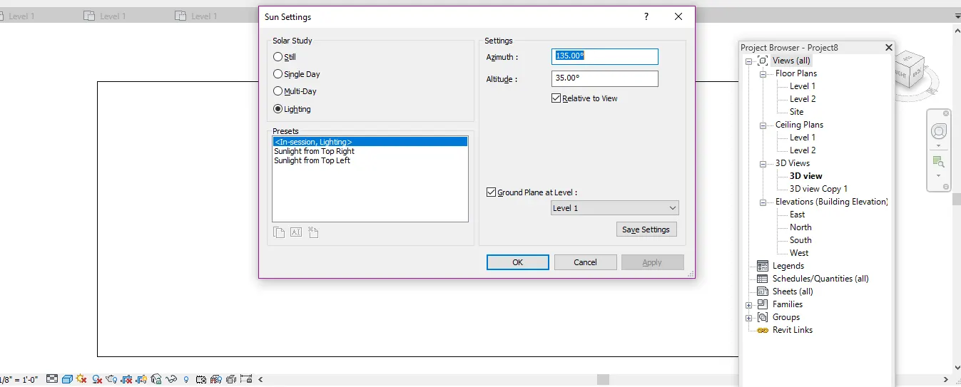
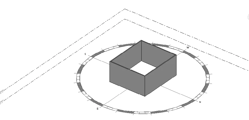
AIM:to turn on the light on and off to view shadings in the layout created.
TOOLS USED:
- file
- manage
- additional settings
PROCEDURE:
1.click on the manage tool bar
2.selection additional settings
3.click on the solar study ,sun stettings and click ok
4.select the sunpath at the bottom and make it on and off to get the shadings.
RESULT:
10)
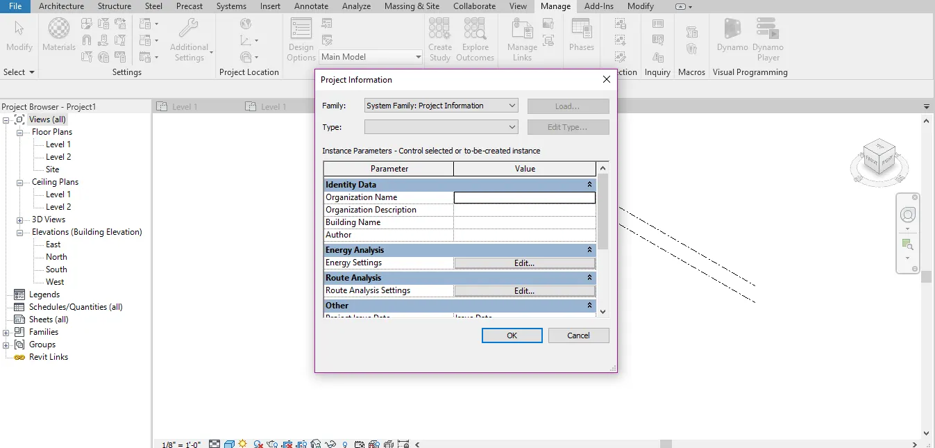
AIM:to use the manage toolbar to enter project settings ,project name,and project isuue date .
TOOLS USED:
- manage tool
- project information
PROCEDURE:
- select the manage toolbar
- click on project information
- we select select the name and date and fill it accordingly.
11)what is analyze toolbar used in revit?how it is benificial for design and modelling.
ans: Analyse tool bar is the tool which helps to combine the differemt tools in the structure,load combination,boundary conditions etc., it is used to analyse the structure with all the different loads applied in the object which gives the analysis report as the resuly.it helps to detect the load failure in the structure.
12)what are the links that revit supports to be linked to the model?
ans: links that revit supports are:
- link revit
- link IFC
- link topography
- link CAD
13)Why do you need collabarate tab in revit?how it supports modelling and its efficency?
ans: Collabarate in revit is a cloud based service which allows any revit users inside or out seide to collabarate the revit model. many users can work under the same planning or drawing ,which makes more productive and efficient and time can also reduced in completeing project.