Week 1 Challenge
(1)
- Write the steps involved in uploading a .std file through webmail.
Steps:
> First open STAAD PRO. software
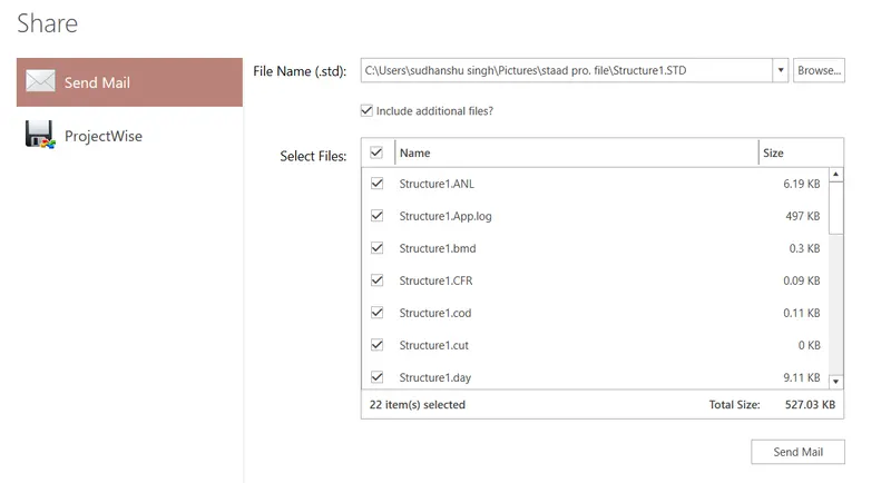
>then, select the share option
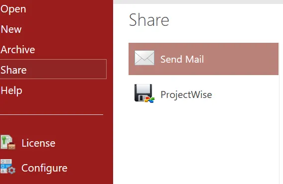
> now select the file you want to send through mail, and click on send.
- Name the different materials that can be designed using STAAD Pro.
> concrete
> steel
> Aluminum
> Timber
- Is it possible to capture images in STAAD Pro?
Yes, it is.
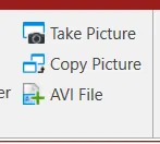
>Go to the utility menu
> now click on the take picture option.
- Name the three ways by which you can create a model.
> Analytical modeling
> Physical modeling
> Building planner
- Write the steps followed to assign properties in a model.
Steps:-
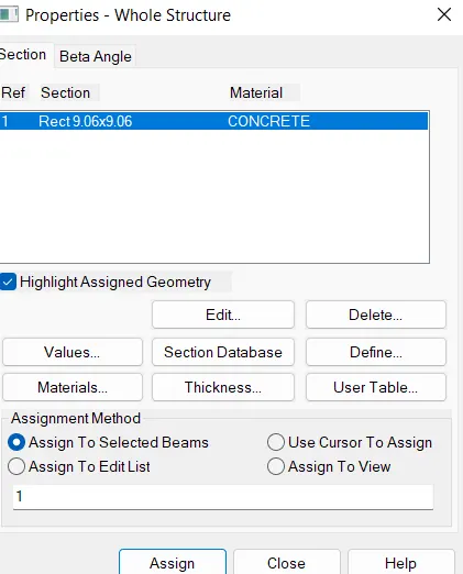
> First define the property of the section.
> Then select the property and assign it to the section.
(2)
- Name any six design parameters involved in RCC design
>> clear cover of member
>> Depth of member
>> Fc ( compressive strength )
>> Fy main reinforcement
>> Maximum bar diameter
>> ULy and ULz ( unsupported length factor )
- What are the different cursor types available in STAAD Pro?
>> Node Cursor
>> Beam cursor
>> Plate cursor
>> surface cursor
>> solid cursor
>> geometry cursor
>> member cursor
- How will you generate different views for a model
Steps:
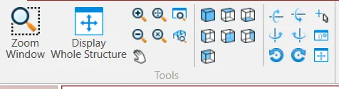
>> Go to view options
>> and select the different view options.
- Explain the procedure to define a “Simply Supported” condition in STAAD Pro
Steps:
>> First create a beam and assign the property and material
>> go to support and first create support ( fixed, pinned, roller)
>> now select the support and assign it to the beam on both ends.

- Name any five topics that you will include while creating DBR.
>> Introduction of projects.
>> structural layout
>> Loads and combination
>> Analysis and design method
>> appendix
- Describe the term “Multi-material design” of STAAD Pro.
>> Multi-material design means we can design the structure using more than two materials in STAAD PRO. For example, we can design a building made of concrete and steel frames simultaneously.
(3)
- Name the structure systems in STAAD Pro.
| Name of structure system | Geometry | Loading | Deformation | Joints |
| Space | 3D | 3D | 3D | ANY |
| Plane | 2D | 2D | 2D | ANY |
| Frame | 2D | Perpendicular to the XZ plane | Perpendicular to the XZ plane | ANY |
| Truss | 3D | 3D | 3D | PINNED |
- Explain the coordinate system adopted in STAAD Pro software.
| Types of the coordinate system | Structure |
|
same for the whole structure |
|
assign for a particular member( But x- axis is same as global) |
- Elaborate on DBR and its uses
>> DBR means Design Basis Report. It is documented information about the project. There are different types of DBR such as structural DBR, architectural DBR, HBC DBR, etc. In this DBR, we make a report on the structural layout. load combination and design and analysis procedure.
Uses of DBR:
>> Help in understanding project location, client name, and general specification of projects.
>> Help to avoid scope creep.
>>Help the engineer who is assigned in mid of the project.
- Explain the different types of analysis options in STAAD pro.
>> Perform analysis: It is a first-order linear analysis.
: Deformation is elastic.
: Deformation is calculated only for primary load cases.
>> P-delta analysis: It is 2nd-order non linear analysis.
: deformation is calculated when the primary load and secondary load act simultaneously
: It is done in generally seismic load cases.
: It is generally used for high-rise buildings.
- Explain the difference between Fixed and Fixed But conditions.
| FIXED | FIXED BUT CONDITIONS |
|
|
AIM: Create a STAAD Model
Specification:
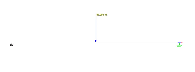
a. A beam of span 16m
b. Support: Fixed on one end and Roller support(Horizontal) on the other end
c. A point load of 50 kN at the mid-point
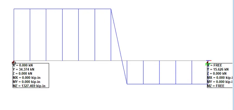
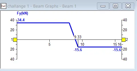
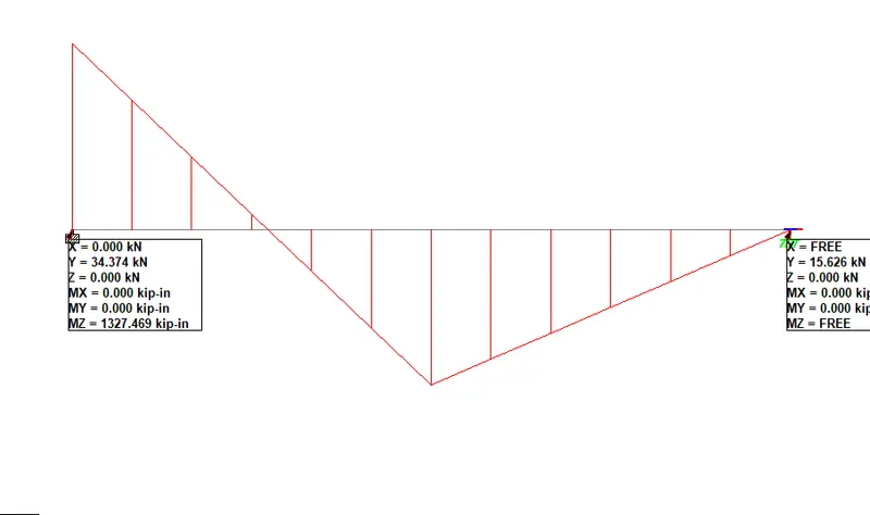
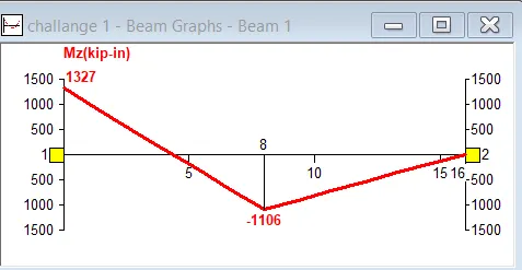
d. Draw SFD and BMD using software
Procedure:
- First, create a file in STAAD PRO.
- Now create two nodes with a distance of 16 m between them.
- Add beam
- now define a property of the beam.
- Now create two support- fixed and roller
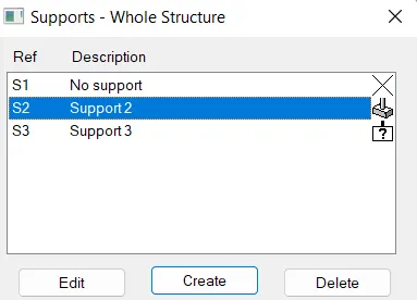
- Now assign the fixed support at one end and roller support at another end of the beam.

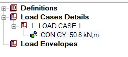
- Now define the case and put the value 50 KN and assign it to the beam at the midpoint.
RESULT:
- SFD of Beam
- BMD of beam
THANK YOU.